EP2208929A2 - Procédé de combustion pour un four à régénération - Google Patents
Procédé de combustion pour un four à régénération Download PDFInfo
- Publication number
- EP2208929A2 EP2208929A2 EP09015900A EP09015900A EP2208929A2 EP 2208929 A2 EP2208929 A2 EP 2208929A2 EP 09015900 A EP09015900 A EP 09015900A EP 09015900 A EP09015900 A EP 09015900A EP 2208929 A2 EP2208929 A2 EP 2208929A2
- Authority
- EP
- European Patent Office
- Prior art keywords
- exhaust gas
- combustion
- regenerative
- combustion exhaust
- regenerator
- Prior art date
- Legal status (The legal status is an assumption and is not a legal conclusion. Google has not performed a legal analysis and makes no representation as to the accuracy of the status listed.)
- Granted
Links
Images



Classifications
-
- F—MECHANICAL ENGINEERING; LIGHTING; HEATING; WEAPONS; BLASTING
- F23—COMBUSTION APPARATUS; COMBUSTION PROCESSES
- F23L—SUPPLYING AIR OR NON-COMBUSTIBLE LIQUIDS OR GASES TO COMBUSTION APPARATUS IN GENERAL ; VALVES OR DAMPERS SPECIALLY ADAPTED FOR CONTROLLING AIR SUPPLY OR DRAUGHT IN COMBUSTION APPARATUS; INDUCING DRAUGHT IN COMBUSTION APPARATUS; TOPS FOR CHIMNEYS OR VENTILATING SHAFTS; TERMINALS FOR FLUES
- F23L15/00—Heating of air supplied for combustion
- F23L15/02—Arrangements of regenerators
-
- F—MECHANICAL ENGINEERING; LIGHTING; HEATING; WEAPONS; BLASTING
- F23—COMBUSTION APPARATUS; COMBUSTION PROCESSES
- F23D—BURNERS
- F23D14/00—Burners for combustion of a gas, e.g. of a gas stored under pressure as a liquid
- F23D14/20—Non-premix gas burners, i.e. in which gaseous fuel is mixed with combustion air on arrival at the combustion zone
-
- C—CHEMISTRY; METALLURGY
- C03—GLASS; MINERAL OR SLAG WOOL
- C03B—MANUFACTURE, SHAPING, OR SUPPLEMENTARY PROCESSES
- C03B5/00—Melting in furnaces; Furnaces so far as specially adapted for glass manufacture
- C03B5/16—Special features of the melting process; Auxiliary means specially adapted for glass-melting furnaces
- C03B5/235—Heating the glass
-
- C—CHEMISTRY; METALLURGY
- C03—GLASS; MINERAL OR SLAG WOOL
- C03B—MANUFACTURE, SHAPING, OR SUPPLEMENTARY PROCESSES
- C03B5/00—Melting in furnaces; Furnaces so far as specially adapted for glass manufacture
- C03B5/16—Special features of the melting process; Auxiliary means specially adapted for glass-melting furnaces
- C03B5/235—Heating the glass
- C03B5/237—Regenerators or recuperators specially adapted for glass-melting furnaces
-
- F—MECHANICAL ENGINEERING; LIGHTING; HEATING; WEAPONS; BLASTING
- F23—COMBUSTION APPARATUS; COMBUSTION PROCESSES
- F23D—BURNERS
- F23D14/00—Burners for combustion of a gas, e.g. of a gas stored under pressure as a liquid
- F23D14/46—Details
- F23D14/66—Preheating the combustion air or gas
-
- F—MECHANICAL ENGINEERING; LIGHTING; HEATING; WEAPONS; BLASTING
- F23—COMBUSTION APPARATUS; COMBUSTION PROCESSES
- F23L—SUPPLYING AIR OR NON-COMBUSTIBLE LIQUIDS OR GASES TO COMBUSTION APPARATUS IN GENERAL ; VALVES OR DAMPERS SPECIALLY ADAPTED FOR CONTROLLING AIR SUPPLY OR DRAUGHT IN COMBUSTION APPARATUS; INDUCING DRAUGHT IN COMBUSTION APPARATUS; TOPS FOR CHIMNEYS OR VENTILATING SHAFTS; TERMINALS FOR FLUES
- F23L2900/00—Special arrangements for supplying or treating air or oxidant for combustion; Injecting inert gas, water or steam into the combustion chamber
- F23L2900/15022—Special arrangements for supplying or treating air or oxidant for combustion; Injecting inert gas, water or steam into the combustion chamber using pre-purging regenerator beds
-
- Y—GENERAL TAGGING OF NEW TECHNOLOGICAL DEVELOPMENTS; GENERAL TAGGING OF CROSS-SECTIONAL TECHNOLOGIES SPANNING OVER SEVERAL SECTIONS OF THE IPC; TECHNICAL SUBJECTS COVERED BY FORMER USPC CROSS-REFERENCE ART COLLECTIONS [XRACs] AND DIGESTS
- Y02—TECHNOLOGIES OR APPLICATIONS FOR MITIGATION OR ADAPTATION AGAINST CLIMATE CHANGE
- Y02E—REDUCTION OF GREENHOUSE GAS [GHG] EMISSIONS, RELATED TO ENERGY GENERATION, TRANSMISSION OR DISTRIBUTION
- Y02E20/00—Combustion technologies with mitigation potential
- Y02E20/34—Indirect CO2mitigation, i.e. by acting on non CO2directly related matters of the process, e.g. pre-heating or heat recovery
-
- Y—GENERAL TAGGING OF NEW TECHNOLOGICAL DEVELOPMENTS; GENERAL TAGGING OF CROSS-SECTIONAL TECHNOLOGIES SPANNING OVER SEVERAL SECTIONS OF THE IPC; TECHNICAL SUBJECTS COVERED BY FORMER USPC CROSS-REFERENCE ART COLLECTIONS [XRACs] AND DIGESTS
- Y02—TECHNOLOGIES OR APPLICATIONS FOR MITIGATION OR ADAPTATION AGAINST CLIMATE CHANGE
- Y02P—CLIMATE CHANGE MITIGATION TECHNOLOGIES IN THE PRODUCTION OR PROCESSING OF GOODS
- Y02P40/00—Technologies relating to the processing of minerals
- Y02P40/50—Glass production, e.g. reusing waste heat during processing or shaping
Definitions
- the present invention relates to a combustion control method for regenerative-combustion heating furnace in which a heating furnace is provided with at least a pair of regenerative burners each including a burner portion equipped with a fuel injection nozzle and a regenerator accommodating a heat storage material therein and in which the paired regenerative burners are switched to alternate between operations in a manner such that one regenerative burner of the pair performs a combusting operation by introducing a combustion air to the burner portion via the regenerator and injecting a fuel gas from the fuel injection nozzle of this burner portion while the other regenerative burner performs an operation of introducing a combustion exhaust gas into the regenerator and allowing the heat storage material to store heat from the combustion exhaust gas before discharging the combustion exhaust gas.
- the invention is characterized by preventing the following problem encountered by the above regenerative-combustion heating furnace.
- the regenerative burner which is performing, at the time of operation stop, the operation of introducing the combustion exhaust gas into the regenerator and allowing the heat storage material to store the heat from the combustion exhaust gas before discharging the combustion exhaust gas may suffer corrosion at the regenerator or an exhaust gas discharge pipe and the like for discharging the combustion exhaust gas.
- the regenerative-combustion heating furnace has heretofore been used for heat treating the subject material.
- the regenerative-combustion heating furnace is provided with at least a pair of regenerative burners each including the burner portion equipped with the fuel injection nozzle and the regenerator accommodating the heat storage material therein.
- the pair of regenerative burners alternates between the operations in a manner such that one regenerative burner of the pair performs the combusting operation by introducing the combustion air to the burner portion via the regenerator and injecting the fuel gas from the fuel injection nozzle of this burner portion while the other regenerative burner performs the operation of introducing the combustion exhaust gas into the regenerator accommodating the heat storage material and allowing the heat storage material to store the heat from the combustion exhaust gas before discharging the combustion exhaust gas.
- such a regenerative-combustion heating furnace has the following problem.
- the regenerative burner which is performing, at the time of operation stop, the operation of introducing the combustion exhaust gas into the regenerator and allowing the heat storage material to store the heat from the combustion exhaust gas before discharging the combustion exhaust gas is placed in a state where the combustion exhaust gas remains in the regenerator or the exhaust gas discharge pipe and the like for discharging the combustion exhaust gas. If this stop time is prolonged, the combustion exhaust gas in the regenerator or the exhaust gas discharge pipe and the like is gradually cooled to condense into acid, which corrodes the inside of the regenerator or the exhaust gas discharge pipe and the like.
- a regenerative-combustion heating furnace provided with plural pairs of the above-described regenerative burners may be required to change a combustion load therein beyond a combustion limit for a regenerative burner pair depending upon the type or size of the subject material or upon the purpose of treatment.
- the same problem as the above is encountered by a pair of regenerative burners the combusting and heat storing operations of which are stopped for a long time. That is, the acid produced by condensation of the cooled combustion exhaust gas causes corrosion of the inside of the regenerator or the exhaust gas discharge pipe and the like in the regenerative burner which is performing, at the time of operation stop, the operation of introducing the combustion exhaust gas into the regenerator and allowing the heat storage material to store the heat from the combustion exhaust gas before discharging the combustion exhaust gas.
- the invention addresses the above-described problem encountered by the regenerative-combustion heating furnace which is provided with at least a pair of regenerative burners each including the burner portion equipped with the fuel injection nozzle and the regenerator accommodating the heat storage material therein and in which the paired regenerative burners are switched to alternate between the operations in a manner such that one regenerative burner of the pair performs the combusting operation by introducing the combustion air to the burner portion via the regenerator and injecting the fuel gas from the fuel injection nozzle of this burner portion while the other regenerative burner performs the operation of introducing the combustion exhaust gas into the regenerator and allowing the heat storage material to store the heat from the combustion exhaust gas before discharging the combustion exhaust gas.
- the invention seeks to prevent the corrosion at the regenerator or the exhaust gas discharge pipe and the like for discharging the combustion exhaust gas in the case where the combusting and heat storing operations of the paired regenerative burners are stopped.
- the corrosion may occur in the regenerative burner performing the operation of introducing the combustion exhaust gas into the regenerator and allowing the heat storage material to store the heat from the combustion exhaust gas before discharging the combustion exhaust gas from suffering.
- a heating furnace is provided with at least a pair of regenerative burners each including a burner portion equipped with a fuel injection nozzle and a regenerator accommodating a heat storage material therein and in which the paired regenerative burners are switched to alternate between operations in a manner such that one regenerative burner of the pair performs a combusting operation by introducing a combustion air to the burner portion via the regenerator and injecting a fuel gas from the fuel injection nozzle of this burner portion while the other regenerative burner performs an operation of introducing a combustion exhaust gas into the regenerator and allowing the heat storage material to store heat from the combustion exhaust gas before discharging the combustion exhaust gas, wherein in conjunction with stopping the combusting and heat storing operations of the paired regenerative burners, the combustion air is temporarily supplied to the regenerative burner which is performing, at the time of operation stop, the operation of introducing the combustion exhaust gas into the regener
- the combustion air is temporarily supplied to the regenerative burner which is performing, at the time of operation stop, the operation of introducing the combustion exhaust gas into the regenerator and allowing the heat storage material to store the heat from the combustion exhaust gas before discharging the combustion exhaust gas.
- this operation it is preferred to perform the combusting operation by temporarily injecting the fuel gas from the fuel injection nozzle at the burner portion of this regenerative burner.
- combustion air is introduced to an exhaust gas discharge pipe for discharging the combustion exhaust gas, the combustion air being temporarily supplied, as described above, to the regenerative burner which is performing, at the time of operation stop, the operation of introducing the combustion exhaust gas into the regenerator and allowing the heat storage material to store the heat from the combustion exhaust gas before discharging the combustion exhaust gas.
- the combustion air is temporarily supplied to the regenerative burner which is performing, at the time of operation stop, the operation of introducing the combustion exhaust gas into the regenerator and allowing the heat storage material to store the heat from the combustion exhaust gas before discharging the combustion exhaust gas while the combusting operation is performed by temporarily injecting the fuel gas from the fuel injection nozzle at the burner portion of this regenerative burner.
- the arrangement is made such that in conjunction with stopping the combusting and heat storing operations of the paired regenerative burners as described above, the combustion air is temporarily supplied to the regenerative burner which is performing, at the time of operation stop, the operation of introducing the combustion exhaust gas into the regenerator and allowing the heat storage material to store the heat from the combustion exhaust gas before discharging the combustion exhaust gas. Therefore, the combustion exhaust gas remaining in the regenerator of this regenerative burner or the exhaust gas discharge pipe and the like for discharging the combustion exhaust gas is moved by the combustion air thus supplied so as to be discharged from the regenerator or the exhaust gas discharge pipe and the like into the heating furnace.
- the production of acid from the cooled combustion exhaust gas remaining in the regenerator or the exhaust gas discharge pipe and the like does not occur in the regenerative burner which is performing, at the time of operation stop, the operation of introducing the combustion exhaust gas into the regenerator and allowing the heat storage material to store the heat from the combustion exhaust gas before discharging the combustion exhaust gas, in the case where the combusting and heat storing operations of the paired regenerative burners are stopped, as described above. Even in the case of prolongation of the time in which the combusting and heat storing operations of the paired regenerative burners are stopped, the regenerator or the exhaust gas discharge pipe and the like do not suffer the inside corrosion.
- the combustion air is temporarily supplied to the regenerative burner which is performing, at the time of operation stop, the operation of introducing the combustion exhaust gas into the regenerator and allowing the heat storage material to store the heat from the combustion exhaust gas before discharging the combustion exhaust gas and that the combusting operation is performed by temporarily injecting the fuel gas from the fuel injection nozzle at the burner portion of this regenerative burner, oxygen partial pressure in the heating furnace is prevented from being increased by the temporarily supplied combustion air. This ensures that a stable heat treatment is carried out.
- the combustion air is temporarily supplied to the regenerative burner which is performing, at the time of operation stop, the operation of introducing the combustion exhaust gas into the regenerator and allowing the heat storage material to store the heat from the combustion exhaust gas before discharging the combustion exhaust gas and that the combustion air is introduced to the exhaust gas discharge pipe for discharging the combustion exhaust gas, the combustion exhaust gas remaining in the exhaust gas discharge pipe is assuredly discharged.
- the exhaust gas discharge pipe is more reliably prevented from suffering the inside corrosion caused by the combustion exhaust gas.
- the regenerative burner which is performing, at the time of operation stop, the combusting operation by introducing the combustion air to the burner portion via the regenerator and injecting the fuel gas from the fuel injection nozzle of this burner portion is also arranged such that the combustion air is temporarily supplied and is introduced to the exhaust gas discharge pipe for discharging the combustion exhaust gas, the combustion exhaust gas remaining in the exhaust gas discharge pipe is assuredly discharged.
- the exhaust gas discharge pipe is more reliably prevented from suffering the inside corrosion caused by the combustion exhaust gas.
- combustion control method for regenerative-combustion heating furnace will be specifically described as below with reference to the accompanying drawings. It is to be noted that the combustion control method for regenerative-combustion heating furnace according to the invention is not particularly limited to the embodiment disclosed hereinbelow but may be embodied in any other suitable forms without departing from the spirit or essential characteristics thereof.
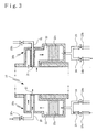
- a subject material 1 formed of a steel material is introduced into a heating furnace 10 through an inlet 11 of the heating furnace 10.
- the subject material is heat treated while being transported by a walking beam 2 through the heating furnace 10.
- the subject material 1 thus heat treated is taken out of the heating furnace 10 through an outlet 12 of the heating furnace 10.
- the heating furnace 10 is provided with plural pairs of regenerative burners 20 arranged in a moving direction of the subject material 1.
- the paired regenerative burners 20 are disposed in face-to-face relation.
- the regenerative burner 20 includes a burner portion 21 and a regenerator 22.
- one regenerative burner 20a of the pair opens an air feeding valve 23a which is disposed in an air feed pipe 23 for feeding a combustion air to the regenerator 22 accommodating a heat storage material 22a therein.
- a gas discharging valve 24a is closed, which valve is disposed in an exhaust gas discharge pipe 24 for discharging a combustion exhaust gas via the regenerator 22.
- the combustion air introduced into the regenerator 22 through the air feed pipe 23 is heated by means of the heat storage material 22a accommodated in this regenerator 22.
- the combustion air thus heated is fed to the burner portion 21 while a fuel gas is injected from a fuel injection nozzle 25 by opening a gas feeding valve 25a for feeding the fuel gas to the fuel injection nozzle 25 disposed at this burner portion 21.
- a gas feeding valve 25a for feeding the fuel gas to the fuel injection nozzle 25 disposed at this burner portion 21.
- the fuel gas is combusted in the heating furnace 10
- the combusting operation is disabled by closing a gas feeding valve 25b for feeding the fuel gas to the fuel injection nozzle 25 and closing an air feeding valve 23b disposed in the air feed pipe 23.
- a gas discharging valve 24b disposed in the exhaust gas discharge pipe 24 is opened, the exhaust gas discharge pipe serving to discharge the combustion exhaust gas via the regenerator 22.
- the combustion exhaust gas resulting from the combustion in the heating furnace 10 is sucked into the regenerator 22 so as to allow the heat storage material 22a accommodated in the regenerator 22 to store heat from the combustion exhaust gas.
- the combustion exhaust gas is discharged to the outside via the exhaust gas discharge pipe 24.
- the one regenerative burner 20a performs the combusting operation by injecting the fuel gas from the fuel injection nozzle 25 while the other regenerative burner 20b introduces the combustion exhaust gas into the regenerator 22 and allows the heat storage material 22b to store the heat from the combustion exhaust gas before discharging the combustion exhaust gas.
- These regenerative burners are switched to alternate between these operations.
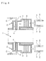
- the combusting operation is stopped by closing the air feeding valve 23a and the gas feeding valve 25a so as to inhibit the supply of combustion air and fuel gas.
- the gas discharging valve 24b is closed while the air feeding valve 23b is temporarily opened for temporary supply of the combustion air through the air feed pipe 23.
- the combustion exhaust gas remaining in the regenerator 22 or the exhaust gas discharge pipe 24 and the like is discharged into the heating furnace 10 by means of the combustion air thus supplied.
- the above gas feeding valve 25b is temporarily opened for temporary injection of the fuel gas from this fuel injection nozzle 25 so that the fuel gas and the combustion air supplied as described above are temporarily combusted.
- the regenerative burner 20b After temporarily combusting the fuel gas and combustion air in this manner, the regenerative burner 20b stops the combusting operation by closing the air feeding valve 23b and the gas feeding valve 25b so as to inhibit the supply of the combustion air and fuel gas.
- This approach prevents the acid production from the cooled combustion exhaust gas, which remains in the regenerator 22, the exhaust gas discharge pipe 24 and the like of the regenerative burner 20b which is performing, at the time of operation stop, the operation of introducing the combustion exhaust gas into the regenerator 22 and allowing the heat storage material 22b to store the heat from the combustion exhaust gas before discharging the combustion exhaust gas, as described above.
- the inside of the regenerator 22, the exhaust gas discharge pipe 24 and the like is corroded with the acid.
- the combustion air temporarily supplied is combusted together with the fuel gas, as described above, whereby the increase in oxygen partial pressure in the heating furnace 10 is prevented to ensure that the stable heat treatment is carried out.
- the time in which the combustion air is temporarily supplied to the regenerative burner 20b which is performing, at the time of operation stop, the operation of introducing the combustion exhaust gas into the regenerator 22 and allowing the heat storage material 22b to store the heat from the combustion exhaust gas before discharging the combustion exhaust gas is preferably defined to be long enough to flow a sufficient amount of combustion air for discharging the remaining combustion exhaust gas from the regenerator 22 into the heating furnace 10.
- the above time is preferably defined to be long enough to flow the combustion air at least in a volume given by subtracting the volume of the heat storage material 22b from the volume of the regenerator 22.
- the regenerative burner 20b temporarily injects the fuel gas from the fuel injection nozzle 25 and temporarily combusts the fuel gas together with the combustion air supplied thereto as described above, it is preferred that the fuel gas and the combustion air are supplied simultaneously. In addition, it is more preferred to maintain flow rates of the fuel gas and the combustion air at levels just prior to the operation stop.
- the combustion air is temporarily supplied, as described above, to the regenerative burner 20b which is performing, at the time of operation stop, the operation of introducing the combustion exhaust gas into the regenerator 22 and allowing the heat storage material 22b to store the heat from the combustion exhaust gas before discharging the combustion exhaust gas, so that the combustion exhaust gas remaining in the regenerator 22, the exhaust gas discharge pipe 24 and the like is discharged into the heating furnace 10 by way of the combustion air.
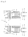
- the air feeding valve 23b is temporarily opened for temporary supply of the combustion air through the air feed pipe 23 while the gas discharging valve 24b is opened to allow the temporarily supplied combustion air to discharge the remaining combustion exhaust gas from the exhaust gas discharge pipe 24 to the outside of the furnace via the exhaust gas discharge pipe 24. This approach ensures that the combustion exhaust gas remaining in the gas discharge pipe 24 is more reliably discharged.
- the regenerative burner 20a performing, at the time of operation stop, the combusting operation by injecting the fuel gas from the fuel injection nozzle 25 also takes the same procedure as the regenerative burner 20b in order that the combustion exhaust gas remaining in the exhaust gas discharge pipe 24 is more reliably discharged.
- the air feeding valve 23a is temporarily opened for temporary supply of the combustion air through the air feed pipe 23 while the gas discharging valve 24a is opened to allow the temporarily supplied combustion air to discharge the remaining combustion exhaust gas from the exhaust gas discharge pipe 24 to the outside of the furnace via the exhaust gas discharge pipe 24.
- the time in which the combustion air is temporarily supplied is defined to be long enough to flow a sufficient amount of combustion air for diluting the combustion exhaust gas in the exhaust gas discharge pipe 24 to such a degree as to eliminate the fear that the acid causing the corrosion at the inside of the exhaust gas discharge pipe 24 is produced from the combustion exhaust gas.
Landscapes
- Engineering & Computer Science (AREA)
- Chemical & Material Sciences (AREA)
- Combustion & Propulsion (AREA)
- Mechanical Engineering (AREA)
- General Engineering & Computer Science (AREA)
- Materials Engineering (AREA)
- Organic Chemistry (AREA)
- Air Supply (AREA)
Applications Claiming Priority (1)
| Application Number | Priority Date | Filing Date | Title |
|---|---|---|---|
| JP2009007447A JP4638947B2 (ja) | 2009-01-16 | 2009-01-16 | 蓄熱燃焼式加熱炉の燃焼制御方法 |
Publications (3)
| Publication Number | Publication Date |
|---|---|
| EP2208929A2 true EP2208929A2 (fr) | 2010-07-21 |
| EP2208929A3 EP2208929A3 (fr) | 2010-12-22 |
| EP2208929B1 EP2208929B1 (fr) | 2015-02-11 |
Family
ID=42102022
Family Applications (1)
| Application Number | Title | Priority Date | Filing Date |
|---|---|---|---|
| EP09015900.5A Not-in-force EP2208929B1 (fr) | 2009-01-16 | 2009-12-22 | Procédé de combustion pour un four à régénération |
Country Status (6)
| Country | Link |
|---|---|
| EP (1) | EP2208929B1 (fr) |
| JP (1) | JP4638947B2 (fr) |
| KR (1) | KR101019367B1 (fr) |
| CN (1) | CN101782326B (fr) |
| ES (1) | ES2535221T3 (fr) |
| TW (1) | TWI346761B (fr) |
Families Citing this family (6)
| Publication number | Priority date | Publication date | Assignee | Title |
|---|---|---|---|---|
| JP5495378B2 (ja) * | 2010-03-01 | 2014-05-21 | 新日鉄住金エンジニアリング株式会社 | 排ガス用配管のパージ方法及びパージ装置 |
| JP5795552B2 (ja) * | 2012-05-22 | 2015-10-14 | 中外炉工業株式会社 | 蓄熱ユニット |
| JP5752156B2 (ja) * | 2013-01-29 | 2015-07-22 | 中外炉工業株式会社 | 燃焼装置の燃焼制御方法 |
| CN103968668B (zh) * | 2014-04-24 | 2016-04-06 | 深圳市中创达热工技术有限公司 | 一种固体燃料熔炉 |
| JP6483169B2 (ja) * | 2017-02-14 | 2019-03-13 | 中外炉工業株式会社 | リジェネレイティブバーナの燃料ノズル冷却構造 |
| JP6545739B2 (ja) * | 2017-03-03 | 2019-07-17 | 中外炉工業株式会社 | 蓄熱式バーナシステム |
Citations (2)
| Publication number | Priority date | Publication date | Assignee | Title |
|---|---|---|---|---|
| EP0136175A2 (fr) | 1983-09-28 | 1985-04-03 | National Research Development Corporation | Système d'échange thermique par régénération |
| JPH07103668A (ja) | 1993-09-30 | 1995-04-18 | Nkk Corp | 蓄熱型燃焼器 |
Family Cites Families (3)
| Publication number | Priority date | Publication date | Assignee | Title |
|---|---|---|---|---|
| US5823769A (en) | 1996-03-26 | 1998-10-20 | Combustion Tec, Inc. | In-line method of burner firing and NOx emission control for glass melting |
| JP2001141233A (ja) * | 1999-11-16 | 2001-05-25 | Tokyo Gas Co Ltd | 蓄熱式バーナシステム |
| JP4349954B2 (ja) * | 2004-03-26 | 2009-10-21 | 新日本製鐵株式会社 | 蓄熱式バーナ加熱炉の操業方法 |
-
2009
- 2009-01-16 JP JP2009007447A patent/JP4638947B2/ja active Active
- 2009-12-17 KR KR1020090125902A patent/KR101019367B1/ko active Active
- 2009-12-21 CN CN2009102659506A patent/CN101782326B/zh not_active Expired - Fee Related
- 2009-12-22 EP EP09015900.5A patent/EP2208929B1/fr not_active Not-in-force
- 2009-12-22 ES ES09015900.5T patent/ES2535221T3/es active Active
-
2010
- 2010-01-05 TW TW099100063A patent/TWI346761B/zh active
Patent Citations (2)
| Publication number | Priority date | Publication date | Assignee | Title |
|---|---|---|---|---|
| EP0136175A2 (fr) | 1983-09-28 | 1985-04-03 | National Research Development Corporation | Système d'échange thermique par régénération |
| JPH07103668A (ja) | 1993-09-30 | 1995-04-18 | Nkk Corp | 蓄熱型燃焼器 |
Also Published As
| Publication number | Publication date |
|---|---|
| JP2010164256A (ja) | 2010-07-29 |
| EP2208929A3 (fr) | 2010-12-22 |
| CN101782326A (zh) | 2010-07-21 |
| TWI346761B (en) | 2011-08-11 |
| KR20100084464A (ko) | 2010-07-26 |
| KR101019367B1 (ko) | 2011-03-07 |
| JP4638947B2 (ja) | 2011-02-23 |
| CN101782326B (zh) | 2012-12-26 |
| ES2535221T3 (es) | 2015-05-07 |
| EP2208929B1 (fr) | 2015-02-11 |
| TW201028618A (en) | 2010-08-01 |
Similar Documents
| Publication | Publication Date | Title |
|---|---|---|
| EP2208929A2 (fr) | Procédé de combustion pour un four à régénération | |
| EP2199677A2 (fr) | Procédé de contrôle de combustion pour four à traitement thermique à combustion régénérative | |
| EP2687283B1 (fr) | Installation et procédé de traitement de gaz avec régénération, pour échangeur interne à la régénération. | |
| EP2742990A1 (fr) | Installation et procédé de traitement de gaz avec régénération et recyclage de gaz issu de la régénération. | |
| CN102269518B (zh) | 蓄热燃烧式热处理炉的燃烧控制方法 | |
| JP4615045B2 (ja) | 蓄熱燃焼式熱処理炉の燃焼制御方法 | |
| JP2012112588A (ja) | 加熱炉 | |
| JP5398685B2 (ja) | 加熱炉における蓄熱式バーナの燃焼制御方法 | |
| JP2014048020A (ja) | 連続式加熱炉 | |
| JP5772477B2 (ja) | 連続式加熱炉用放炎防止装置および放炎防止方法 | |
| KR102381603B1 (ko) | 용사보수 버너장치의 공급가스 제어시스템 및 방법 | |
| KR102482855B1 (ko) | 유리화설비의 폐기물 공급장치 | |
| KR101372631B1 (ko) | 축열 연소식 열처리로의 연소 제어 방법 | |
| CN119042646A (zh) | 用于油田的rto系统及废气处理方法 | |
| KR20200064532A (ko) | 부생가스 처리장치 | |
| JPH08285218A (ja) | 加熱炉における低NOx燃焼方法 | |
| KR20040054084A (ko) | 화학적 기상 증착 장치의 연동 밸브 시스템 |
Legal Events
| Date | Code | Title | Description |
|---|---|---|---|
| PUAI | Public reference made under article 153(3) epc to a published international application that has entered the european phase |
Free format text: ORIGINAL CODE: 0009012 |
|
| AK | Designated contracting states |
Kind code of ref document: A2 Designated state(s): AT BE BG CH CY CZ DE DK EE ES FI FR GB GR HR HU IE IS IT LI LT LU LV MC MK MT NL NO PL PT RO SE SI SK SM TR |
|
| AX | Request for extension of the european patent |
Extension state: AL BA RS |
|
| PUAL | Search report despatched |
Free format text: ORIGINAL CODE: 0009013 |
|
| AK | Designated contracting states |
Kind code of ref document: A3 Designated state(s): AT BE BG CH CY CZ DE DK EE ES FI FR GB GR HR HU IE IS IT LI LT LU LV MC MK MT NL NO PL PT RO SE SI SK SM TR |
|
| AX | Request for extension of the european patent |
Extension state: AL BA RS |
|
| 17P | Request for examination filed |
Effective date: 20110503 |
|
| GRAP | Despatch of communication of intention to grant a patent |
Free format text: ORIGINAL CODE: EPIDOSNIGR1 |
|
| INTG | Intention to grant announced |
Effective date: 20140818 |
|
| GRAS | Grant fee paid |
Free format text: ORIGINAL CODE: EPIDOSNIGR3 |
|
| GRAA | (expected) grant |
Free format text: ORIGINAL CODE: 0009210 |
|
| AK | Designated contracting states |
Kind code of ref document: B1 Designated state(s): AT BE BG CH CY CZ DE DK EE ES FI FR GB GR HR HU IE IS IT LI LT LU LV MC MK MT NL NO PL PT RO SE SI SK SM TR |
|
| REG | Reference to a national code |
Ref country code: GB Ref legal event code: FG4D |
|
| REG | Reference to a national code |
Ref country code: CH Ref legal event code: EP |
|
| REG | Reference to a national code |
Ref country code: IE Ref legal event code: FG4D |
|
| REG | Reference to a national code |
Ref country code: AT Ref legal event code: REF Ref document number: 710053 Country of ref document: AT Kind code of ref document: T Effective date: 20150315 |
|
| REG | Reference to a national code |
Ref country code: SE Ref legal event code: TRGR |
|
| REG | Reference to a national code |
Ref country code: DE Ref legal event code: R096 Ref document number: 602009029316 Country of ref document: DE Effective date: 20150319 |
|
| REG | Reference to a national code |
Ref country code: ES Ref legal event code: FG2A Ref document number: 2535221 Country of ref document: ES Kind code of ref document: T3 Effective date: 20150507 |
|
| REG | Reference to a national code |
Ref country code: NL Ref legal event code: VDEP Effective date: 20150211 |
|
| REG | Reference to a national code |
Ref country code: AT Ref legal event code: MK05 Ref document number: 710053 Country of ref document: AT Kind code of ref document: T Effective date: 20150211 |
|
| REG | Reference to a national code |
Ref country code: LT Ref legal event code: MG4D |
|
| PG25 | Lapsed in a contracting state [announced via postgrant information from national office to epo] |
Ref country code: NO Free format text: LAPSE BECAUSE OF FAILURE TO SUBMIT A TRANSLATION OF THE DESCRIPTION OR TO PAY THE FEE WITHIN THE PRESCRIBED TIME-LIMIT Effective date: 20150511 Ref country code: HR Free format text: LAPSE BECAUSE OF FAILURE TO SUBMIT A TRANSLATION OF THE DESCRIPTION OR TO PAY THE FEE WITHIN THE PRESCRIBED TIME-LIMIT Effective date: 20150211 Ref country code: LT Free format text: LAPSE BECAUSE OF FAILURE TO SUBMIT A TRANSLATION OF THE DESCRIPTION OR TO PAY THE FEE WITHIN THE PRESCRIBED TIME-LIMIT Effective date: 20150211 |
|
| PG25 | Lapsed in a contracting state [announced via postgrant information from national office to epo] |
Ref country code: GR Free format text: LAPSE BECAUSE OF FAILURE TO SUBMIT A TRANSLATION OF THE DESCRIPTION OR TO PAY THE FEE WITHIN THE PRESCRIBED TIME-LIMIT Effective date: 20150512 Ref country code: AT Free format text: LAPSE BECAUSE OF FAILURE TO SUBMIT A TRANSLATION OF THE DESCRIPTION OR TO PAY THE FEE WITHIN THE PRESCRIBED TIME-LIMIT Effective date: 20150211 Ref country code: LV Free format text: LAPSE BECAUSE OF FAILURE TO SUBMIT A TRANSLATION OF THE DESCRIPTION OR TO PAY THE FEE WITHIN THE PRESCRIBED TIME-LIMIT Effective date: 20150211 Ref country code: IS Free format text: LAPSE BECAUSE OF FAILURE TO SUBMIT A TRANSLATION OF THE DESCRIPTION OR TO PAY THE FEE WITHIN THE PRESCRIBED TIME-LIMIT Effective date: 20150611 Ref country code: NL Free format text: LAPSE BECAUSE OF FAILURE TO SUBMIT A TRANSLATION OF THE DESCRIPTION OR TO PAY THE FEE WITHIN THE PRESCRIBED TIME-LIMIT Effective date: 20150211 |
|
| PG25 | Lapsed in a contracting state [announced via postgrant information from national office to epo] |
Ref country code: DK Free format text: LAPSE BECAUSE OF FAILURE TO SUBMIT A TRANSLATION OF THE DESCRIPTION OR TO PAY THE FEE WITHIN THE PRESCRIBED TIME-LIMIT Effective date: 20150211 Ref country code: SK Free format text: LAPSE BECAUSE OF FAILURE TO SUBMIT A TRANSLATION OF THE DESCRIPTION OR TO PAY THE FEE WITHIN THE PRESCRIBED TIME-LIMIT Effective date: 20150211 Ref country code: EE Free format text: LAPSE BECAUSE OF FAILURE TO SUBMIT A TRANSLATION OF THE DESCRIPTION OR TO PAY THE FEE WITHIN THE PRESCRIBED TIME-LIMIT Effective date: 20150211 Ref country code: CZ Free format text: LAPSE BECAUSE OF FAILURE TO SUBMIT A TRANSLATION OF THE DESCRIPTION OR TO PAY THE FEE WITHIN THE PRESCRIBED TIME-LIMIT Effective date: 20150211 Ref country code: RO Free format text: LAPSE BECAUSE OF FAILURE TO SUBMIT A TRANSLATION OF THE DESCRIPTION OR TO PAY THE FEE WITHIN THE PRESCRIBED TIME-LIMIT Effective date: 20150211 |
|
| REG | Reference to a national code |
Ref country code: DE Ref legal event code: R097 Ref document number: 602009029316 Country of ref document: DE |
|
| PG25 | Lapsed in a contracting state [announced via postgrant information from national office to epo] |
Ref country code: PL Free format text: LAPSE BECAUSE OF FAILURE TO SUBMIT A TRANSLATION OF THE DESCRIPTION OR TO PAY THE FEE WITHIN THE PRESCRIBED TIME-LIMIT Effective date: 20150211 |
|
| PLBE | No opposition filed within time limit |
Free format text: ORIGINAL CODE: 0009261 |
|
| STAA | Information on the status of an ep patent application or granted ep patent |
Free format text: STATUS: NO OPPOSITION FILED WITHIN TIME LIMIT |
|
| PG25 | Lapsed in a contracting state [announced via postgrant information from national office to epo] |
Ref country code: IT Free format text: LAPSE BECAUSE OF FAILURE TO SUBMIT A TRANSLATION OF THE DESCRIPTION OR TO PAY THE FEE WITHIN THE PRESCRIBED TIME-LIMIT Effective date: 20150211 |
|
| 26N | No opposition filed |
Effective date: 20151112 |
|
| PG25 | Lapsed in a contracting state [announced via postgrant information from national office to epo] |
Ref country code: SI Free format text: LAPSE BECAUSE OF FAILURE TO SUBMIT A TRANSLATION OF THE DESCRIPTION OR TO PAY THE FEE WITHIN THE PRESCRIBED TIME-LIMIT Effective date: 20150211 |
|
| PGFP | Annual fee paid to national office [announced via postgrant information from national office to epo] |
Ref country code: SE Payment date: 20151222 Year of fee payment: 7 Ref country code: ES Payment date: 20151218 Year of fee payment: 7 |
|
| PG25 | Lapsed in a contracting state [announced via postgrant information from national office to epo] |
Ref country code: BE Free format text: LAPSE BECAUSE OF FAILURE TO SUBMIT A TRANSLATION OF THE DESCRIPTION OR TO PAY THE FEE WITHIN THE PRESCRIBED TIME-LIMIT Effective date: 20150211 |
|
| REG | Reference to a national code |
Ref country code: DE Ref legal event code: R119 Ref document number: 602009029316 Country of ref document: DE |
|
| PG25 | Lapsed in a contracting state [announced via postgrant information from national office to epo] |
Ref country code: LU Free format text: LAPSE BECAUSE OF FAILURE TO SUBMIT A TRANSLATION OF THE DESCRIPTION OR TO PAY THE FEE WITHIN THE PRESCRIBED TIME-LIMIT Effective date: 20151222 Ref country code: MC Free format text: LAPSE BECAUSE OF FAILURE TO SUBMIT A TRANSLATION OF THE DESCRIPTION OR TO PAY THE FEE WITHIN THE PRESCRIBED TIME-LIMIT Effective date: 20150211 |
|
| REG | Reference to a national code |
Ref country code: CH Ref legal event code: PL |
|
| GBPC | Gb: european patent ceased through non-payment of renewal fee |
Effective date: 20151222 |
|
| REG | Reference to a national code |
Ref country code: IE Ref legal event code: MM4A |
|
| REG | Reference to a national code |
Ref country code: FR Ref legal event code: ST Effective date: 20160831 |
|
| PG25 | Lapsed in a contracting state [announced via postgrant information from national office to epo] |
Ref country code: LI Free format text: LAPSE BECAUSE OF NON-PAYMENT OF DUE FEES Effective date: 20151231 Ref country code: IE Free format text: LAPSE BECAUSE OF NON-PAYMENT OF DUE FEES Effective date: 20151222 Ref country code: GB Free format text: LAPSE BECAUSE OF NON-PAYMENT OF DUE FEES Effective date: 20151222 Ref country code: CH Free format text: LAPSE BECAUSE OF NON-PAYMENT OF DUE FEES Effective date: 20151231 Ref country code: DE Free format text: LAPSE BECAUSE OF NON-PAYMENT OF DUE FEES Effective date: 20160701 |
|
| PG25 | Lapsed in a contracting state [announced via postgrant information from national office to epo] |
Ref country code: FR Free format text: LAPSE BECAUSE OF NON-PAYMENT OF DUE FEES Effective date: 20151231 |
|
| PG25 | Lapsed in a contracting state [announced via postgrant information from national office to epo] |
Ref country code: HU Free format text: LAPSE BECAUSE OF FAILURE TO SUBMIT A TRANSLATION OF THE DESCRIPTION OR TO PAY THE FEE WITHIN THE PRESCRIBED TIME-LIMIT; INVALID AB INITIO Effective date: 20091222 Ref country code: SM Free format text: LAPSE BECAUSE OF FAILURE TO SUBMIT A TRANSLATION OF THE DESCRIPTION OR TO PAY THE FEE WITHIN THE PRESCRIBED TIME-LIMIT Effective date: 20150211 Ref country code: BG Free format text: LAPSE BECAUSE OF FAILURE TO SUBMIT A TRANSLATION OF THE DESCRIPTION OR TO PAY THE FEE WITHIN THE PRESCRIBED TIME-LIMIT Effective date: 20150211 |
|
| PG25 | Lapsed in a contracting state [announced via postgrant information from national office to epo] |
Ref country code: CY Free format text: LAPSE BECAUSE OF FAILURE TO SUBMIT A TRANSLATION OF THE DESCRIPTION OR TO PAY THE FEE WITHIN THE PRESCRIBED TIME-LIMIT Effective date: 20150211 |
|
| REG | Reference to a national code |
Ref country code: SE Ref legal event code: EUG |
|
| PG25 | Lapsed in a contracting state [announced via postgrant information from national office to epo] |
Ref country code: MT Free format text: LAPSE BECAUSE OF FAILURE TO SUBMIT A TRANSLATION OF THE DESCRIPTION OR TO PAY THE FEE WITHIN THE PRESCRIBED TIME-LIMIT Effective date: 20150211 Ref country code: SE Free format text: LAPSE BECAUSE OF NON-PAYMENT OF DUE FEES Effective date: 20161223 Ref country code: TR Free format text: LAPSE BECAUSE OF FAILURE TO SUBMIT A TRANSLATION OF THE DESCRIPTION OR TO PAY THE FEE WITHIN THE PRESCRIBED TIME-LIMIT Effective date: 20150211 |
|
| PG25 | Lapsed in a contracting state [announced via postgrant information from national office to epo] |
Ref country code: ES Free format text: LAPSE BECAUSE OF NON-PAYMENT OF DUE FEES Effective date: 20161223 |
|
| PG25 | Lapsed in a contracting state [announced via postgrant information from national office to epo] |
Ref country code: PT Free format text: LAPSE BECAUSE OF FAILURE TO SUBMIT A TRANSLATION OF THE DESCRIPTION OR TO PAY THE FEE WITHIN THE PRESCRIBED TIME-LIMIT Effective date: 20150211 Ref country code: MK Free format text: LAPSE BECAUSE OF FAILURE TO SUBMIT A TRANSLATION OF THE DESCRIPTION OR TO PAY THE FEE WITHIN THE PRESCRIBED TIME-LIMIT Effective date: 20150211 |
|
| REG | Reference to a national code |
Ref country code: ES Ref legal event code: FD2A Effective date: 20181112 |
|
| PGFP | Annual fee paid to national office [announced via postgrant information from national office to epo] |
Ref country code: FI Payment date: 20181213 Year of fee payment: 10 |
|
| REG | Reference to a national code |
Ref country code: FI Ref legal event code: MAE |
|
| PG25 | Lapsed in a contracting state [announced via postgrant information from national office to epo] |
Ref country code: FI Free format text: LAPSE BECAUSE OF NON-PAYMENT OF DUE FEES Effective date: 20191222 |