EP2208960B1 - Langloch-montierte Zielvorrichtung - Google Patents
Langloch-montierte Zielvorrichtung Download PDFInfo
- Publication number
- EP2208960B1 EP2208960B1 EP09169476.0A EP09169476A EP2208960B1 EP 2208960 B1 EP2208960 B1 EP 2208960B1 EP 09169476 A EP09169476 A EP 09169476A EP 2208960 B1 EP2208960 B1 EP 2208960B1
- Authority
- EP
- European Patent Office
- Prior art keywords
- laser
- gun
- light source
- housing
- canister
- Prior art date
- Legal status (The legal status is an assumption and is not a legal conclusion. Google has not performed a legal analysis and makes no representation as to the accuracy of the status listed.)
- Active
Links
Images




Classifications
-
- F—MECHANICAL ENGINEERING; LIGHTING; HEATING; WEAPONS; BLASTING
- F41—WEAPONS
- F41G—WEAPON SIGHTS; AIMING
- F41G11/00—Details of sighting or aiming apparatus; Accessories
- F41G11/001—Means for mounting sighting or aiming devices on firearms
- F41G11/003—Mountings with a dove tail element, e.g. "Picatinny rail systems"
-
- F—MECHANICAL ENGINEERING; LIGHTING; HEATING; WEAPONS; BLASTING
- F41—WEAPONS
- F41G—WEAPON SIGHTS; AIMING
- F41G1/00—Sighting devices
- F41G1/32—Night sights, e.g. luminescent
- F41G1/34—Night sights, e.g. luminescent combined with light source, e.g. spot light
- F41G1/35—Night sights, e.g. luminescent combined with light source, e.g. spot light for illuminating the target
Definitions
- the present invention relates to a light-emitting sighting device, the weapon preferably being a gun.
- a light beam such as a laser beam
- Lasers are the preferred means of generating light beams for weapon sighting because they have comparatively high intensity and can be focused into a narrow beam with a very small divergence angle so they produce a small, bright spot on a target.
- the laser projects a narrow beam of light in a direction generally parallel to the gun's bore. When the light beam and bore are properly aligned, the bullet (or other projectile) will hit on or very close to the location of the light beam projected on a target.
- a sighting device of the prior art is known from US 4,939,863 A1 .
- laser includes any form of laser light source, and the term “laser sight” refers to a light emitting module or assembly that projects a beam of light having a small divergence angle suitable for weapon alignment or sighting purposes.
- a laser sight It is known to attach a laser sight to the trigger guard of a hand gun or other weapon.
- trigger-guard mounted laser sights are known.
- a problem associated with trigger-guard mounted laser sights is that trigger guards are complex, three-dimensional shapes with non-uniform cross-sections and it is difficult to mount, align and use the laser light.
- US patent 2005/241209 discloses a device having a structure that can support the device on a weapon. The device includes a first sight for facilitating weapon orientation in preparation to fire a first munition and a second sight for facilitating weapon orientation in preparation to fire a second munition.
- the invention is a sighting device for a gun according to claim 1.
- the mechanical sight may include a sighting insert, preferably the sighting insert is luminescent.
- the device of claim 1 further may include a secondary light source, preferably the secondary light source may be spaced apart from the laser; or there may be a mechanical sight between the laser and the secondary source, preferably the secondary light source may be an infra-red light; a flashlight, preferably an LED flashlight; or a visible light laser or an infra-red laser.
- the device of claim 1 may further include a secondary light source or in the device the laser and secondary light source may be each connectable to the power source or the laser and the secondary light source may simultaneously omit light.
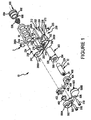
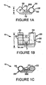
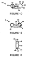
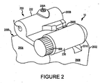
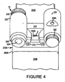
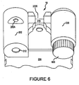
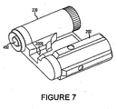
- Figures 1-11 show a preferred embodiment of a device 10 according to the invention.
- Device 10 has a laser.
- device 10 is configured to be mounted in a slot formed in the top surface of a gun, wherein device 10 provides a lighting source and preferably still allows a user to mechanically sight the gun.
- the slot (best seen in Figures 9 and 13 ) 2010 is known to those skilled in the art (if the slot is on the top surface of the gun it preferably extends the entire width of the top surface), and in one embodiment (for a Glock 19 pistol) is 1" (2,54cm) wide and .080" (2.032 cm) deep.
- Device 10 could also be mounted to the top, rear portion or side, rear portion of a gun in any other suitable, fashion that allows the gun to be properly holstered in a standard holster (i.e., one not specially made to accommodate the device, but made solely to holster the gun) and that allows the light source to be projected along a side surface of the gun or along the top surface of the gun.
- a standard holster i.e., one not specially made to accommodate the device, but made solely to holster the gun
- device 10 could be mounted to the gun using a U-shaped or L-shaped bracket.
- When mounted on a gun device 10 preferably extends no farther from the back of the gun than about 2 1/2" (6.35 cm), 2" (5.08 cm), 1 1/2" (3.81 cm) or 1 1/4" (3.175 cm) and extends outward from the top surface or side surface of the gun no further than about 3/4" (1.905 cm), 1/2" (1,27cm), 3/8" (0.9525 cm) or .313" (0.795 cm).
- Device 10 preferably has an entire length L (seen best in Figure 1B ) of less than 3" (3.175 cm), or less than 2"(5.08 cm), or less than 1 1/2"(3.81 cm), less than 1" (2,54cm) and preferably about .875" (2.2225 cm), and preferably has a height H (seen best in Figure 1A ) of less than 3/4"(1.905 cm), or less than 1/2" (1,27cm) and preferably about 3/8"(0.9525 cm).
- Device 10 includes a light source 20, a power source 30 and a housing 200 that includes a mount 102, which as shown is a bottom rail that fits into a slot formed on a gun.
- Light source 20 has a first end 20A (through which light can be emitted), is a visible-light laser module.
- light source 20 is a red-light, 650 nanometer, 3.3 mm diode, visible laser
- the laser module has an overall length of about 14 mm and a diameter of about 4.5 mm. It includes a 3 mm focal length, collimating lens. Any suitable laser/laser module may be used, however.
- a biasing spring 24 is attached to second end 20B to bias light source 20 towards first end 20A when device 10 is assembled.
- Power source 30 can be any suitable power source for light source 20, and is preferably an electric power source and most preferably a portable, electrical power source such as a battery or multiple batteries.
- the embodiment shown uses four 1-3 silver oxide 1.5V silver oxide LR626 batteries 32, although any suitable batteries or other power source may be used.
- Device 10 as shown further includes a housing 200, a light source adjustment apparatus 300, an integrated circuit board 400, a backing 500, and a battery cap 600.
- the purpose of housing 200 is to retain light source 20 and power source 30 and mount them to a gun, and to selectively connect power source 30 to light source 20. Any suitable structure or structures may be used for this purpose.
- Housing 200 is preferably made of metal injection molded stainless steel (MIM), but could be made of any suitable material, such as another metal (for example, MIM carbon steel or extruded aluminum) or plastic.
- Housing 200 has a first end 200A, a second end 200B and includes a first canister 202 and a second canister 230.
- First canister 202 is configured to receive and retain the light source 20 (which is a laser module), which as shown is first positioned in light source adjustment apparatus 300. Once so positioned, apparatus 300, with light source 20 inside, is positioned in and retained in canister 202.
- canister 202 has an outer surface 204, a first rib 206, a second rib 208, an inner cavity 210 in which apparatus 300 and light source 20 are retained, and an opening 212 through which the light source 20 can emit light.
- Canister 202 also includes an aperture 206A that extends through rib 206 to inner cavity 210 and an aperture 208A that extends through rib 208 to inner cavity 210.
- Each of apertures 206A and 208A are configured to receive a moveable screw or screw 225 (hereafter referred to as "set screw” or “set screws,” which are preferably socket-head set screws).
- rib 206 and rib 208 are to provide additional area to support set screws 225.
- a raised portion may be used in place of rib 206 and/or 208.
- Other structures may be used for this purpose or no such structure may be used.
- Second canister 230 as shown is spaced apart from first canister 202 and is configured to receive and retain the power source 30.
- Canister 230 as shown has an outer surface 234, an inner cavity 240, a first end 242 and a second end 244.
- Second end 244 is configured to open in order to add or change power source 30.
- second end 244 includes internal threads (not shown) that mate with threads on power source retention cap 600 to allow cap 600 to be screwed onto end 244 and screwed off of end 244 in order to add or remove power source 30 from canister 230.
- Housing 200 also includes a connective portion 270 that connects first canister 202 and second canister 230.
- Connective portion 270 has a bottom surface 272 and a mount 102 attached to or integrally formed with bottom surface 272.
- Mount 102 is for mechanically attaching device 10 to a gun and any suitable structure or structures may be used for this purpose.
- mount 274 is a generally a rail configured to be received in the slot (which may have a dovetail shape) formed on a gun.
- An aperture (not shown) may be formed in housing 200, in connective portion 270.
- a set screw 2 is received in the aperture and tightened so that it creates a pressure fit against a surface (preferably the base of a slot) of the gun to assist in retaining the device on the gun.
- An opening 200S is formed in housing 200 to create a mechanical sight that, in this embodiment, forms the rear, mechanical sight for a gun to which device 10 is mounted.
- the rear mechanical sight is visually aligned with the front mechanical sight to properly sight a gun.
- an apparatus including a gun with device 10 attached can be sighted using light source 20.
- Light source adjustment apparatus (or “LSAA”) 300 is for retaining the light source 20 when it is positioned in housing 200 and for assisting in positioning light source 20.
- LSAA 300 serves two purposes: (1) it absorbs the recoil of a gun to which device 10 is mounted thereby enabling light source 20 to remain in a relatively stable position, and (2) it enables a user to adjust the position of light source 20.
- LSAA 300 is generally conical with a first, smaller diameter end 302 and a second, large diameter end 304. It is preferably comprised of an elastomeric material, such as neoprene rubber, of about a 60 Shore A to absorb shock, but can be made of any suitable material. It has an opening 308 configured to receive light source 20.
- LSAA 300 fits into inner cavity 210 of first canister 202.
- LSAA 300 is shaped to be biased towards apertures 206A and 208A and, as one or both set screws 225 are tightened, the set screw(s) pushes against LSAA 300 and moves it (in this embodiment) either to the side and/or downward thereby adjusting the position of light source 20.
- Integrated circuit board 400 is configured to be received and mounted on second end 200B of housing 200.
- the basic purpose of board 400 is to connect the power source 30 to the light source 20 and any suitable structure or device can be used for this purpose.
- Board 400 is preferably plastic and includes a push button switch 402, an integrated circuit 404 and two through screw holes 406. Current is transferred via board 400 to laser module 20.
- Board 400 is designed for negative switching wherein power is generated from the negative side of power source 30 (which are batteries in this embodiment) and through spring 24 of light source 20 in this embodiment.
- Integrated circuit 404 allows for the pulsed delivery of power to light source 20 (preferably about 1,000 cycles per second, and preferably pulsing at a 50% on duty rate) in order to save power and power source life, although the delivery of power need not be pulsed, or can be pulsed in any suitable manner.
- the light source has between a 8 and 15 milliamp draw, and most preferably less than a 10 milliamp draw, of current when in use and utilizing the 1,000 pulses per minute delivery of current to light source 20.
- a button 450 is of any suitable shape to fit with push button switch 402 and backing 500, described below.
- Button 450 is for enabling a user to selectively activate switch 402 thus turning the light source 20 off and on, and any suitable device or structure can be used for this purpose.
- Backing 500 is preferably plastic and its purpose is to hold integrated circuit board 400 to housing 200 and to protect integrated circuit board 400 and the other components inside of housing 200.
- Backing 500 has a first side 500A configured to fit over canister 202 at end 200B and a second side 500B configured to fit over end 242 of canister 230. It further includes an opening 502 through which button 450 projects so it can be pressed by a user to turn light source 20 on and off, and openings 506 that align with screw holes 406 and screw retainers 250. Screws 510 are then received through openings 506 and screw holes 406, and are threaded into retainers 250 to hold device 10 together.
- Power source retention cap 600 has a threaded end 602 and an end 604 that can be tightened or loosened by a user.
- the purpose of cap 600 is to selectively open and close second canister 230 to allow power source 30 to be removed or inserted and any structure capable of performing this function can be used.
- Cap 600 has a cavity 606 that receives a spring 608 to bias batteries 32 away from spring 608.
- Spring 608 contacts the positive side of the power source 30 and grounds it to the housing 200 through cap 600.
- a rubber biasing collar 620 may also be utilized with cap 600.
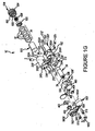
- Figure 1G shows an alternate embodiment of the invention, device 10'.
- the preferred embodiment of device 10' is preferably identical in all respects to device 10 except that it includes a modified housing 200' with a modified mechanical sight, a modified LSAA 300', an insulating sleeve 610 and a biasing collar 620. Only the features that are different from those already described with respect to device 10 shall be described in detail.
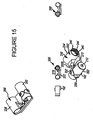
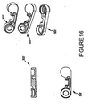
- Housing 200' (which is also shown in Figure 15 ) is preferably made of MIM stainless steel, but could be made of any suitable material, such as any suitable metal (for example, MIM carbon steel or extruded aluminum) or plastic.
- Housing 200' has a first end 200A', a second end 200B' and includes a first canister 202' and a second canister 230'.
- First canister 202' is configured to receive and retain the light source 20, which as shown is first positioned in light source adjustment apparatus 300', and then apparatus 300', with light source 20 inside, is positioned and retained in canister 202'.
- canister 202' has an outer surface 204', a first projection 206', a second projection 208', an inner cavity 210' in which apparatus 300' and light source 20 are retained, and an opening 212' through which the light source 20 can emit light.
- Canister 202' also includes an aperture 206A' that extends through projection 206' to inner cavity 210' and an aperture 208A' that extends through projection 208' to inner cavity 210'.
- Each of apertures 206A' and 208A' are configured to receive a moveable screw or screw 225 (previously described).
- the purpose of projection 206' and projection 208' (each of which project outward .075") are to provide additional area to support set screws 225. Other structures may be used for this purpose or no such structure may be used.
- Second canister 230' as shown is spaced apart from first canister 202' and is configured to receive and retain the power source 30.
- Canister 230' as shown has an outer surface 234', an inner cavity 240', a first end 242' and a second end 244'.
- Second end 244' is configured to open in order to add or change power source 30.
- second end 244' includes internal threads (shown in Figure 15 ) that mate with threads on power source retention cap 600 to allow cap 600 to be screwed onto end 244' and screwed off of end 244' in order to add or remove power source 30 from canister 230'.
- Housing 200' also includes a connective portion 270' that connects first canister 202' and second canister 230'.
- Connective portion 270' has a bottom surface 272' and a mount 102' attached to or integrally formed with bottom surface 272'.
- Mount 102' is for mechanically attaching device 10 to a gun and any suitable structure or structures may be used for this purpose.
- mount 274' is a generally a rail configured to be received in the slot (which may have a dovetail shape) formed on a gun.
- An aperture 273' (shown in Figure 15 ) may be formed in housing 200', in connective portion 270'.
- a set screw 2 is received in the aperture 273' and tightened so that it creates a pressure fit against a surface (preferably the base of a slot) of the gun to assist in retaining the device on the gun.
- An opening 200S' is formed in housing 200' to create a mechanical sight that, in this embodiment, forms the rear, mechanical sight for a gun to which device 10' is mounted.
- the rear mechanical sight is visually aligned with the front mechanical sight to properly sight a gun.
- a gun using device 10' can be sighted using light source 20, which is preferably a visible light laser.
- LSAA 300' The purpose of LSAA 300' is the same as for previously described LSAA 300 and any suitable structure may be utilized.
- LSAA 300' has a first collar 312 and a second collar 314, and this structure of the LSAA may be used with any suitable structure of a device according to the invention, including device 10, device 10', device 1000 or device 2000.
- First collar 312 as shown is tubular with an annular wall 316, passage 318, and it receives first end 20A of light source 20 in passage 318.
- Second collar 314 has an outer wall 320, a passage 322 and receives second end 20B of light source 20 in passage 322.
- Second collar 314 also includes a projection 314A on one side to bias light source 20 to a particular position in chamber 210.
- Each collar 312 and 314 is preferably comprised of elastomeric material, such as neoprene rubber of about 60 Shore A, to absorb shock, but either can be made of any suitable material.
- LSAA 300' is shaped to be biased towards apertures 250A and 252A.
- the position of light source 20 can be adjusted by tightening or loosening set screws 225 (previously described). For example, as one or both set screws 225 are tightened, the set screw(s) pushes against light source 20 and moves it either to the side and/or downward (in this embodiment) thereby adjusting the position of light source 20 within cavity 210'.
- Backing 500' is preferably stainless steel, but could be made of any suitable material, and its purpose is to hold integrated circuit board 400 to housing 200' and to protect integrated circuit board 400 and the other components inside of housing 200'.
- Backing 500' has a first side 500A' configured to fit over canister 202' at end 200B' and a second side 500B' configured to fit over end 242' of canister 230'. It further includes an opening 502' through which button 450 projects so it can be pressed by a user to turn light source 20 on and off, and openings 506' that align with screw holes 406 and screw retainers 250'. Screws 510 are then received through openings 506' and screw holes 406, and are threaded into retainers 250 to hold device 10 together.
- Backing 510' further includes an indentation 520' configured to receive a sighting insert 1022 (described in more detail below) to assist in mechanical sighting.
- Power source retention cap 600 has been previously described.
- Device 10' also includes an insulating sleeve 610 (which may be used with other embodiments of the invention, such as device 10, device 1000 or device 2000) formed of a suitable material, such as MYLAR, to prevent power source 30 from grounding to the inner wall of cavity 240.
- an insulating sleeve 610 (which may be used with other embodiments of the invention, such as device 10, device 1000 or device 2000) formed of a suitable material, such as MYLAR, to prevent power source 30 from grounding to the inner wall of cavity 240.
- a biasing collar 620 has an annular wall 622, a lip 624 and an opening 626 therethrough. Biasing collar 620 fits into cavity 606 of cap 600.
- Spring 608' which has a slightly different configuration but the same function as previously described spring 608, is received within opening 626. Biasing collar 600 assists in holding power source 30 in place during movement of device 10' and helps to prevent device 10' from turning on or off without a user intending to do so.
- Biasing collar 620 may be used with other embodiments of the invention, such as with device 10, device 1000 or device 2000, and is preferably comprised of 60 Shore A neoprene rubber although any suitable material may be used.
- a sighting device may be mounted to a gun in any suitable manner utilizing any suitable structure, and may be formed in an L-shape, T-shape or a U-shape.
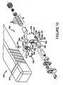
- Figures 12 and 13 show a device 1000 not according to the invention wherein the light source may be positioned on a side surface of a gun by, in this embodiment, forming device 1000 in an L-shaped or T-shaped configuration.
- Device 1000 is basically L-shaped and has a first leg 1002 and a second leg 1004.
- First leg 1002 is shown as being integrally formed with second leg 1004, but could be attached to second leg 1004 in any suitable manner.
- First leg portion 1002 in this embodiment, includes a mechanical sight portion 1002A, a base 1006 (which functions as a mount to attached to the slot of a gun), a top 1008, a first side 1010 and a second side 1012.
- base 1006 is configured to fit into a slot on a gun (as shown in Figure 13 , not forming part of the invention), but device 1000 can have any structure on first leg portion 1002 and/or second leg portion 1004 capable of attaching to a gun.
- Mechanical sight portion 1002A in first leg 1002 includes an opening 1014.
- An aperture 1016 passes through base 1006.
- a set screw 1018 which as shown is a socket head set screw, is threadingly received in aperture 1016 when first leg portion 1002 is positioned in a slot (such as slot 2010 shown in Figure 13 , not forming part of the invention), and set screw 1018 is tightened until it presses against the surface of the slot to assist in retaining device 1000 to the gun.
- First side 1010 includes an indentation 1020 that receives a sighting insert 1022 to assist in mechanically sighting the gun when device 1000 is mounted on the gun.
- Sighting insert 1022 may be pressure fit, snap fit and/or glued into indentation 1020, or attached to device 1000 in any suitable fashion.
- Other devices or structures applied to or formed as part of first leg 1002 could alternatively be used to assist in mechanical sighting, or no mechanical sight may be included.
- Sighting insert 1022 or any other mechanical sighting device could be luminescent (meaning it glows in the dark) and/or of any color, and white is one preferred color.
- the device could be the same color as the front mechanical sight (not shown) on the gun to assist the user in aligning the rear mechanical sight and front mechanical sight when aiming the gun.
- Second leg 1004 as shown includes a housing 1030.
- Housing 1030 has an outer wall 1032 and an inner dividing wall 1034 that divides structure 1030 into two chambers 1036 and 1038.
- Housing 1030 is preferably made of metal injection molded steel, but could be made of any suitable material, such as any suitable metal or plastic, including extruded aluminum.
- Chamber 1036 is for retaining a light source 20 (which was previously described and is preferably a laser) and chamber 1038 is for retaining a power source 30 (which was previously described and is preferably a plurality of batteries 32).
- housing 1030 has an outer surface 1032, a first projection 1036B and a second projection 1036C.
- An aperture 1036A passes through first projection 1036B and into cavity 1036 and a second aperture (not shown) passes through second projection 1036C and into cavity 1036.
- Each of these apertures is for receiving a set screw 225 (previously described).
- the purpose of projection 1036B and 1036C (each of which extend about .075" (1.905 cm) outward from outer surface 1032) is to provide additional thickness to support set screws 225. Other structures may be used for this purpose or no such structure may be used.
- a light source adjustment apparatus (or "LSAA”) 300 or 300' is preferably used in this embodiment and has the same function and a preferred structure as previously described with respect to device 10 or device 10'.
- Integrated circuit board 400A is configured to be received and mounted on second end 1030A of housing 1030.
- the purpose and function of board 400A is the same as previously described circuit board 400, and any suitable structure or device can be used for this purpose.
- Board 400A is preferably fiberglass and includes a push button switch 402A, an integrated circuit 404A and two through screw holes 406A.
- a button 450A is preferably plastic and of any suitable shape to fit with push button switch 402A and backing 500A, described below. Button 450A is for enabling a user to selectively activate switch 402A thus turning the light source 20 off and on, and any suitable device or structure can be used for this purpose.
- Backing 500A is preferably plastic or metal and its purpose is to hold integrated circuit board 400A to housing 1036 and to protect integrated circuit board 400A and the other components inside of housing 1036.
- Backing 500A has a first side 502A configured to fit over housing 1036 at end 1036A.
- Backing 500A further includes an opening 504A through which button 450A projects so it can be pressed by a user to turn light source 20 on and off, and openings 506A that align with screw holes 406A and screw retainers 250A. Screws 510A are then received through openings 506A and screw holes 406A, and are threaded into screw retainers 250A to hold device 1000 together.
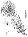
- Figure 14 shows a device 2000 not according to the invention that includes two light sources.
- Each light source could be of any type, such as a visible laser, an LED flashlight, an infra-red LED, or an infra-red laser. Any combination is possible and each light source may emit the same type of light or may emit different types of light.
- one light could be a visible laser and one could be an LED flashlight, or both could be visible lasers, or one could be an infra-red laser and the other could be an infra-red LED.
- each of the respective light sources may be operated independently of one another or may both be simultaneously operated.
- an LED flashlight and visible laser may simultaneously be operated to enable a user to simultaneously see in a dark area and sight the gun.
- the two light sources are side by side and device 2000 is configured to be on the top surface of a gun.
- one light source could be above the other (similar to the configuration of the light source and power source shown for device 1000 in Figures 12 and 13 , not forming part of the invention), or one light source could be on the top surface of the gun and another on a side surface.
- Housing 2200 is preferably made of MIM stainless steel, but could be made of any suitable material, such as any suitable metal (for example, MIM carbon steel or extruded aluminum) or plastic.
- Housing 2200 has a first end 2200A, a second end 2200B and includes a first canister 2202 and a second canister 2230.
- First canister 2202 is configured to receive and retain the light source 2020, which as shown is first positioned in light source adjustment apparatus 300' (which was previously described), and then LSAA 300', with light source 2020 inside, is positioned and retained in canister 2202.
- canister 2202 has an outer surface 2204, a first projection 2206, a second projection 2208, an inner cavity 2210 in which LSAA 300' and light source 2020 are retained, and an opening 2212 through which the light source 20 can emit light.
- Canister 2202 also includes an aperture 2206A that extends through projection 2206 to inner cavity 2210 and an aperture 2208A that extends through projection 2208 to inner cavity 2210.
- Each of apertures 2206A and 2208A are configured to receive a moveable screw or screw 225 (previously described).
- the purpose of projection 2206 and projection 2208 (each of which project outward about .075" (1.905 cm)) are to provide additional area to support set screws 225. Other structures may be used for this purpose or no such structure may be used.
- Second canister 2230 as shown is spaced apart from first canister 2202 and is configured to receive and retain second light source 2050.
- Canister 2230 as shown has an outer surface 2234, an inner cavity 2240, a first end 2242 and a second end 2244 through which light source 2050 can emit light.
- Second canister 2230 is configured to receive and retain the light source 2050, which as shown is first positioned in light source adjustment apparatus 300' (which was previously described), and then LSAA 300', with light source 2050 inside, is positioned and retained in canister 2230.
- Canister 2230 also includes an aperture 2236A that extends through projection 2236 to inner cavity 2240 and an aperture 2238A that extends through projection 2238 to inner cavity 2240.
- Each of apertures 2236A and 2208A are configured to receive a moveable set screw or screw 225 (previously described).
- the purpose and preferred configuration of each projection 2236 and 2238 are the same as for projections 2206 and 2208. Other structures may be used for this purpose or no structure may be used.
- Housing 2200 also includes a connective portion 2270 that connects first canister 2202 and second canister 2230.
- Connective portion 2270 has a bottom surface 2272 and a mount 2102 attached to or integrally formed with bottom surface 272.
- Mount 2102 is for mechanically attaching device 2000 to a gun and any suitable structure or structures may be used for this purpose.
- mount 2274 is a generally a rail configured to be received in the slot (which may have a dovetail shape) formed on a gun.
- An aperture (not shown) may be formed in housing 2200, in connective portion 2270.
- a set screw 2 is received in the aperture and tightened so that it creates a pressure fit against a surface (preferably the base of a slot) of the gun to assist in retaining the device on the gun.
- An opening 2200S is formed in housing 2200 to create a mechanical sight that, in this embodiment, forms the rear, mechanical sight for a gun to which device 2000 is mounted.
- the rear mechanical sight is visually aligned with the front mechanical sight to properly sight a gun.
- a gun using device 2000 can be sighted using light source 2020 and/or light source 2050, at least one of which is preferably a laser.
- Power Source 30 is a single 3V lithium coin cell battery.
- power source 30 could be of any suitable type and be positioned in any suitable location to power each of the light sources and the power source may include different batteries connected to different ones of the light sources.
- Integrated circuit board 400A is configured to be received and mounted on second end 2200 of housing 2200.
- the purpose and function of board 400A is the same as previously described circuit board 400, except that integrated circuit 404' can be used to turn on either the first light source, the second light source, or both of the light sources at the same time, and any suitable structure or device can be used for this purpose.
- Board 400A is preferably fiberglass and includes a push button switch 402A, and two through screw holes 406A.
- a button 450 (previously described) is preferably plastic and of any suitable shape to fit with push button switch 402 (previously described) and backing 500A, described below. Button 450 selectively activates switch 402 thus turning the light source 2020 and/or 2050 off and on, and any suitable device or structure can be used for this purpose.
- Backing 500' is preferably stainless steel, but could be of any suitable material, and its purpose is to hold integrated circuit board 400A to housing 2200 and to protect integrated circuit board 400A and the other components inside of housing 2200.
- Backing 500' has the same preferred structure as previously described and preferably includes sighting insert 1022. Screws 510A are received through openings 506' and screw holes 406A, and are threaded into retainers 2250 to hold device 2000 together.
- a preferred gun 2000 is a semi-automatic pistol, although a sighting device according to the invention can be used on any gun having the proper configuration for the sighting device to be mounted thereon.
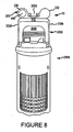
- Figures 3-6 , 8-11 and 13 show one preferred embodiment of a gun with which a device according to the invention can be used.
- Gun 2000 as shown is a Glock 17 pistol although a sighting device according to the invention may be used with any gun on which it can be properly mounted.
- a device according to the invention is preferably used with a semi-automatic pistol such as a Glock 17, 19, 21 or 23.
- Gun 2000 includes a slide 2002, a top surface 2004 (which as shown slide 2002), a rear surface 2006, two side surfaces 2008, a slot 2010 and a handle or grip 2012.
- Slot 2010 preferably has a dovetail shape. As shown, slot 2010 is formed in the top surface of gun 2000, near rear surface 2006, and preferably within 2" of rear surface 2006.
- a device according to the invention as shown is mounted by pressure fitting the mount (such as mount 102) into slot 2010.
- the gun such as gun 2000
- the gun is provided with two mechanical sights: one on the top surface near the front of the gun barrel (called the front sight), and another on the top surface near the rear surface (called the rear sight).
- the rear mechanical sight is often mounted in a slot, such as slot 2010, and it must first be removed in order to mount a device according to the invention in the slot, if the device is mounted in the slot.
Landscapes
- Engineering & Computer Science (AREA)
- General Engineering & Computer Science (AREA)
- Physics & Mathematics (AREA)
- Optics & Photonics (AREA)
- Telescopes (AREA)
- Aiming, Guidance, Guns With A Light Source, Armor, Camouflage, And Targets (AREA)
- Non-Portable Lighting Devices Or Systems Thereof (AREA)
- Toys (AREA)
Claims (18)
- Zielvorrichtung (10, 10') für den Einsatz mit einer Feuerwaffe, wobei diese Zielvorrichtung (10, 10') einen Laser, eine an den Laser anschließbare Energiequelle (30), ein hinteres mechanisches Visier (200S, 200S') und ein Gehäuse (200, 200') aufweist, welches eine Aufnahmevorrichtung (102, 102') enthält, die eine Bodenschiene ist, welche in ein an der Feuerwaffe ausgebildetes Langloch passt, wobei die Energiequelle (30) sich in einem gewissen Abstand vom Laser befindet, das hintere mechanische Visier (200S, 200S') zwischen dem Laser und der Energiequelle (30) angeordnet ist und die Aufnahmevorrichtung (102, 102') unterhalb des Lasers, der Energiequelle (30) und dem hinteren mechanischen Visier (200S, 200S') angeordnet ist, wobei das hintere mechanische Visier (200S, 200S') durch eine Öffnung in dem Gehäuse gebildet wird und dieses hintere mechanische Visier (200S, 200S') visuell mit dem vorderen mechanischen Visier der Feuerwaffe ausgerichtet ist, um mit der Feuerwaffe einwandfrei zielen zu können.
- Zielvorrichtung (10, 10') nach Anspruch 1, welche eine Höhe von nicht mehr als3/4" (1,905 cm) von der Oberfläche;1/2" (1,27 cm) von der Oberfläche oder3/8" (0,9525 cm) von der Oberfläche
aufweist. - Zielvorrichtung (10, 10') nach Anspruch 1, welche nicht größer ist als3" (7,62 cm) in der Länge;2" (5,08 cm) in der Länge;1 1/2" (3,81 cm) in der Länge oder0,9" (2,286 cm) in der Länge.
- Zielvorrichtung (10, 10') nach Anspruch 1, bei welcher die Energiequelle (30) durch eine oder mehrere Batterien gebildet wird und vorzugsweise diese Energiequelle (30) aus einer gewissen Anzahl von Silberoxidbatterien mit 1 - 3 V besteht, wobei stärker vorzuziehen ist, dass die Energiequelle aus vier Silberoxidbatterien zwischen 1 - 3 V gebildet wird.
- Zielvorrichtung (10, 10') nach Anspruch 1, welche außerdem eine Lichtquellen-Einstellapparatur zum Einstellen der Position des Lasers enthält.
- Zielvorrichtung (10, 10') nach Anspruch 5, bei welcher die Lichtquellen-Einstellapparatur (300, 300') einen inneren Hohlraum aufweist, der zumindest zum Teil den Laser aufnimmt, die Lichtquellen-Einstellapparatur (300, 300') vorzugsweise eine konische Gestalt aufweist oder die Lichtquellen-Einstellapparatur (300, 300') dadurch bewegt wird, dass eine oder mehrere Schrauben verstellt wird, wodurch die Position des Lasers eingestellt wird.
- Zielvorrichtung (10, 10') nach Anspruch 1, bei welcher
die Aufnahmevorrichtung (102, 102') dergestalt konfiguriert ist, dass sie in das Langloch durch Presspassung eingesetzt ist, oder
die Energiequelle (30) sich in einem gewissen Abstand vom Laser befindet. - Zielvorrichtung (10, 10') nach Anspruch 1, welche ein Gehäuse (200, 200') enthält, wobei dieses Gehäuse (200, 200') einen ersten Behälter zwecks Aufnahme des Lasers und einen zweiten Behälter zwecks Aufnahme der Energiequelle (30) enthält, wobei vorzugsweise zumindest ein Teil des Gehäuses (200, 200') aus Metall besteht, wobei stärker vorzuziehen ist, dass zumindest ein Teil des Gehäuses aus Aluminium besteht.
- Zielvorrichtung (10, 10') nach Anspruch 1, welche ein Gehäuse (200, 200') enthält, wobei dieses Gehäuse (200, 200') einen ersten Behälter zwecks Aufnahme des Lasers und einen zweiten Behälter zwecks Aufnahme der Energiequelle (30) enthält, wobei zumindest ein Teil des Gehäuses (200, 200') aus Stahl besteht und vorzugsweise mindestens ein Teil des Gehäuses (200, 200') aus rostfreiem Stahl oder aus Maschinenspritzgussstahl besteht.
- Zielvorrichtung (10, 10') nach Anspruch 1, welche ein Gehäuse (200, 200') enthält, wobei dieses Gehäuse (200, 200') einen ersten Behälter (2202) zwecks Aufnahme des Lasers und einen zweiten Behälter (2230) zwecks Aufnahme der Energiequelle (30) enthält, wobei das Gehäuse (200, 200') einen verbindenden Bereich zwischen dem ersten Behälter (2202) und dem zweiten Behälter (2230) enthält und die Aufnahmevorrichtung (102, 102') vorzugsweise in dem verbindenden Bereich enthalten ist oder der verbindende Bereich das mechanische Visier enthält, wobei stärker vorzuziehen ist, dass das mechanische Visier zwischen dem ersten Behälter (2202) und dem zweiten Behälter (2230) angeordnet ist.
- Zielvorrichtung (10, 10') nach Anspruch 1, welche außerdem eine Öffnung zwecks Aufnahme einer Stellschraube enthält und diese Öffnung durch die Aufnahmevorrichtung (102, 102') hindurch ausgebildet ist und dergestalt konfiguriert ist, dass die Stellschraube durch die Aufnahmevorrichtung (102, 102') hindurch führen kann und Druck auf das Langloch ausüben kann, um bei der Fixierung der Zielvorrichtung an der Feuerwaffe dienlich zu sein.
- Zielvorrichtung (10, 10') nach Anspruch 1, bei welcher der Laser im Pulsbetrieb arbeitet, wenn er Licht emittiert, wobei der Laser vorzugsweise mit 1000 Pulsen pro Sekunde arbeitet, wenn er Licht emittiert, wobei stärker vorzuziehen ist, dass der Laser beim Pulsen ein Tastverhältnis von 50 % hat.
- Zielvorrichtung (10, 10') nach Anspruch 1, bei welcher der Laser- weniger als 10 Milliampere Strom zieht, wenn er Licht emittiert, oder- 6 - 8 Milliampere Strom zieht, wenn er Licht emittiert.
- Zielvorrichtung (10, 10') nach Anspruch 1, welche an ein Langloch auf der Oberseite der Feuerwaffe montierbar ist, wobei dieses Langloch innerhalb von 2" (5,08 cm) von der Rückfläche liegt; vorzugsweise das Langloch die Gestalt eines Schwalbenschwanzes aufweist; der Laser an eine Fläche der Feuerwaffe montiert ist und sich nicht weiter als 3/4" (1,905 cm) von der Fläche, an die er montiert ist, nach außen erstreckt, oder der Laser an eine Fläche der Feuerwaffe montiert ist und sich nicht weiter als 3/8" (0,9525 cm) von der Fläche, an die er montiert ist, nach außen erstreckt.
- Zielvorrichtung (10, 10') nach Anspruch 1, bei welcher das mechanische Visier (200, 200') einen Visiereinsatz enthält, wobei dieser Visiereinsatz vorzugsweise lumineszent ist.
- Vorrichtung (10, 10') nach Anspruch 1, welche außerdem eine sekundäre Lichtquelle aufweist, wobei vorzugsweise- diese sekundäre Lichtquelle einen gewissen Abstand vom Laser hat oder- ein mechanisches Visier zwischen dem Laser und der sekundären Quelle vorhanden ist.
- Vorrichtung (10, 10') nach Anspruch 1, welche außerdem eine sekundäre Lichtquelle aufweist, wobei- jeder von beiden, Laser und sekundäre Lichtquelle, an die Energiequelle (30) angeschlossen werden kann oder- der Laser und die sekundäre Lichtquelle gleichzeitig Licht aussenden können.
- Vorrichtung (10, 10') nach Anspruch 17, bei welcher die sekundäre Lichtquelle- ein Infrarotlicht ist;- eine Blinkleuchte, vorzugsweise eine LED-Blinkleuchte ist oder- ein Laser im sichtbaren Bereich oder ein Infrarotlaser ist.
Applications Claiming Priority (2)
| Application Number | Priority Date | Filing Date | Title |
|---|---|---|---|
| US9476508P | 2008-09-05 | 2008-09-05 | |
| US12/249,781 US8627591B2 (en) | 2008-09-05 | 2008-10-10 | Slot-mounted sighting device |
Publications (3)
| Publication Number | Publication Date |
|---|---|
| EP2208960A2 EP2208960A2 (de) | 2010-07-21 |
| EP2208960A3 EP2208960A3 (de) | 2010-09-22 |
| EP2208960B1 true EP2208960B1 (de) | 2014-03-19 |
Family
ID=42212090
Family Applications (1)
| Application Number | Title | Priority Date | Filing Date |
|---|---|---|---|
| EP09169476.0A Active EP2208960B1 (de) | 2008-09-05 | 2009-09-04 | Langloch-montierte Zielvorrichtung |
Country Status (2)
| Country | Link |
|---|---|
| US (1) | US8627591B2 (de) |
| EP (1) | EP2208960B1 (de) |
Families Citing this family (34)
| Publication number | Priority date | Publication date | Assignee | Title |
|---|---|---|---|---|
| US8627591B2 (en) | 2008-09-05 | 2014-01-14 | Larry Moore | Slot-mounted sighting device |
| US8312665B2 (en) | 2008-10-10 | 2012-11-20 | P&L Industries, Inc. | Side-mounted lighting device |
| US8607495B2 (en) * | 2008-10-10 | 2013-12-17 | Larry E. Moore | Light-assisted sighting devices |
| US9170079B2 (en) | 2011-01-18 | 2015-10-27 | Larry E. Moore | Laser trainer cartridge |
| US8832983B1 (en) * | 2011-09-16 | 2014-09-16 | Alec Daniel Wolf | Firearm with interchangeable calibers and/or improved sights |
| US10532275B2 (en) | 2012-01-18 | 2020-01-14 | Crimson Trace Corporation | Laser activated moving target |
| US8844189B2 (en) | 2012-12-06 | 2014-09-30 | P&L Industries, Inc. | Sighting device replicating shotgun pattern spread |
| US9297614B2 (en) | 2013-08-13 | 2016-03-29 | Larry E. Moore | Master module light source, retainer and kits |
| US9506726B2 (en) | 2013-12-09 | 2016-11-29 | ZEV Technologies, Inc. | Accessory mounting system for firearms |
| US9182194B2 (en) | 2014-02-17 | 2015-11-10 | Larry E. Moore | Front-grip lighting device |
| US9506723B2 (en) * | 2014-03-03 | 2016-11-29 | Wilcox Industries Corp. | Modular sighting assembly and method |
| US9644826B2 (en) | 2014-04-25 | 2017-05-09 | Larry E. Moore | Weapon with redirected lighting beam |
| US9829277B2 (en) * | 2014-07-28 | 2017-11-28 | ZEROlight LLC | Illumination system for weapon optics |
| US10436553B2 (en) | 2014-08-13 | 2019-10-08 | Crimson Trace Corporation | Master module light source and trainer |
| US10809037B2 (en) * | 2015-01-09 | 2020-10-20 | Hogue, Inc. | Firearm handgrip assembly with laser gunsight system |
| US10132595B2 (en) | 2015-03-20 | 2018-11-20 | Larry E. Moore | Cross-bow alignment sighter |
| US20170082399A1 (en) * | 2015-09-23 | 2017-03-23 | Larry E. Moore | Grip aiming device for weapons |
| US10753700B2 (en) | 2016-01-15 | 2020-08-25 | ZEV Technologies, Inc. | Firearm accessory mounting system |
| US9829280B1 (en) | 2016-05-26 | 2017-11-28 | Larry E. Moore | Laser activated moving target |
| US10837737B1 (en) * | 2016-08-02 | 2020-11-17 | Jimmie L. Wright | LED illuminating weapon sighting system |
| US10209030B2 (en) | 2016-08-31 | 2019-02-19 | Larry E. Moore | Gun grip |
| US10222171B2 (en) | 2016-12-01 | 2019-03-05 | Bushnell Inc. | Forward grip laser (FGL) |
| US10215530B1 (en) * | 2017-04-25 | 2019-02-26 | Anthony Watts | Laser firearm sight apparatus |
| US10436538B2 (en) | 2017-05-19 | 2019-10-08 | Crimson Trace Corporation | Automatic pistol slide with laser |
| USD860375S1 (en) | 2017-10-06 | 2019-09-17 | Bushnell Inc. | Forward grip laser sight |
| USD915541S1 (en) | 2017-10-06 | 2021-04-06 | Vista Outdoor Operations Llc | Forward grip laser sight |
| US10209033B1 (en) | 2018-01-30 | 2019-02-19 | Larry E. Moore | Light sighting and training device |
| USD894988S1 (en) | 2018-12-18 | 2020-09-01 | Crimson Trace Corporation | Scope |
| US12117267B2 (en) * | 2020-03-01 | 2024-10-15 | Zi Qing Shi | Detachable sight with momentary switch of light with control logic |
| US11460274B2 (en) | 2020-03-02 | 2022-10-04 | David J. Dawson, JR. | Sighting systems, components, and methods |
| US11365954B2 (en) * | 2020-07-06 | 2022-06-21 | Martin James Bordson | Firearm optic assembly |
| US12410988B1 (en) | 2024-03-07 | 2025-09-09 | Andrew DENT | Forearm grip for a firearm |
| US12638268B2 (en) | 2024-03-07 | 2026-05-26 | Andrew DENT | Extendable blade firearm attachment device |
| US20260098709A1 (en) * | 2024-10-03 | 2026-04-09 | WHG Properties, LLC | Modular scope mounts and accessory mounts |
Family Cites Families (298)
| Publication number | Priority date | Publication date | Assignee | Title |
|---|---|---|---|---|
| US1898566A (en) | 1931-12-16 | 1933-02-21 | Noel Albert | Device for applying subcaliber barrels to revolvers of the solid-frame swing-out cylinder type |
| FR862247A (fr) | 1939-08-16 | 1941-03-01 | Appareil de visée pour tir de nuit | |
| US2268056A (en) | 1940-08-21 | 1941-12-30 | Raymond T Moloney | Sight for guns |
| US2357951A (en) | 1941-08-19 | 1944-09-12 | Saint Cyr Corp | Pneumatic gun |
| US2430469A (en) | 1943-12-20 | 1947-11-11 | James C Karnes | Luminous gun sight |
| US2597565A (en) | 1949-11-12 | 1952-05-20 | Chandler | Flashlight attachment for guns |
| US2780882A (en) | 1953-11-16 | 1957-02-12 | Olin Mathieson | Electrically powered fire control mechanism for firearms |
| US2773309A (en) | 1955-06-27 | 1956-12-11 | Raymond St C Elliott | Bore sighting device for firearms |
| US2826848A (en) | 1955-08-26 | 1958-03-18 | Thomas E Davies | Hand hold for guns |
| US2904888A (en) | 1957-12-17 | 1959-09-22 | Casimer M Niesp | Gun sight |
| US3112567A (en) | 1962-02-16 | 1963-12-03 | George L Flanagan | Device for setting telescopic gunsights |
| US3192915A (en) | 1962-05-28 | 1965-07-06 | Kenneth S Norris | Apparatus for projecting animal food |
| US3284905A (en) | 1964-03-04 | 1966-11-15 | Ernest P Simmons | Sight for shotguns |
| US3510965A (en) | 1967-04-14 | 1970-05-12 | Don E Rhea | Training aid for sighting small arms |
| US3573868A (en) | 1967-11-13 | 1971-04-06 | Carlo Giannetti | Fiber optical target practice system |
| US3526972A (en) | 1968-03-18 | 1970-09-08 | Hans C Sumpf | Marksman's practicing device |
| US3641676A (en) | 1969-08-07 | 1972-02-15 | Nite Site Inc | Radioluminescent gunsight and method |
| US3645635A (en) | 1970-05-05 | 1972-02-29 | Weaver Co W R | Sighting device |
| US3801205A (en) | 1972-04-06 | 1974-04-02 | Pulfer Ag | Process and device for the survey alignment with a laser beam |
| US3914873A (en) | 1973-02-27 | 1975-10-28 | Jr John B Elliott | Illuminated gun sights |
| US3992783A (en) | 1975-03-27 | 1976-11-23 | Precision Tool & Machine Co. | Recoil resistant mounting system |
| US3995376A (en) | 1975-04-03 | 1976-12-07 | Cerberonics, Inc. | Small arms laser training device |
| US4079534A (en) | 1976-08-24 | 1978-03-21 | Snyder Wesley L | Sighting apparatus for firearms |
| CA1051702A (en) | 1976-10-20 | 1979-04-03 | Norman E. Lusk | Revolver-type repeating gun |
| US4305091B2 (en) | 1977-01-31 | 1998-02-10 | J Carl Cooper | Electronics noise reducing apparatus and method |
| US4222564A (en) | 1977-06-13 | 1980-09-16 | Aba Electromechanical Systems, Inc. | Automated scoring target system |
| US4148245A (en) | 1977-12-12 | 1979-04-10 | Btgco | Fluid propellant projectile firing device |
| US4295289A (en) | 1978-10-10 | 1981-10-20 | Snyder Wesley L | Laser aiming device with lateral shock absorber |
| US4233770A (en) * | 1978-10-23 | 1980-11-18 | Filippis Gerald De | Laser aiming device for weapons |
| US4220983A (en) * | 1978-12-18 | 1980-09-02 | Schroeder Gary P | Illuminated bowsight |
| US4234911A (en) | 1979-03-13 | 1980-11-18 | Faith Donald L | Optical firing adaptor |
| US4348828A (en) | 1979-09-24 | 1982-09-14 | Snyder Wesley L | Laser-aiming system with means for electrical arc suppression |
| US4481561A (en) | 1983-02-01 | 1984-11-06 | Site-Lite, Inc. | Gun bore sighting flashlight activated upon breech closure |
| US4488369A (en) | 1983-05-25 | 1984-12-18 | Todd Van Note | Marksmanship training apparatus |
| US4567810A (en) | 1984-03-13 | 1986-02-04 | Wildfire Munitions, Inc. | Automatic firearm |
| US4541191A (en) | 1984-04-06 | 1985-09-17 | Morris Ernest E | Weapon having a utilization recorder |
| ATE74201T1 (de) | 1986-01-18 | 1992-04-15 | Accles & Shelvoke Ltd | Vorrichtung zum uebungsschiessen. |
| US4763431A (en) | 1986-09-25 | 1988-08-16 | Allan Robert E | Handgun locking and unlocking apparatus |
| US4713889A (en) | 1986-11-14 | 1987-12-22 | Santiago Julio A | Illuminated gunsight |
| US4825258A (en) | 1988-01-04 | 1989-04-25 | Whitson John M | Device for bore alignment of gun sights |
| US5179124A (en) | 1988-01-25 | 1993-01-12 | University Of Iowa Research Foundation | Anti-inflammatory for use in external and internal eye inflammations |
| US4939320A (en) | 1988-03-01 | 1990-07-03 | Graulty Mark T | Self-setting switch-actuating assembly and method |
| US4878307A (en) | 1988-04-22 | 1989-11-07 | L&S Technologies, Inc. | Gunsight mounting device for a revolver |
| US4891476A (en) | 1988-05-09 | 1990-01-02 | Illinois Tool Works, Inc. | Index rotary switch |
| US4939863A (en) | 1988-08-31 | 1990-07-10 | Emerging Technologies, Inc. | Laser aiming device for firearms, archery bows, and crossbows |
| US4876816A (en) | 1988-11-18 | 1989-10-31 | Triplett Melvin W | Target illuminating aiming system |
| US4967642A (en) | 1989-02-14 | 1990-11-06 | Ion Mihaita | Machine gun |
| US4934086A (en) | 1989-03-31 | 1990-06-19 | Houde Walter William R | Recoil spring guide mounting for laser sight |
| US4953316A (en) | 1989-09-25 | 1990-09-04 | Litton Sr Ernest C | Choke storage device for shotguns |
| US5052138A (en) | 1989-12-01 | 1991-10-01 | Philip Crain | Ammunition supply indicating system |
| US5241146A (en) | 1989-12-28 | 1993-08-31 | Priesemuth W | Contact-type switch |
| US5001836A (en) | 1990-02-05 | 1991-03-26 | Camtronics, Inc. | Apparatus for boresighting a firearm |
| US5033219A (en) | 1990-02-06 | 1991-07-23 | Emerging Technologies, Inc. | Modular laser aiming system |
| US5090805A (en) | 1990-08-15 | 1992-02-25 | Blount, Inc. | Bow sight with projected reticle aiming spot |
| US5048215A (en) | 1990-08-30 | 1991-09-17 | Calico Light Weapon Systems | Front grip for a firearm |
| US5048211A (en) | 1990-11-01 | 1991-09-17 | Norbert Hepp | Safety lock for firearms |
| US5299375A (en) | 1991-01-24 | 1994-04-05 | Laser Devices, Inc. | Laser diode alignment mechanism |
| US5178265A (en) | 1991-02-04 | 1993-01-12 | White Consolidated Industries, Inc. | Push-push snap switch |
| US5228427A (en) | 1991-05-06 | 1993-07-20 | Smart Parts, Inc. | Improved barrel for paintball gun |
| US5179235A (en) | 1991-09-10 | 1993-01-12 | Toole Ronald L | Pistol sighting device |
| US5237773A (en) | 1991-09-20 | 1993-08-24 | Claridge Hi-Tec Inc. | Integral laser sight, switch for a gun |
| US5272514A (en) * | 1991-12-06 | 1993-12-21 | Litton Systems, Inc. | Modular day/night weapon aiming system |
| US5177309A (en) | 1991-12-23 | 1993-01-05 | Willoughby Brian D | Laser-aimed weapons system |
| US5581898A (en) | 1993-07-30 | 1996-12-10 | Laser Devices, Inc. | Modular sighting laser for a firearm |
| DE9204927U1 (de) | 1992-04-09 | 1992-07-23 | Jung, Theo, 5204 Lohmar | Vorrichtung zum Einrichten eines Visiers |
| US5365669A (en) | 1992-12-23 | 1994-11-22 | Rustick Joseph M | Laser boresight for the sighting in of a gun |
| US5373644A (en) * | 1992-11-24 | 1994-12-20 | Depaoli; Alfred C. | Reflex luminous dot sighting instrument with undesired dot light blocking |
| FR2698961B3 (fr) | 1992-12-03 | 1995-02-17 | Bhm Ste Civile Rech | Dispositif émetteur d'un faisceau laser apte à servir de niveau. |
| US5355609A (en) | 1992-12-04 | 1994-10-18 | Schenke Reynold A | Laser beam sighting apparatus with a selectively adjustable beam width |
| US5531040A (en) | 1993-01-14 | 1996-07-02 | Tac Star Industries, Inc. | Laser module mounting means for weapons and other applications |
| US5419072A (en) | 1993-01-14 | 1995-05-30 | Moore; Larry | Internal laser sight for weapons |
| US5392550A (en) | 1993-01-14 | 1995-02-28 | Moore; Larry | Internal laser sight for weapons |
| US5343376A (en) | 1993-03-11 | 1994-08-30 | Huang Chao C | Structure of laser pointer |
| US5355608A (en) | 1993-06-08 | 1994-10-18 | Teetzel James W | Concealed laser module sight apparatus |
| US5669174A (en) | 1993-06-08 | 1997-09-23 | Teetzel; James W. | Laser range finding apparatus |
| US5555662A (en) | 1993-06-08 | 1996-09-17 | Teetzel; James W. | Laser range finding apparatus |
| US5481819A (en) | 1993-06-08 | 1996-01-09 | Teetzel; James W. | Laser module apparatus |
| US5499455A (en) | 1993-07-15 | 1996-03-19 | Palmer; Michael R. | Portable reticle alignment device for firearms |
| US5435091A (en) | 1993-08-05 | 1995-07-25 | Crimson Trace Corp. | Handgun sighting device |
| US5367779A (en) | 1993-08-18 | 1994-11-29 | Cheng Long Plastic Co., Ltd. | Laser marker |
| US5375362A (en) | 1993-10-07 | 1994-12-27 | Sturm, Ruger & Company, Inc. | Laser sighted firearm |
| US5455397A (en) | 1993-12-21 | 1995-10-03 | Honeywell Inc. | Zero reference rotation sense indicator |
| NO178651C (no) | 1994-01-11 | 1996-05-08 | Trojan Aviat As | Optisk patron |
| US5454168A (en) | 1994-01-31 | 1995-10-03 | Langner; F. Richard | Bore sighting system and method |
| US5822905A (en) | 1994-02-23 | 1998-10-20 | Teetzel; James W. | Firearm hand grips for controlling an electronic module |
| US5488795A (en) | 1994-02-28 | 1996-02-06 | American Laser Technology, Inc. | Multi-caliber laser firing cartridge |
| US5432598A (en) | 1994-03-29 | 1995-07-11 | Szatkowski; David | Apparatus for laser assisted firearm sights alignment |
| US5446535A (en) | 1994-05-09 | 1995-08-29 | Williams; John H. | Firearm non-firing sight alignment system |
| USD368121S (en) | 1994-06-15 | 1996-03-19 | Chap Mei Plastic Toys Mfy. Ltd. | Toy gun |
| US5706600A (en) | 1994-07-08 | 1998-01-13 | Crimson Trace Corporation | Laser sighting device for a weapon |
| US5618099A (en) | 1994-07-29 | 1997-04-08 | Brubacher; Michael | Sighting device |
| US5598958A (en) | 1994-09-12 | 1997-02-04 | Ryan, Iii; Willis N. | Competition holsters |
| US5467552A (en) | 1994-10-12 | 1995-11-21 | Pachmayr Ltd. | Gun sight mounting structure |
| US5448834A (en) | 1994-12-09 | 1995-09-12 | Quarton Inc. | Telescope sight collimating device |
| US5621999A (en) | 1994-12-27 | 1997-04-22 | Tac Star Industries, Inc. | Externally mountable laser sight with slide switch |
| US5590486A (en) | 1994-12-27 | 1997-01-07 | Tac Star Industries, Inc. | Externally mountable laser sight for weapons and other applications |
| US5557872A (en) | 1995-05-25 | 1996-09-24 | Langner; F. Richard | Power supply for firearm accessories |
| US5685636A (en) | 1995-08-23 | 1997-11-11 | Science And Engineering Associates, Inc. | Eye safe laser security device |
| US5622000A (en) | 1995-09-11 | 1997-04-22 | Marlowe; Ira M. | Laser sighting system for firearm fore handgrip assembly |
| US6023875A (en) | 1995-10-16 | 2000-02-15 | Fell; Mark Kevin | Tactically advanced combat mount (TACM III ™) illuminating devices and illuminating mounting systems for firearms and other applications |
| US5671561A (en) * | 1995-11-14 | 1997-09-30 | Emerging Technologies, Inc. | Modular, combination laser and electronic aiming system |
| US5788500A (en) | 1995-12-04 | 1998-08-04 | Oerlikon-Contraves Ag | Continuous wave laser battlefield simulation system |
| US6035843A (en) | 1996-01-16 | 2000-03-14 | Smart Parts, Inc. | Pneumatically operated projectile launching device |
| US5967133A (en) | 1996-01-16 | 1999-10-19 | Smart Parts, Inc. | Pneumatically operated projectile launching device |
| US5694202A (en) | 1996-01-22 | 1997-12-02 | Hughes Aircraft Company | Universal boresight tool for small arms weapons |
| US5685106A (en) | 1996-02-29 | 1997-11-11 | Ortek Ltd. | Laser cartridge |
| US5735070A (en) | 1996-03-21 | 1998-04-07 | Vasquez; Eduardo C. | Illuminated gun sight and low ammunition warning assembly for firearms |
| US5704153A (en) | 1996-07-23 | 1998-01-06 | Colt's Manufacturing Company, Inc. | Firearm battery and control module |
| US6237271B1 (en) | 1996-07-23 | 2001-05-29 | Colt's Manufacturing Company, Inc. | Firearm with safety system having a communication package |
| US5842300A (en) | 1996-09-09 | 1998-12-01 | Fss, Inc. | Retrofittable laser and recoil system for a firearm |
| EP0929786B1 (de) | 1996-10-02 | 2003-02-12 | Kehl, Hermann | Laserpistole |
| US5694713A (en) | 1996-11-06 | 1997-12-09 | Paldino; Arthur | Handgun with internal laser sight having elevational adjustment mechanism |
| US5787631A (en) | 1996-12-09 | 1998-08-04 | Acu-Sight, Inc. | Laser bore sight |
| US5983774A (en) | 1997-03-07 | 1999-11-16 | Mihaita; Ion | Machine gun |
| US5892221A (en) | 1997-03-24 | 1999-04-06 | Lev; Shlomo | Combat simulation method and system utilizing lasers with wireless activation |
| US6318228B1 (en) | 1997-04-24 | 2001-11-20 | Ramtech 2000, L.L.C. | Forcible entry device |
| US5847345A (en) | 1997-08-11 | 1998-12-08 | Harrison; Charles V. | Push button electrical switch |
| US6151788A (en) | 1997-08-14 | 2000-11-28 | Cox; Stacey | Laser beam for sight alignment |
| JP2003526765A (ja) | 1997-08-25 | 2003-09-09 | ビームヒット,リミティド ライアビリティー カンパニー | ネットワークに接続されたレーザ標的式の火器訓練システム |
| US6568118B1 (en) | 1997-09-22 | 2003-05-27 | James W. Teetzel | Grenade launcher sighting assembly |
| US5905238A (en) | 1998-01-28 | 1999-05-18 | Hung; Wen-Hui | Electrical switch capable of emitting light |
| US6366349B1 (en) | 1998-05-18 | 2002-04-02 | Lasermax, Inc. | Apparatus for aligning optical elements in response to the display of a reflected reticle image and method of aligning |
| US20050257415A1 (en) | 1998-07-02 | 2005-11-24 | Solinsky Kenneth S | Auxiliary device for a weapon and attachment thereof |
| US6442880B1 (en) | 1998-07-31 | 2002-09-03 | Robert M. Allan | Firearm with locking and unlocking apparatus |
| US6003504A (en) | 1998-08-20 | 1999-12-21 | Npf Limited | Paint ball gun |
| US6345464B1 (en) * | 1999-01-13 | 2002-02-12 | Surefire, Llc | Firearms with target illuminators, electric switching devices and battery power sources |
| US6219952B1 (en) | 1999-01-25 | 2001-04-24 | Jonathan E. Mossberg | Magnetic tag firearm safety enhancement system |
| DE29906940U1 (de) | 1999-04-17 | 1999-10-21 | Oerlikon Contraves GmbH, 78333 Stockach | Feuerwaffe, insbesondere Handfeuerwaffe |
| US6742299B2 (en) | 1999-05-24 | 2004-06-01 | Strandstar Instruments, L.L.C. | Laser device for use in adjusting a firearm's sight |
| US6230431B1 (en) | 1999-07-07 | 2001-05-15 | Limate Corporation | Night laser sight |
| GB9916676D0 (en) | 1999-07-15 | 1999-09-15 | Scient Generics Ltd | Effiecient optical source for weapon sights |
| US6371004B1 (en) | 1999-08-12 | 2002-04-16 | Stoney Point Products, Inc. | Laser beam apparatus for adjusting telescopic gun sights |
| US6434874B1 (en) | 1999-12-14 | 2002-08-20 | Stephen Charles Hines | Digit support |
| US6606797B1 (en) | 1999-12-17 | 2003-08-19 | Roger A. Gandy | Laser sighting device |
| US6301046B1 (en) | 1999-12-31 | 2001-10-09 | Jds Uniphase Corporation | Interleaver/deinterleavers causing little or no dispersion of optical signals |
| US6389729B2 (en) | 2000-01-04 | 2002-05-21 | R. Walter Rauch | Device for storing and transporting firearm disassembly tools within hand grip |
| WO2001055664A2 (en) | 2000-01-13 | 2001-08-02 | Beamhit, Llc | Laser transmitter assembly configured for placement within a firing chamber and method of simulating firearm operation |
| EP1255960A2 (de) | 2000-01-13 | 2002-11-13 | Beamhit, LLC | Übungssystem mit einer laserfeuerwaffe und verfahren zum simulieren der wirkung einer feuerwaffe mittels einer platzpatrone |
| US6363648B1 (en) | 2000-01-27 | 2002-04-02 | William H. Grube | Laser aiming light for firearms |
| US6295753B1 (en) | 2000-02-15 | 2001-10-02 | Laser Devices, Inc. | Laser precision bore sight assembly |
| US6289624B1 (en) | 2000-02-22 | 2001-09-18 | Hughes Product Company, Inc. | Laser bore sight device and method |
| US6397509B1 (en) | 2000-03-23 | 2002-06-04 | F. Richard Langner | Bore sighting apparatus |
| US6389730B1 (en) | 2000-05-19 | 2002-05-21 | Marlo D. Millard | Firearm sighting aid device |
| US6575753B2 (en) | 2000-05-19 | 2003-06-10 | Beamhit, Llc | Firearm laser training system and method employing an actuable target assembly |
| DE60115445T2 (de) | 2000-06-09 | 2006-09-07 | L-3 Communications Corporation | Feuerwaffenlaserübungssystem und -verfahren zur feuerwaffenübungserleichterung mit verschiedenen zielen und visueller rückkopplung simulierter geschossaufschlagsorten |
| US6430861B1 (en) | 2000-06-12 | 2002-08-13 | Tyler Ayers | Electronically controlled firearm |
| US6406298B1 (en) | 2000-06-19 | 2002-06-18 | Cubic Defense Systems, Inc. | Low cost laser small arms transmitter and method of aligning the same |
| US6650669B1 (en) | 2000-07-24 | 2003-11-18 | Daniel K. Adkins | Laser activation circuit for crossbows |
| US6385893B1 (en) | 2000-08-08 | 2002-05-14 | Chung-Tien Cheng | Mounting device of pistol laser sight |
| US6631668B1 (en) | 2000-11-10 | 2003-10-14 | David Wilson | Recoilless impact device |
| US20020073561A1 (en) | 2000-12-15 | 2002-06-20 | Ying Chou Liao | Laser level |
| US6631580B2 (en) | 2001-03-13 | 2003-10-14 | Hunts, Inc. | Firearm bore sight system |
| US6487807B1 (en) | 2001-03-16 | 2002-12-03 | Matt Kopman | Tripod gun handle |
| US6591536B2 (en) | 2001-06-07 | 2003-07-15 | Lasermax Inc. | Method and apparatus for side of frame positioning of laser sights and LED illuminators |
| WO2002101318A2 (en) | 2001-06-08 | 2002-12-19 | Beamhit, Llc | Firearm laser training system and method facilitating firearm training for extended range targets with feedback of firearm control |
| US6499247B1 (en) | 2001-07-27 | 2002-12-31 | Stoney Point Products, Inc. | Laser bore-sight scope and mount for riffles |
| US6526688B1 (en) | 2001-08-13 | 2003-03-04 | Lewis Danielson | Apparatus and method for actuating a weapon accessory by a laser sighting beam |
| US20030180692A1 (en) | 2002-03-22 | 2003-09-25 | Skala James A. | Continuous aimpoint tracking system |
| ITMI20020855A1 (it) | 2002-04-22 | 2003-10-22 | Beretta Armi Spa | Calcio per arma da fuoco |
| US6886287B1 (en) | 2002-05-18 | 2005-05-03 | John Curtis Bell | Scope adjustment method and apparatus |
| US7624528B1 (en) | 2002-05-18 | 2009-12-01 | John Curtis Bell | Scope adjustment method and apparatus |
| US8468930B1 (en) | 2002-05-18 | 2013-06-25 | John Curtis Bell | Scope adjustment method and apparatus |
| AT7134U1 (de) | 2002-05-28 | 2004-10-25 | Gen Headquarters Of The Armed | Visiereinrichtung für pistolen |
| US6931775B2 (en) | 2002-06-05 | 2005-08-23 | Lockheed Martin Corporation | Remote control module for a vehicle |
| US6622414B1 (en) | 2002-06-18 | 2003-09-23 | Keith Oliver | Bore sight |
| US6671991B1 (en) | 2002-07-03 | 2004-01-06 | Lewis A. Danielson | Target illuminator for long gun |
| US6782789B2 (en) | 2002-09-09 | 2004-08-31 | Mcnulty, Jr. James F. | Electric discharge weapon for use as forend grip of rifles |
| USD487791S1 (en) | 2002-09-18 | 2004-03-23 | Robert Freed | Magazine surround |
| US6854205B2 (en) | 2002-12-09 | 2005-02-15 | Timothy Carver Wikle | Grip and firearm with grip having internal inwardly stepped battery storage chamber |
| US7303306B2 (en) | 2003-02-10 | 2007-12-04 | First-Light Usa, Llc | Multi-purpose flashlight device and method of using same |
| DE10310802A1 (de) | 2003-03-12 | 2004-09-23 | Heckler & Koch Gmbh | Handfeuerwaffe und Handgriff für diese |
| EP1623181A2 (de) | 2003-04-07 | 2006-02-08 | Insight Technology Incorporated | Drahtlos gesteuerte vorrichtungen für eine waffe und drahtlose steuerung davon |
| US7331137B2 (en) | 2003-07-03 | 2008-02-19 | Yao-Hsi Hsu | Laser pointer as auxiliary sight of firearm |
| WO2005017439A2 (en) | 2003-08-05 | 2005-02-24 | R/M Equipment, Inc. | Weapon grip assembly |
| US7454858B2 (en) | 2003-08-05 | 2008-11-25 | R/M Equipment, Inc. | Weapon grip assembly |
| US7069661B2 (en) | 2003-08-29 | 2006-07-04 | Wen Hsin Liao | Laser leveling device having selectable light beam |
| US7049575B2 (en) | 2003-09-09 | 2006-05-23 | Apple Computer Inc. | System for sensing ambient light having ambient stability probability |
| US7861451B1 (en) | 2003-12-02 | 2011-01-04 | Grip Pod Systems, Llc | Folding stack plate for foregrips |
| US7111424B1 (en) | 2003-12-02 | 2006-09-26 | Moody Joseph R | Fore grip with bipod |
| US7490429B2 (en) | 2003-12-02 | 2009-02-17 | Grip Pod Systems, L.L.C. | Vertical fore grip with bipod |
| US8069603B2 (en) | 2003-12-02 | 2011-12-06 | Grip Pod Systems, Llc | Canting vertical fore grip with bipod |
| US8393104B1 (en) | 2003-12-02 | 2013-03-12 | Grip Pod Systems International, Llc | Folding stack improvements |
| US7568304B1 (en) | 2003-12-02 | 2009-08-04 | Grip Pod System, Llc | Light rail and accessory rail mount for vertical fore grip |
| US7121034B2 (en) | 2004-02-12 | 2006-10-17 | Da Keng | Bipod mount and grip assembly |
| US7490430B2 (en) | 2004-03-10 | 2009-02-17 | Raytheon Company | Device with multiple sights for respective different munitions |
| US7726061B1 (en) | 2004-03-13 | 2010-06-01 | Laser Devices, Inc. | Dual beam laser module |
| US7032342B2 (en) | 2004-03-17 | 2006-04-25 | Dov Pikielny | Magazine light |
| US7712241B2 (en) | 2004-03-22 | 2010-05-11 | Wilcox Industries Corp. | Hand grip apparatus for firearm |
| US7841120B2 (en) | 2004-03-22 | 2010-11-30 | Wilcox Industries Corp. | Hand grip apparatus for firearm |
| US7305790B2 (en) | 2004-04-01 | 2007-12-11 | Quantum Leap Research Inc. | Removable light assembly of pre-defined shape for a weapon |
| US7591098B2 (en) | 2004-04-06 | 2009-09-22 | Surefire, Llc | Accessory devices for firearms |
| US7117624B2 (en) | 2004-04-06 | 2006-10-10 | Surefire, Llc | Accessory devices for firearms |
| DE102004023556B4 (de) | 2004-05-13 | 2013-10-31 | S.A.T. Swiss Arms Technology Ag | Visiervorrichtung für eine Schußwaffe |
| US7117627B2 (en) | 2004-06-02 | 2006-10-10 | Tactical And Rescue Equipment, Llc | Mounting assembly and methods of using same |
| US20050268519A1 (en) | 2004-06-07 | 2005-12-08 | Dov Pikielny | Optical accessory with mounting rail |
| USD567894S1 (en) | 2004-06-28 | 2008-04-29 | Insight Technology Incorporated | Tactical illuminator |
| US7264369B1 (en) | 2004-08-17 | 2007-09-04 | Insight Technology, Inc. | Switch configuration for a tactical illuminator |
| US7818910B2 (en) | 2004-09-29 | 2010-10-26 | The United States Of America As Represented By The Secretary Of The Army | Weapon integrated controller |
| US7134234B1 (en) | 2005-01-25 | 2006-11-14 | John Makarounis | Mounting device |
| US7260910B2 (en) | 2005-01-25 | 2007-08-28 | Crimson Trace Corporation | Laser gunsight system for a firearm handgrip |
| US7472830B2 (en) | 2005-01-25 | 2009-01-06 | Crimson Trace Corporation | Compact laser aiming assembly for a firearm |
| US7743546B2 (en) | 2005-01-28 | 2010-06-29 | Da Keng | Firearm adapted for use in low light, illuminating rear sight, and method for aligning sights in low light environments |
| USD542446S1 (en) | 2005-02-15 | 2007-05-08 | Insight Technology, Inc. | Tactical flashlight and laser |
| US7243454B1 (en) | 2005-04-02 | 2007-07-17 | Tango Down, Llc | Integrated pressure switch pocket for a vertical fore grip |
| US7492806B2 (en) | 2005-06-15 | 2009-02-17 | Daylight Solutions, Inc. | Compact mid-IR laser |
| US7218501B2 (en) | 2005-06-22 | 2007-05-15 | Defense Technology Corporation Of America | High efficiency power supply circuit for an electrical discharge weapon |
| US7237352B2 (en) | 2005-06-22 | 2007-07-03 | Defense Technology Corporation Of America | Projectile for an electrical discharge weapon |
| WO2008045019A2 (en) | 2005-08-11 | 2008-04-17 | Coherent, Inc. | Pulsed rf high pressure co2 lasers |
| US7584569B2 (en) * | 2005-08-19 | 2009-09-08 | Lasermax, Inc. | Target illuminating assembly having integrated magazine tube and barrel clamp with laser sight |
| WO2007067569A1 (en) | 2005-12-05 | 2007-06-14 | R/M Equipment, Inc. | Forend grip assembly for receipt upon an unaltered host weapon |
| US20070190495A1 (en) | 2005-12-22 | 2007-08-16 | Kendir O T | Sensing device for firearm laser training system and method of simulating firearm operation with various training scenarios |
| TWD114318S1 (zh) | 2006-01-23 | 2006-12-11 | 方礎光電科技股份有限公司 | 雷射瞄準器 |
| US7913439B2 (en) | 2006-01-30 | 2011-03-29 | Whaley Alan E | Accessory mount |
| US7753549B2 (en) * | 2006-02-02 | 2010-07-13 | L-3 Insight Technology Incorporated | Weapon aiming device |
| US7421818B2 (en) * | 2006-02-04 | 2008-09-09 | Lasermax, Inc. | Firearm mount with embedded laser sight |
| US7674003B2 (en) | 2006-04-20 | 2010-03-09 | Streamlight, Inc. | Flashlight having plural switches and a controller |
| US7771077B2 (en) | 2006-05-03 | 2010-08-10 | Miller Rodney H | Mechanism and cap for an electrically powered device, electrically powered device and lighting device with such a cap |
| US7730820B2 (en) | 2006-07-17 | 2010-06-08 | Anthrotronix, Inc. | Mounted isometric controller |
| US20080060248A1 (en) * | 2006-09-08 | 2008-03-13 | Jerrold Scott Pine | Stealth Laser Sighting System For Firearms |
| WO2008108818A2 (en) | 2006-09-28 | 2008-09-12 | Wolf Pac Technologies Corp | Power rail system |
| US7866083B2 (en) * | 2006-11-01 | 2011-01-11 | Wilcox Industries Corp. | Modular flashlight apparatus for firearm |
| US7441364B2 (en) | 2006-12-20 | 2008-10-28 | Safari Land Ltd., Inc. | Adjustable rail light mount |
| USD570948S1 (en) | 2007-01-04 | 2008-06-10 | Taser International, Inc. | Cartridge for an electronic control device |
| US7926218B2 (en) | 2007-01-17 | 2011-04-19 | Surefire, Llc | Laser aiming apparatus using a rocker |
| US7726059B2 (en) | 2007-03-07 | 2010-06-01 | Dov Pikielny | Lockable safety for firearm |
| US8028461B2 (en) | 2007-06-18 | 2011-10-04 | Patricia NuDyke | Switch for the control of weapon mounted electronic assemblies, a weapon having a control switch and a method for using weapon |
| US7562486B2 (en) | 2007-07-12 | 2009-07-21 | Truglo, Inc. | Self-illuminated sighting device |
| US7676975B2 (en) | 2007-08-16 | 2010-03-16 | Breaching Technologies, Inc. | Tactical foregrip assembly |
| US20100229448A1 (en) | 2007-12-14 | 2010-09-16 | Lasermax, Inc. | Removable foregrip with laser sight |
| US7652216B2 (en) | 2007-12-18 | 2010-01-26 | Streamlight, Inc. | Electrical switch, as for controlling a flashlight |
| US20090178325A1 (en) * | 2007-12-21 | 2009-07-16 | Colt Defense Llc | Hand grip system with integrated sight for mounting to firearm |
| US7627976B1 (en) | 2007-12-31 | 2009-12-08 | Wilsons Gunshop, Inc | Fiber optic sight for firearms with nighttime capabilities |
| US8166694B2 (en) | 2008-04-18 | 2012-05-01 | S&S Precision, Llc | Firearm securing device and method |
| USD616957S1 (en) | 2008-05-12 | 2010-06-01 | Crimson Trace Corporation | Laser gunsight system for a firearm handgrip |
| US7805876B1 (en) | 2008-05-12 | 2010-10-05 | Crimson Trace Corporation | Laser gunsight system for a firearm handgrip |
| US8225542B2 (en) | 2008-07-16 | 2012-07-24 | Lasermax, Inc. | Firearm assembly |
| US8627591B2 (en) | 2008-09-05 | 2014-01-14 | Larry Moore | Slot-mounted sighting device |
| US8006428B2 (en) | 2008-10-10 | 2011-08-30 | Moore Larry E | Gun-mounted sighting device |
| US7997023B2 (en) * | 2008-09-05 | 2011-08-16 | Moore Larry E | Gun with mounted sighting device |
| USD603478S1 (en) | 2008-09-30 | 2009-11-03 | Crimson Trace Corporation | Laser gunsight system for a firearm trigger guard |
| US8256154B2 (en) | 2008-09-30 | 2012-09-04 | Crimson Trace Corporation | Laser gunsight system for a firearm trigger guard |
| US8312665B2 (en) | 2008-10-10 | 2012-11-20 | P&L Industries, Inc. | Side-mounted lighting device |
| US8109024B2 (en) | 2008-10-19 | 2012-02-07 | Terrill Abst | Trigger activated switch |
| US8444291B2 (en) | 2008-11-21 | 2013-05-21 | S&S Precision, Llc | LED illuminating device for use during tactical operations, and method |
| US8485686B2 (en) | 2008-11-21 | 2013-07-16 | S & S Precision, Llc | Multi-spectrum lighting device with plurality of switches and tactile feedback |
| US20110047850A1 (en) | 2008-11-24 | 2011-03-03 | Crimson Trace Corporation | Laser aiming device for weapon foregrip |
| US20100175297A1 (en) | 2009-01-09 | 2010-07-15 | Walter Ariel Speroni | Firearm Sighting System |
| US8365456B1 (en) | 2009-01-14 | 2013-02-05 | Lone Wolf Distributors, Inc. | Firearm assemblies and methods |
| US8402683B2 (en) | 2009-01-16 | 2013-03-26 | Prototype Productions Incorporated Ventures Two, Llc | Rifle accessory rail, communication, and power transfer system-battery pack |
| US8443539B2 (en) | 2009-01-16 | 2013-05-21 | Prototype Productions Incorporated Ventures Two, Llc | Rail contacts for accessories mounted on the powered rail of a weapon |
| US8448368B2 (en) | 2009-01-16 | 2013-05-28 | Prototype Productions Incorporated Ventures Two, Llc | Rifle accessory rail, communication, and power transfer system—rail contacts |
| US8397418B2 (en) | 2009-01-16 | 2013-03-19 | Prototype Productions Incorporated Ventures Two, Llc | System for providing electrical power to accessories mounted on the powered |
| US8141288B2 (en) | 2009-01-16 | 2012-03-27 | Prototype Productions, Inc. | Rugged low light reflectivity electrical contact |
| US8146282B2 (en) | 2009-01-16 | 2012-04-03 | Prototype Productions, Inc. | System for providing electrical power to accessories mounted on the powered rail of a weapon |
| US8516731B2 (en) | 2009-01-16 | 2013-08-27 | Prototype Productions Incorporated Ventures Two, Llc | Communication and control of accessories mounted on the powered rail of a weapon |
| US7921591B1 (en) | 2009-04-30 | 2011-04-12 | Terry Adcock | Flip-up aiming sight |
| US8028460B2 (en) | 2009-05-15 | 2011-10-04 | The Otis Patent Trust | Integrated rail system and method for making and using same |
| US8245434B2 (en) | 2009-05-28 | 2012-08-21 | Cubic Corporation | Solid state flexure for pointing device |
| US8196328B2 (en) | 2009-06-10 | 2012-06-12 | Simpkins Ronald D | Compact foldable firearm with survival tools |
| US8413362B2 (en) | 2009-07-16 | 2013-04-09 | Lasermax, Inc. | Mounting rail assembly for firearms |
| US20110061283A1 (en) | 2009-09-11 | 2011-03-17 | NiteScout LLC | Attachment system used to mount accessory devices to a firearm |
| USD612757S1 (en) | 2009-11-18 | 2010-03-30 | Insight Technology Incorporated | Laser |
| USD612756S1 (en) | 2009-11-18 | 2010-03-30 | Insight Technology Incorporated | Laser |
| DE102009056383B3 (de) | 2009-11-30 | 2010-12-02 | Heckler & Koch Gmbh | Koppelstift zum Koppeln von Waffenbauteilen |
| US8387294B2 (en) | 2009-12-14 | 2013-03-05 | Eric L. Bolden | Handgun identification light |
| US8484882B2 (en) | 2009-12-14 | 2013-07-16 | Magpul Industries Corp. | Forward mounted gun sight with illumination apparatus |
| US8104220B2 (en) | 2010-01-07 | 2012-01-31 | Kenny Cobb | Fishing pole with replaceable illumination element |
| US8151504B1 (en) | 2010-01-14 | 2012-04-10 | Stark Equipment Corp. | Ergonomic firearm grip |
| US8215047B2 (en) | 2010-01-27 | 2012-07-10 | Daniel Defense, Inc. | Systems and methods for adapting a vertical fore grip to a user |
| USD636049S1 (en) | 2010-03-25 | 2011-04-12 | Crimson Trace Corporation | Laser gunsight system for a firearm |
| USD636837S1 (en) | 2010-03-25 | 2011-04-26 | Crimson Trace Corporation | Laser gunsight system for a firearm |
| US8393105B1 (en) | 2010-04-29 | 2013-03-12 | Laser Devices, Inc. | Floating side rail clamp weapon accessory mount adaptor |
| US8335413B2 (en) | 2010-05-14 | 2012-12-18 | Daylight Solutions, Inc. | Optical switch |
| US8960542B2 (en) | 2010-06-02 | 2015-02-24 | API Defense, Inc. | Aiming device for a bomb disarming disruptor |
| USD661366S1 (en) | 2011-01-13 | 2012-06-05 | Nisim Zusman | Small arms weapon stock |
| US8782941B2 (en) | 2010-06-30 | 2014-07-22 | Nisim Zusman | Stock for a small arms weapon |
| SE538708C2 (sv) | 2010-07-27 | 2016-10-25 | Crimson Trace Corp | Lasersikteanordning |
| US8607492B2 (en) | 2010-07-27 | 2013-12-17 | Crimson Trace, Inc. | Modular vertical foregrip |
| US20120047787A1 (en) | 2010-08-30 | 2012-03-01 | Smith & Wesson Corp. | Frame-mounted laser aiming device |
| US8467430B2 (en) | 2010-09-23 | 2013-06-18 | Daylight Solutions, Inc. | Continuous wavelength tunable laser source with optimum orientation of grating and gain medium |
| US8915009B2 (en) | 2010-11-16 | 2014-12-23 | Crimson Trace Corporation | Modular sighting and lighting system for handguns |
| US8172139B1 (en) | 2010-11-22 | 2012-05-08 | Bitterroot Advance Ballistics Research, LLC | Ballistic ranging methods and systems for inclined shooting |
| USD672005S1 (en) | 2010-12-30 | 2012-12-04 | Laser Aiming Systems Corporation | Laser gun sight |
| US20120180370A1 (en) | 2011-01-13 | 2012-07-19 | Mckinley Nicholas Richard | Gun sight flashlight adapter |
| USD653798S1 (en) | 2011-01-17 | 2012-02-07 | Princeton Tectonics, Inc. | Housing for rail-mounted light |
| USD669957S1 (en) | 2011-05-10 | 2012-10-30 | Crimson Trace, Inc. | Laser device |
| USD669958S1 (en) | 2011-05-10 | 2012-10-30 | Crimson Trace, Inc. | Laser device |
| USD669553S1 (en) | 2011-05-11 | 2012-10-23 | Crimson Trace, Inc. | Laser device |
| USD675281S1 (en) | 2011-06-21 | 2013-01-29 | Walter Speroni | Laser sight and mount |
| USD674862S1 (en) | 2011-06-29 | 2013-01-22 | Crimson Trace, Inc. | Illumination device |
| USD674861S1 (en) | 2011-06-29 | 2013-01-22 | Crimson Trace, Inc. | Illumination device |
| USD669552S1 (en) | 2011-06-29 | 2012-10-23 | Crimson Trace, Inc. | Laser device |
| USD669959S1 (en) | 2011-06-29 | 2012-10-30 | Crimson Trace, Inc. | Illumination device |
| USD670785S1 (en) | 2011-08-29 | 2012-11-13 | Magpul Industries Corporation | Rail stop attachment |
| USD677433S1 (en) | 2012-03-27 | 2013-03-05 | S & S Precision, Llc | Plate carrier vest |
| USD678976S1 (en) | 2011-10-27 | 2013-03-26 | Impact Weapons Components, LLC | Weapon control hand stop |
| USD687120S1 (en) | 2011-11-09 | 2013-07-30 | Crimson Trace, Inc. | Laser device |
| USD676097S1 (en) | 2011-12-19 | 2013-02-12 | Battle Tek Industries Incorporated | Grip light |
-
2008
- 2008-10-10 US US12/249,781 patent/US8627591B2/en active Active
-
2009
- 2009-09-04 EP EP09169476.0A patent/EP2208960B1/de active Active
Also Published As
| Publication number | Publication date |
|---|---|
| US20120110886A1 (en) | 2012-05-10 |
| EP2208960A3 (de) | 2010-09-22 |
| US8627591B2 (en) | 2014-01-14 |
| EP2208960A2 (de) | 2010-07-21 |
Similar Documents
| Publication | Publication Date | Title |
|---|---|---|
| EP2161532B1 (de) | Feuerwaffe mit aufgesetzter Zielvorrichtung | |
| US8006428B2 (en) | Gun-mounted sighting device | |
| US8627591B2 (en) | Slot-mounted sighting device | |
| US8607495B2 (en) | Light-assisted sighting devices | |
| US9146077B2 (en) | Shotgun with sighting device | |
| US9188407B2 (en) | Gun with side mounting plate | |
| US10371365B2 (en) | Redirected light beam for weapons | |
| US8904698B2 (en) | Modular power supply for use in a weapon mountable designator/illuminator unit | |
| US20170082399A1 (en) | Grip aiming device for weapons | |
| US6230431B1 (en) | Night laser sight | |
| US8915009B2 (en) | Modular sighting and lighting system for handguns | |
| US20180321015A1 (en) | Auto on gun accessory | |
| US8696150B2 (en) | Low-profile side mounted laser sighting device | |
| US5351429A (en) | Laser sighting device for firearms | |
| US8256153B1 (en) | Laser sighting device | |
| MX2007005800A (es) | Luz montable en un riel de montaje. | |
| WO2023049415A1 (en) | Blaster with accessory power connection and interchangeable nozzle components | |
| EP2192374B1 (de) | Feuerwaffe mit aufgesetzter Zielvorrichtung | |
| EP2348273A2 (de) | Lichtunterstützte Visiervorrichtungen | |
| US10401021B2 (en) | Apparatus for attaching illuminators to hand held devices | |
| WO2008100268A2 (en) | Illuminated sighting apparatus and system and method therefor |
Legal Events
| Date | Code | Title | Description |
|---|---|---|---|
| PUAI | Public reference made under article 153(3) epc to a published international application that has entered the european phase |
Free format text: ORIGINAL CODE: 0009012 |
|
| AK | Designated contracting states |
Kind code of ref document: A2 Designated state(s): AT BE BG CH CY CZ DE DK EE ES FI FR GB GR HR HU IE IS IT LI LT LU LV MC MK MT NL NO PL PT RO SE SI SK SM TR |
|
| AX | Request for extension of the european patent |
Extension state: AL BA RS |
|
| PUAL | Search report despatched |
Free format text: ORIGINAL CODE: 0009013 |
|
| AK | Designated contracting states |
Kind code of ref document: A3 Designated state(s): AT BE BG CH CY CZ DE DK EE ES FI FR GB GR HR HU IE IS IT LI LT LU LV MC MK MT NL NO PL PT RO SE SI SK SM TR |
|
| AX | Request for extension of the european patent |
Extension state: AL BA RS |
|
| 17P | Request for examination filed |
Effective date: 20110322 |
|
| 17Q | First examination report despatched |
Effective date: 20111220 |
|
| GRAP | Despatch of communication of intention to grant a patent |
Free format text: ORIGINAL CODE: EPIDOSNIGR1 |
|
| INTG | Intention to grant announced |
Effective date: 20130723 |
|
| GRAS | Grant fee paid |
Free format text: ORIGINAL CODE: EPIDOSNIGR3 |
|
| GRAF | Information related to payment of grant fee modified |
Free format text: ORIGINAL CODE: EPIDOSCIGR3 |
|
| GRAP | Despatch of communication of intention to grant a patent |
Free format text: ORIGINAL CODE: EPIDOSNIGR1 |
|
| GRAA | (expected) grant |
Free format text: ORIGINAL CODE: 0009210 |
|
| INTG | Intention to grant announced |
Effective date: 20140122 |
|
| AK | Designated contracting states |
Kind code of ref document: B1 Designated state(s): AT BE BG CH CY CZ DE DK EE ES FI FR GB GR HR HU IE IS IT LI LT LU LV MC MK MT NL NO PL PT RO SE SI SK SM TR |
|
| REG | Reference to a national code |
Ref country code: GB Ref legal event code: FG4D |
|
| REG | Reference to a national code |
Ref country code: CH Ref legal event code: EP |
|
| REG | Reference to a national code |
Ref country code: IE Ref legal event code: FG4D |
|
| REG | Reference to a national code |
Ref country code: AT Ref legal event code: REF Ref document number: 657945 Country of ref document: AT Kind code of ref document: T Effective date: 20140415 |
|
| REG | Reference to a national code |
Ref country code: DE Ref legal event code: R096 Ref document number: 602009022572 Country of ref document: DE Effective date: 20140430 |
|
| PG25 | Lapsed in a contracting state [announced via postgrant information from national office to epo] |
Ref country code: LT Free format text: LAPSE BECAUSE OF FAILURE TO SUBMIT A TRANSLATION OF THE DESCRIPTION OR TO PAY THE FEE WITHIN THE PRESCRIBED TIME-LIMIT Effective date: 20140319 Ref country code: NO Free format text: LAPSE BECAUSE OF FAILURE TO SUBMIT A TRANSLATION OF THE DESCRIPTION OR TO PAY THE FEE WITHIN THE PRESCRIBED TIME-LIMIT Effective date: 20140619 |
|
| REG | Reference to a national code |
Ref country code: NL Ref legal event code: VDEP Effective date: 20140319 |
|
| REG | Reference to a national code |
Ref country code: AT Ref legal event code: MK05 Ref document number: 657945 Country of ref document: AT Kind code of ref document: T Effective date: 20140319 |
|
| REG | Reference to a national code |
Ref country code: LT Ref legal event code: MG4D |
|
| PG25 | Lapsed in a contracting state [announced via postgrant information from national office to epo] |
Ref country code: CY Free format text: LAPSE BECAUSE OF FAILURE TO SUBMIT A TRANSLATION OF THE DESCRIPTION OR TO PAY THE FEE WITHIN THE PRESCRIBED TIME-LIMIT Effective date: 20140319 Ref country code: SE Free format text: LAPSE BECAUSE OF FAILURE TO SUBMIT A TRANSLATION OF THE DESCRIPTION OR TO PAY THE FEE WITHIN THE PRESCRIBED TIME-LIMIT Effective date: 20140319 Ref country code: FI Free format text: LAPSE BECAUSE OF FAILURE TO SUBMIT A TRANSLATION OF THE DESCRIPTION OR TO PAY THE FEE WITHIN THE PRESCRIBED TIME-LIMIT Effective date: 20140319 |
|
| PG25 | Lapsed in a contracting state [announced via postgrant information from national office to epo] |
Ref country code: HR Free format text: LAPSE BECAUSE OF FAILURE TO SUBMIT A TRANSLATION OF THE DESCRIPTION OR TO PAY THE FEE WITHIN THE PRESCRIBED TIME-LIMIT Effective date: 20140319 Ref country code: LV Free format text: LAPSE BECAUSE OF FAILURE TO SUBMIT A TRANSLATION OF THE DESCRIPTION OR TO PAY THE FEE WITHIN THE PRESCRIBED TIME-LIMIT Effective date: 20140319 |
|
| PG25 | Lapsed in a contracting state [announced via postgrant information from national office to epo] |
Ref country code: CZ Free format text: LAPSE BECAUSE OF FAILURE TO SUBMIT A TRANSLATION OF THE DESCRIPTION OR TO PAY THE FEE WITHIN THE PRESCRIBED TIME-LIMIT Effective date: 20140319 Ref country code: BE Free format text: LAPSE BECAUSE OF FAILURE TO SUBMIT A TRANSLATION OF THE DESCRIPTION OR TO PAY THE FEE WITHIN THE PRESCRIBED TIME-LIMIT Effective date: 20140319 Ref country code: IS Free format text: LAPSE BECAUSE OF FAILURE TO SUBMIT A TRANSLATION OF THE DESCRIPTION OR TO PAY THE FEE WITHIN THE PRESCRIBED TIME-LIMIT Effective date: 20140719 Ref country code: NL Free format text: LAPSE BECAUSE OF FAILURE TO SUBMIT A TRANSLATION OF THE DESCRIPTION OR TO PAY THE FEE WITHIN THE PRESCRIBED TIME-LIMIT Effective date: 20140319 Ref country code: RO Free format text: LAPSE BECAUSE OF FAILURE TO SUBMIT A TRANSLATION OF THE DESCRIPTION OR TO PAY THE FEE WITHIN THE PRESCRIBED TIME-LIMIT Effective date: 20140319 Ref country code: BG Free format text: LAPSE BECAUSE OF FAILURE TO SUBMIT A TRANSLATION OF THE DESCRIPTION OR TO PAY THE FEE WITHIN THE PRESCRIBED TIME-LIMIT Effective date: 20140619 Ref country code: EE Free format text: LAPSE BECAUSE OF FAILURE TO SUBMIT A TRANSLATION OF THE DESCRIPTION OR TO PAY THE FEE WITHIN THE PRESCRIBED TIME-LIMIT Effective date: 20140319 |
|
| PG25 | Lapsed in a contracting state [announced via postgrant information from national office to epo] |
Ref country code: SK Free format text: LAPSE BECAUSE OF FAILURE TO SUBMIT A TRANSLATION OF THE DESCRIPTION OR TO PAY THE FEE WITHIN THE PRESCRIBED TIME-LIMIT Effective date: 20140319 Ref country code: PL Free format text: LAPSE BECAUSE OF FAILURE TO SUBMIT A TRANSLATION OF THE DESCRIPTION OR TO PAY THE FEE WITHIN THE PRESCRIBED TIME-LIMIT Effective date: 20140319 Ref country code: ES Free format text: LAPSE BECAUSE OF FAILURE TO SUBMIT A TRANSLATION OF THE DESCRIPTION OR TO PAY THE FEE WITHIN THE PRESCRIBED TIME-LIMIT Effective date: 20140319 Ref country code: AT Free format text: LAPSE BECAUSE OF FAILURE TO SUBMIT A TRANSLATION OF THE DESCRIPTION OR TO PAY THE FEE WITHIN THE PRESCRIBED TIME-LIMIT Effective date: 20140319 |
|
| REG | Reference to a national code |
Ref country code: DE Ref legal event code: R097 Ref document number: 602009022572 Country of ref document: DE |
|
| PG25 | Lapsed in a contracting state [announced via postgrant information from national office to epo] |
Ref country code: PT Free format text: LAPSE BECAUSE OF FAILURE TO SUBMIT A TRANSLATION OF THE DESCRIPTION OR TO PAY THE FEE WITHIN THE PRESCRIBED TIME-LIMIT Effective date: 20140721 |
|
| PLBE | No opposition filed within time limit |
Free format text: ORIGINAL CODE: 0009261 |
|
| STAA | Information on the status of an ep patent application or granted ep patent |
Free format text: STATUS: NO OPPOSITION FILED WITHIN TIME LIMIT |
|
| PG25 | Lapsed in a contracting state [announced via postgrant information from national office to epo] |
Ref country code: DK Free format text: LAPSE BECAUSE OF FAILURE TO SUBMIT A TRANSLATION OF THE DESCRIPTION OR TO PAY THE FEE WITHIN THE PRESCRIBED TIME-LIMIT Effective date: 20140319 |
|
| 26N | No opposition filed |
Effective date: 20141222 |
|
| PG25 | Lapsed in a contracting state [announced via postgrant information from national office to epo] |
Ref country code: IT Free format text: LAPSE BECAUSE OF FAILURE TO SUBMIT A TRANSLATION OF THE DESCRIPTION OR TO PAY THE FEE WITHIN THE PRESCRIBED TIME-LIMIT Effective date: 20140319 |
|
| REG | Reference to a national code |
Ref country code: DE Ref legal event code: R097 Ref document number: 602009022572 Country of ref document: DE Effective date: 20141222 |
|
| PG25 | Lapsed in a contracting state [announced via postgrant information from national office to epo] |
Ref country code: MC Free format text: LAPSE BECAUSE OF FAILURE TO SUBMIT A TRANSLATION OF THE DESCRIPTION OR TO PAY THE FEE WITHIN THE PRESCRIBED TIME-LIMIT Effective date: 20140319 Ref country code: LU Free format text: LAPSE BECAUSE OF FAILURE TO SUBMIT A TRANSLATION OF THE DESCRIPTION OR TO PAY THE FEE WITHIN THE PRESCRIBED TIME-LIMIT Effective date: 20140904 |
|
| REG | Reference to a national code |
Ref country code: CH Ref legal event code: PL |
|
| REG | Reference to a national code |
Ref country code: IE Ref legal event code: MM4A |
|
| REG | Reference to a national code |
Ref country code: FR Ref legal event code: ST Effective date: 20150529 |
|
| PG25 | Lapsed in a contracting state [announced via postgrant information from national office to epo] |
Ref country code: LI Free format text: LAPSE BECAUSE OF NON-PAYMENT OF DUE FEES Effective date: 20140930 Ref country code: CH Free format text: LAPSE BECAUSE OF NON-PAYMENT OF DUE FEES Effective date: 20140930 Ref country code: SI Free format text: LAPSE BECAUSE OF FAILURE TO SUBMIT A TRANSLATION OF THE DESCRIPTION OR TO PAY THE FEE WITHIN THE PRESCRIBED TIME-LIMIT Effective date: 20140319 |
|
| PG25 | Lapsed in a contracting state [announced via postgrant information from national office to epo] |
Ref country code: FR Free format text: LAPSE BECAUSE OF NON-PAYMENT OF DUE FEES Effective date: 20140930 Ref country code: IE Free format text: LAPSE BECAUSE OF NON-PAYMENT OF DUE FEES Effective date: 20140904 |
|
| PG25 | Lapsed in a contracting state [announced via postgrant information from national office to epo] |
Ref country code: SM Free format text: LAPSE BECAUSE OF FAILURE TO SUBMIT A TRANSLATION OF THE DESCRIPTION OR TO PAY THE FEE WITHIN THE PRESCRIBED TIME-LIMIT Effective date: 20140319 |
|
| PG25 | Lapsed in a contracting state [announced via postgrant information from national office to epo] |
Ref country code: GR Free format text: LAPSE BECAUSE OF FAILURE TO SUBMIT A TRANSLATION OF THE DESCRIPTION OR TO PAY THE FEE WITHIN THE PRESCRIBED TIME-LIMIT Effective date: 20140620 Ref country code: MT Free format text: LAPSE BECAUSE OF FAILURE TO SUBMIT A TRANSLATION OF THE DESCRIPTION OR TO PAY THE FEE WITHIN THE PRESCRIBED TIME-LIMIT Effective date: 20140319 |
|
| PG25 | Lapsed in a contracting state [announced via postgrant information from national office to epo] |
Ref country code: HU Free format text: LAPSE BECAUSE OF FAILURE TO SUBMIT A TRANSLATION OF THE DESCRIPTION OR TO PAY THE FEE WITHIN THE PRESCRIBED TIME-LIMIT; INVALID AB INITIO Effective date: 20090904 Ref country code: TR Free format text: LAPSE BECAUSE OF FAILURE TO SUBMIT A TRANSLATION OF THE DESCRIPTION OR TO PAY THE FEE WITHIN THE PRESCRIBED TIME-LIMIT Effective date: 20140319 |
|
| PG25 | Lapsed in a contracting state [announced via postgrant information from national office to epo] |
Ref country code: MK Free format text: LAPSE BECAUSE OF FAILURE TO SUBMIT A TRANSLATION OF THE DESCRIPTION OR TO PAY THE FEE WITHIN THE PRESCRIBED TIME-LIMIT Effective date: 20140319 |
|
| REG | Reference to a national code |
Ref country code: DE Ref legal event code: R082 Ref document number: 602009022572 Country of ref document: DE Representative=s name: NOTARBARTOLO & GERVASI GMBH, DE Ref country code: DE Ref legal event code: R081 Ref document number: 602009022572 Country of ref document: DE Owner name: CRIMSON TRACE CORP., SPRINGFIELD, US Free format text: FORMER OWNERS: MOORE, AARON, COTTONWOOD, ARIZ., US; MOORE, LARRY E., COTTONWOOD, ARIZ., US |
|
| REG | Reference to a national code |
Ref country code: GB Ref legal event code: 732E Free format text: REGISTERED BETWEEN 20190509 AND 20190515 |
|
| PGFP | Annual fee paid to national office [announced via postgrant information from national office to epo] |
Ref country code: DE Payment date: 20250929 Year of fee payment: 17 |
|
| PGFP | Annual fee paid to national office [announced via postgrant information from national office to epo] |
Ref country code: GB Payment date: 20250929 Year of fee payment: 17 |