EP2209126A2 - Câble déformable flexible doté d'un composite textile pour des applications électromédicales - Google Patents
Câble déformable flexible doté d'un composite textile pour des applications électromédicales Download PDFInfo
- Publication number
- EP2209126A2 EP2209126A2 EP09012223A EP09012223A EP2209126A2 EP 2209126 A2 EP2209126 A2 EP 2209126A2 EP 09012223 A EP09012223 A EP 09012223A EP 09012223 A EP09012223 A EP 09012223A EP 2209126 A2 EP2209126 A2 EP 2209126A2
- Authority
- EP
- European Patent Office
- Prior art keywords
- cable
- cable according
- cover layer
- composite
- electrical line
- Prior art date
- Legal status (The legal status is an assumption and is not a legal conclusion. Google has not performed a legal analysis and makes no representation as to the accuracy of the status listed.)
- Withdrawn
Links
- 239000004753 textile Substances 0.000 title claims abstract description 17
- 230000000712 assembly Effects 0.000 title 1
- 238000000429 assembly Methods 0.000 title 1
- 150000001875 compounds Chemical class 0.000 title 1
- 239000002131 composite material Substances 0.000 claims abstract description 36
- 238000009413 insulation Methods 0.000 claims abstract description 10
- 239000000835 fiber Substances 0.000 claims description 18
- 238000003466 welding Methods 0.000 claims description 14
- 239000000463 material Substances 0.000 claims description 9
- 230000003313 weakening effect Effects 0.000 claims description 3
- 239000004745 nonwoven fabric Substances 0.000 description 16
- 230000035699 permeability Effects 0.000 description 7
- 239000000853 adhesive Substances 0.000 description 4
- 230000001070 adhesive effect Effects 0.000 description 4
- 239000004744 fabric Substances 0.000 description 3
- 238000005452 bending Methods 0.000 description 2
- 230000037237 body shape Effects 0.000 description 2
- 238000004140 cleaning Methods 0.000 description 2
- 239000011248 coating agent Substances 0.000 description 2
- 238000000576 coating method Methods 0.000 description 2
- 238000013461 design Methods 0.000 description 2
- 238000011161 development Methods 0.000 description 2
- 230000018109 developmental process Effects 0.000 description 2
- 208000015181 infectious disease Diseases 0.000 description 2
- 238000004519 manufacturing process Methods 0.000 description 2
- 238000000034 method Methods 0.000 description 2
- 239000002243 precursor Substances 0.000 description 2
- 230000000284 resting effect Effects 0.000 description 2
- 238000000926 separation method Methods 0.000 description 2
- 206010011409 Cross infection Diseases 0.000 description 1
- 241000700605 Viruses Species 0.000 description 1
- 230000006978 adaptation Effects 0.000 description 1
- 238000004026 adhesive bonding Methods 0.000 description 1
- WYTGDNHDOZPMIW-RCBQFDQVSA-N alstonine Natural products C1=CC2=C3C=CC=CC3=NC2=C2N1C[C@H]1[C@H](C)OC=C(C(=O)OC)[C@H]1C2 WYTGDNHDOZPMIW-RCBQFDQVSA-N 0.000 description 1
- 244000052616 bacterial pathogen Species 0.000 description 1
- 210000001124 body fluid Anatomy 0.000 description 1
- 239000010839 body fluid Substances 0.000 description 1
- 238000001816 cooling Methods 0.000 description 1
- 238000000354 decomposition reaction Methods 0.000 description 1
- 230000001066 destructive effect Effects 0.000 description 1
- 230000005611 electricity Effects 0.000 description 1
- 230000005672 electromagnetic field Effects 0.000 description 1
- 239000006260 foam Substances 0.000 description 1
- 229930195733 hydrocarbon Natural products 0.000 description 1
- 150000002430 hydrocarbons Chemical class 0.000 description 1
- 230000002209 hydrophobic effect Effects 0.000 description 1
- 238000010030 laminating Methods 0.000 description 1
- 239000007788 liquid Substances 0.000 description 1
- 239000011159 matrix material Substances 0.000 description 1
- 238000005259 measurement Methods 0.000 description 1
- 239000000203 mixture Substances 0.000 description 1
- 230000000149 penetrating effect Effects 0.000 description 1
- 230000002028 premature Effects 0.000 description 1
- 230000005855 radiation Effects 0.000 description 1
- 238000009877 rendering Methods 0.000 description 1
- 239000005871 repellent Substances 0.000 description 1
- 230000029058 respiratory gaseous exchange Effects 0.000 description 1
- 230000002441 reversible effect Effects 0.000 description 1
- -1 siloxanes Chemical class 0.000 description 1
- 230000001954 sterilising effect Effects 0.000 description 1
- 238000004659 sterilization and disinfection Methods 0.000 description 1
- 239000000126 substance Substances 0.000 description 1
- 210000004243 sweat Anatomy 0.000 description 1
- 238000012549 training Methods 0.000 description 1
- XLYOFNOQVPJJNP-UHFFFAOYSA-N water Substances O XLYOFNOQVPJJNP-UHFFFAOYSA-N 0.000 description 1
Images


Classifications
-
- H—ELECTRICITY
- H01—ELECTRIC ELEMENTS
- H01B—CABLES; CONDUCTORS; INSULATORS; SELECTION OF MATERIALS FOR THEIR CONDUCTIVE, INSULATING OR DIELECTRIC PROPERTIES
- H01B7/00—Insulated conductors or cables characterised by their form
- H01B7/04—Flexible cables, conductors, or cords, e.g. trailing cables
-
- H—ELECTRICITY
- H01—ELECTRIC ELEMENTS
- H01B—CABLES; CONDUCTORS; INSULATORS; SELECTION OF MATERIALS FOR THEIR CONDUCTIVE, INSULATING OR DIELECTRIC PROPERTIES
- H01B7/00—Insulated conductors or cables characterised by their form
- H01B7/08—Flat or ribbon cables
- H01B7/0838—Parallel wires, sandwiched between two insulating layers
-
- H—ELECTRICITY
- H01—ELECTRIC ELEMENTS
- H01B—CABLES; CONDUCTORS; INSULATORS; SELECTION OF MATERIALS FOR THEIR CONDUCTIVE, INSULATING OR DIELECTRIC PROPERTIES
- H01B7/00—Insulated conductors or cables characterised by their form
- H01B7/08—Flat or ribbon cables
- H01B7/0861—Flat or ribbon cables comprising one or more screens
Definitions
- the invention relates to a cable comprising a textile composite of a carrier layer and a cover layer, wherein at least one electrical line is received between the carrier layer and the cover layer.
- Cables of the type mentioned above which are particularly suitable for electromedical applications, such as electrode cables for the recording of electrocardiograms (ECG), are generally known from the prior art.
- the generic cables are made for example by laminating carrier layers and cover layers in calenders. In this case, the carrier layer and the cover layer are frequently heated in such a way that they at least partially melt and form a stiff composite after cooling.
- Such a cable is for example from the DE 10 2004 007 875 A1 known.
- the generic cables are poorly suited for use on the human body because they can not adequately conform to the body shapes and body sizes of the different patients due to their rigidity. Furthermore, in the case of the cables known from the prior art, it can not be ensured that an electrical line laminated between the carrier layer and the cover layer does not produce electrical contacts to the human body when body moistures occur.
- the invention is based on the object to design a cable of the type mentioned and further, that the cable provides cost-effective production on the one hand with penetrating moisture sufficient protection against short circuits and on the other hand easily adapts to curved and irregularly shaped structures.
- an initially mentioned cable is characterized in that the textile composite is non-destructively flexible deformable, wherein at least one electrical line with respect to the carrier layer and the cover layer is electrically insulated by an insulation.
- a flexibly deformable configuration of the carrier layer and / or the cover layer allows the cable to be attached to irregularly shaped structures without causing restoring forces.
- the cable is particularly suitable for applying to a human body without generating pressure points. Insulation of the electrical line with respect to the carrier layer and the cover layer ensures that even if moisture penetrates into it the carrier layer and / or the cover layer, a flow of current to the human body is prevented.
- the cable is particularly suitable to be placed on a human body, as resulting sweat or body fluids can cause no flow of electricity.
- the cable feels like a textile material and behaves more or less like a textile material layer.
- the cable as a whole can be crumpled, deformed and bent like a textile fabric layer.
- the cable is not rigid at the moment, but in its entirety it can be flexibly deformed non-destructively. Furthermore, the cable is trapable in its entirety. That is, the cable as a whole is capable of folding, wrapping three-dimensional bodies, and behaving like a textile material in its entirety.
- the cable could have a stretchability of up to 15% at least in the longitudinal direction. This makes it possible to put the cable around elevations and vaults and slightly stretch.
- the extensibility also allows a non-destructive deformation of the cable.
- the cable is both elastically extensible and inelastically extensible. With inelastic strain, the cable is moved from an initial length to an end length, with the cable substantially maintaining the final length.
- the composite could be at least partially permeable to air through perforations or porous areas.
- the cable can be placed directly on a human body, without affecting the skin breathing negative. Through the perforations or porous areas can be a comfortable fit on the human skin be effected.
- the cable therefore shows a particularly good breathability, since it behaves in its entirety like a textile material and the skin of the human body just does not cover tightly.
- the carrier layer and / or the cover layer could be selectively connected to each other.
- the selective connection creates areas that show high air permeability. Furthermore, the composite remains soft, does not stiffen and remains flexible.
- the selective connection can be effected by adhesive dots or by welding points. In the field of welding or gluing the composite shows little or no air permeability, but air-permeable areas are created between the points. Depending on the choice of the dot pattern or grid, the air permeability and stiffness of the composite can be adjusted.
- the carrier layer and / or the cover layer is designed as a fleece. Due to its porous and loose structure, a nonwoven is at least slightly variable in its thickness and therefore compressible. Furthermore, nonwovens show porous areas of high air permeability due to their porous structure. Due to its easy compressibility and high air permeability, a fleece ensures a high wearing comfort on the human skin.
- the carrier layer and / or the cover layer is designed as a fleece made of split fibers, which were produced from bicomponent fibers.
- Bicomponent fibers often show a so-called PIE structure.
- Such a bicomponent fiber consists of a plurality of elementary fibers, which are designed like a cake piece in cross section. The elementary fibers are called split fibers and are produced by breaking down the bicomponent fiber into the elementary fibers. The decomposition can be done by water jets.
- a carrier layer and / or a cover layer the Spliffasern has, a particularly high wearing comfort, high elasticity and high air permeability shows. Nonwovens or nonwovens of this type are therefore particularly suitable for use in the cable described here.
- nonwovens In addition to woven or knitted fabrics, nonwovens have proven to be particularly advantageous since they can be produced cost-effectively.
- a fleece of split fibers In addition to the aforementioned fleece of split fibers, a fleece of staple fibers or of filaments, i. Endlosmaschinen be used, these fibers must be present in non-split form.
- the composite could be embedded between two envelopes. Hülllagen stabilize the composite and thus the electrical line or the electrical lines that run within the network.
- the two envelopes could be connected to each other at points. Due to the selective connection, the cable has a high flexibility and deformability or flexibility. Depending on the choice of the dot matrix, the stiffness of the cable and its air permeability can be adjusted.
- At least one electrical line could be designed as a conductive paste.
- a very flat composite can be made.
- the conductive paste shows a high elasticity and thus extensibility even in the hardened or crosslinked state.
- Such a paste is through the PCT / EP2008 / 007235 been proposed.
- the content of this international patent application is expressly intended to disclose the present description.
- At least one electrical line could be designed as a wire.
- Wires are characterized by a high mechanical stability, so that the cable easily wound or bent and can be formed in particular in a zigzag, meandering or serpentine.
- metallic wires are characterized by a high electrical conductivity.
- At least one electrical line is designed as a stranded wire.
- a strand consists of a multitude of individual metallic wires which are twisted together. Strands have proven to be particularly advantageous because they have a high stability and flexibility. The twisted wires can be at least slightly shifted from each other, so that the strand has a high overall flexibility.
- the electrical line is surrounded in a preferred embodiment of an electrical shield. This ensures that the currents or electrical signals of the electrical line are not disturbed by electromagnetic fields.
- the electrical shielding is configured as an electrically conductive shielding paste.
- a paste is used here as an electrical shield, which is printable on the one hand without problems and on the other can also very well cling to porous structures.
- the shielding paste can flow around small unevenness on the carrier layer or cover layer and thereby reliably shield the electrical line.
- the shielding paste can also easily flow around the electrical line and thus enclose.
- the electrically conductive shielding paste the above-mentioned conductive paste can be used.
- the above-mentioned conductive paste can be used.
- the above-mentioned conductive paste can be used.
- the shield could have a bare wire or a bare strand.
- the bare wire or the bare strand could be inserted in the shield or in the conductive shielding paste or be enclosed by this. This ensures that all parts and areas of the shield are electrically connected to each other. High electrical conductivity is important for active shielding. With an active shield, there is a potential at the bare wire, at the passive one there is no potential at the bare wire.
- At least one electrical line could be zigzag, wavy or meandering.
- a wire in a wave form or in a zigzag shape with rounded teeth runs folded in the composite.
- the wire is not folded with sharp prongs, but is substantially bent at the corner points of the prongs. This will prevent the wire from being destroyed.
- This ensures that the electrical line is stretchable in the longitudinal direction.
- a tensile force a wave-shaped electrical line can be pulled almost smooth, so that the electrical line has a high extensibility in the longitudinal direction.
- the cable described herein advantageously has a dielectric strength of at least 5 kV between electrical conduction and a cable surface.
- the cable is suitable for being brought into contact with a human body.
- the cable surface rests directly on the human body.
- the high dielectric strength protects the human body from a current flow or electric shock.
- a cable of this design can easily remain on the human body during defibrillation, since it is not disturbed in its function by the high voltages and currents occurring during defibrillation.
- the above dielectric strength could also be between the consist of electrical lines and the electrical shield and / or the electrical lines and the cable surface.
- the cable has electrical lines which run in strands which are at least partially separated or separable from one another. As a result, a dimension adaptation of the cable is easily possible because each strand is assignable to another point in the room.
- the strands could be separated or separable from each other by perforations or weakening of the material to make length adjustment of the cable.
- the perforations or material weakenings allow easy separation of individual areas of the cable.
- the cable described herein could have a plurality of electrical leads that are substantially parallel to each other. It is conceivable that single or multiple lines run in strands, which are separated from each other at least partially.
- the regional separation of the strands can be effected by slots which are formed in the composite or in the enveloping layers of the cable.
- the slots introduced in the composite or in the sheath layers are specially designed as areas of reduced material thickness.
- the areas of reduced material thickness could be provided by an ultrasonic welding process.
- the arrangement of these material-weakened areas it is easily possible to tear the cable at these areas and thereby create individual separated strands. This allows the cable length to be adapted to different geometries and dimensions.
- individual regions of the cable are separated from one another in order to extend in different spatial directions, while contiguous regions extend together in a spatial direction.
- the cable described herein could have, for example, five electrical leads distributed in two strands.
- two lines could run in a first strand and three lines in a second strand.
- the strands could be made bendable and stretchable against each other.
- a cable can be generated, which has at least three ends.
- Such a cable can be placed on a surface, in particular a curved surface, and capture or relay electrical signals at different points on the surface.
- the aforementioned cable can be placed on a human body to detect an electrocardiogram (ECG).
- ECG electrocardiogram
- one end of the cable could be connected to a device for acquiring an electrocardiogram, the other two ends being connected to electrodes resting on the human body.
- the cable described herein has a longitudinal elastic stretchability of up to 15%.
- the cable is additionally folded in such a way that the total length of the stretched composite 1 is 15 to 50% greater than the length of the composite 1 in the folded, unstretched state.
- the cable is preferably silicone-free, latex-free or PVC-free. By this specific embodiment, it is particularly suitable for an immediate edition on the human skin.
- the cable could have a bending fatigue strength of at least 10,000 cycles.
- a cable of this strength can be easily used in the medical field, as it withstands the mechanical requirements there.
- a cable of the type described here is particularly suitable as a disposable cable in an arrangement for detecting an electrocardiogram.
- the cable described here is characterized by a high degree of flexibility. Especially in the longitudinal direction, the cable can have a stretchability of up to 15%. This extensibility can be both elastic and inelastic. Furthermore, the cable described here is inexpensive to produce and can therefore be thrown away after a single use. A costly cleaning of the cable to prevent infections of patients, is unnecessary.
- the insulation of the electrical line with respect to the carrier layer and the cover layer makes the cable insensitive to moisture. The reversible compressibility of the carrier layer and / or the cover layer causes a high wearing comfort. Therefore, the cable is particularly suitable for resting on the human body.
- the cable described here is preferably plasma-coated.
- a plasma coating causes a water- or liquid-repellent equipment of the cable while maintaining its breathability.
- fluorocarbons, hydrocarbons or siloxanes could be used as precursors in the plasma coating.
- mixtures of the abovementioned substances are also conceivable to use mixtures of the abovementioned substances as precursor.
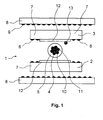
- Fig. 1 shows a cable comprising a textile composite 1 of a support layer 2 and a cover layer 3, wherein between the support layer 2 and the cover layer 3 at least one electrical line 4 is added and wherein the textile composite 1 is destructively flexible deformable.
- the electrical line 4 is electrically insulated from the carrier layer 2 and the cover layer 3 by an insulation 5.
- the carrier layer 2 and the cover layer 3 are reversibly compressible.
- the cable according to Fig. 1 is characterized by an elastic extensibility in the longitudinal direction, ie in the direction of the line 4, from.
- the carrier layer 2 and the cover layer 3 are connected by adhesive dots 6 at points.
- the carrier layer 2 and the cover layer 3 are configured as nonwovens.
- the nonwovens consist of split fibers, the made of bicomponent fibers.
- non-woven fabrics of the type having the trade designation EVOLON having a basis weight of 60 g / m 2 were used.
- the composite 1 therefore has porous regions which are made permeable to air.
- the porous regions 7 are at least between the adhesive dots 6.
- the composite 1 is embedded between two envelopes 8.
- the two envelopes 8 are also connected via adhesive dots 9 selectively with each other and with the composite 1.
- the electrical line 4 is designed as a strand 10.
- the strand 10 consists of a plurality of individual wires 11, which are twisted together.
- the electrical line 4, which is electrically insulated by the insulation 5, is surrounded by an electrical shield 12.
- the electrical shield 12 is designed in particular as a conductive shielding paste. In the conductive Ablepaste a bare wire 13 is embedded.
- the electrical shield 12 abuts directly on the electrical line 4 and is applied on the sides of the carrier layer 2 or cover layer 3, which face the electrical line 4.
- the carrier layer 2 and the cover layer 3 could also be configured as a foam, which exhibits sufficient compressibility and elastic extensibility in the longitudinal direction. The same applies to the enveloping layers 8. It is also conceivable to manufacture the enveloping layers 8 from a nonwoven fabric from which the carrier layer 2 or cover layer 3 is also made.
- Fig. 2 shows a cable with an analogous structure of the cable according to Fig. 1 , wherein as electrical line 4, a single wire 14 is used, which is surrounded by an insulation 5. The wire 14 is thereby protected against moisture.
- the cable shows according to Fig. 2 the same structure as the cable according to Fig. 1 , To avoid repetition, be on it noted that in the Fig. 1 and Fig. 2 like reference characters designate like components of the cable.
- Fig. 3 shows a cable comprising a textile composite 1 of a support layer 2 and a cover layer 3, wherein between the support layer 2 and the cover layer 3 at least one electrical line 4 is added and wherein the textile composite 1 is destructively flexible deformable.
- the electrical line 4 is electrically insulated from the carrier layer 2 and the cover layer 3 by an insulation 5.
- the carrier layer 2 and the cover layer 3 are reversibly compressible.
- the cable according to Fig. 3 is characterized by an elastic extensibility in the longitudinal direction.
- the carrier layer 2 and the cover layer 3 are selectively connected to each other by welding points 6a.
- the welding points 6a were generated by ultrasonic welding.
- the carrier layer 2 and the cover layer 3 are configured as nonwovens.
- the nonwovens consist of split fibers made of bicomponent fibers.
- nonwoven fabrics of the type for example of the trade name EVOLON having a basis weight of 60 g / m 2 were used.
- the composite 1 therefore has porous regions which are made permeable to air.
- the porous regions 7 are at least between the welding points 6a.
- the composite 1 is embedded between two envelopes 8.
- the two envelopes 8 are also connected via welding points 9a selectively with each other and with the textile composite 1.
- the welding points 9a were generated by ultrasonic welding.
- the electrical line 4 is designed in particular as a strand 10.
- the strand 10 consists of a plurality of individual wires 11, which are twisted together.
- the electrical line 4, which is electrically insulated by the insulation 5, is surrounded by an electrical shield 12.
- the electrical shield 12 is preferably designed as a conductive shielding paste. In the conductive Ablepaste a bare wire 13 is embedded.
- the electrical shield 12 is applied directly to the electrical line 4 and is applied to the sides of the carrier layer 2 and cover layer 3, which are facing the electrical line 4.
- each cable exhibits elastic extensibility at least in the longitudinal direction of up to 15% of the initial length.
- nonwoven fabrics for the carrier layer 2, the cover layer 3 and the enveloping layers 8 for example, a nonwoven fabric of the type EVOLON Freudenberg nonwovens KG, 69469 Weinheim, DE was used. The nonwovens showed a basis weight of 60 g / m 2 .
- a folded structure of the composite 1 can be used to adjust the length of the cable for different body sizes and body shapes, for example, for premature and neonatal patients on the one hand and for large and vigorous adult patients on the other hand.
- the length of the stretched composite 1 can thus be for example 15 to 50% greater than in the folded, unstretched state.
Landscapes
- Insulated Conductors (AREA)
Applications Claiming Priority (1)
| Application Number | Priority Date | Filing Date | Title |
|---|---|---|---|
| DE102009005416 | 2009-01-19 |
Publications (2)
| Publication Number | Publication Date |
|---|---|
| EP2209126A2 true EP2209126A2 (fr) | 2010-07-21 |
| EP2209126A3 EP2209126A3 (fr) | 2012-04-04 |
Family
ID=42109965
Family Applications (1)
| Application Number | Title | Priority Date | Filing Date |
|---|---|---|---|
| EP09012223A Withdrawn EP2209126A3 (fr) | 2009-01-19 | 2009-09-25 | Câble déformable flexible doté d'un composite textile pour des applications électromédicales |
Country Status (3)
| Country | Link |
|---|---|
| US (1) | US20100185107A1 (fr) |
| EP (1) | EP2209126A3 (fr) |
| CN (1) | CN101783202A (fr) |
Families Citing this family (4)
| Publication number | Priority date | Publication date | Assignee | Title |
|---|---|---|---|---|
| DE102011078734A1 (de) * | 2011-07-06 | 2013-01-10 | Robert Bosch Gmbh | Komponente eines Brennstoffeinspritzsystems und Brennstoffeinspritzsystem |
| JP5920181B2 (ja) * | 2012-11-15 | 2016-05-18 | 住友電装株式会社 | ワイヤーハーネス及びワイヤーハーネスの製造方法 |
| FR3040826B1 (fr) * | 2015-09-04 | 2017-08-18 | Renault Sas | Dispositif de protection pour cables d'alimentation d'un groupe motopropulseur electrique |
| CN111281612B (zh) * | 2019-12-30 | 2022-05-27 | 雅博尼西医疗科技(苏州)有限公司 | 一种有多孔性表面结构的假体 |
Citations (2)
| Publication number | Priority date | Publication date | Assignee | Title |
|---|---|---|---|---|
| US5341806A (en) | 1991-04-18 | 1994-08-30 | Physio-Control Corporation | Multiple electrode strip |
| DE102004007875B3 (de) | 2004-02-17 | 2005-09-15 | Carl Freudenberg Kg | Dreidimensional geformtes Flachkabel |
Family Cites Families (13)
| Publication number | Priority date | Publication date | Assignee | Title |
|---|---|---|---|---|
| US2434793A (en) * | 1944-11-11 | 1948-01-20 | Edward B Feaster | Electric cord |
| GB973211A (en) * | 1959-12-11 | 1964-10-21 | Eisler Paul | Electric tape cables |
| US4281211A (en) * | 1979-04-13 | 1981-07-28 | Southern Weaving Company | Woven cover for electrical transmission cable |
| US4353372A (en) * | 1980-02-11 | 1982-10-12 | Bunker Ramo Corporation | Medical cable set and electrode therefor |
| US5502287A (en) * | 1993-03-10 | 1996-03-26 | Raychem Corporation | Multi-component cable assembly |
| US5552565A (en) * | 1995-03-31 | 1996-09-03 | Hewlett-Packard Company | Multiconductor shielded transducer cable |
| FI962544A7 (fi) * | 1996-06-19 | 1997-12-20 | Oy Iws Int Inc | Lattakaapeli ja menetelmä sen valmistamiseksi |
| DE19728940A1 (de) * | 1997-07-07 | 1999-01-14 | Alsthom Cge Alcatel | Kabel mit leitfähiger Schicht |
| US6730622B2 (en) * | 1999-12-21 | 2004-05-04 | The Procter & Gamble Company | Electrical cable |
| US7091422B1 (en) * | 2005-01-28 | 2006-08-15 | Multek Flexible Circuits, Inc. | Flexible flat cable with insulating layer having distinct adhesives on opposing faces |
| CN100553032C (zh) * | 2005-03-30 | 2009-10-21 | 松下电器产业株式会社 | 传输线对 |
| TWM342597U (en) * | 2008-05-08 | 2008-10-11 | Tennrich Int Corp | Easily flexible transmission line with improved characteristic impedance |
| DE102009005404A1 (de) * | 2009-01-19 | 2010-07-22 | Carl Freudenberg Kg | Flexibel deformierbares Kabel mit textilem Verbund |
-
2009
- 2009-09-25 EP EP09012223A patent/EP2209126A3/fr not_active Withdrawn
-
2010
- 2010-01-15 US US12/688,174 patent/US20100185107A1/en not_active Abandoned
- 2010-01-19 CN CN201010119385A patent/CN101783202A/zh active Pending
Patent Citations (2)
| Publication number | Priority date | Publication date | Assignee | Title |
|---|---|---|---|---|
| US5341806A (en) | 1991-04-18 | 1994-08-30 | Physio-Control Corporation | Multiple electrode strip |
| DE102004007875B3 (de) | 2004-02-17 | 2005-09-15 | Carl Freudenberg Kg | Dreidimensional geformtes Flachkabel |
Also Published As
| Publication number | Publication date |
|---|---|
| CN101783202A (zh) | 2010-07-21 |
| US20100185107A1 (en) | 2010-07-22 |
| EP2209126A3 (fr) | 2012-04-04 |
Similar Documents
| Publication | Publication Date | Title |
|---|---|---|
| EP3051926B1 (fr) | Dispositif de production de plasma, systeme de production de plasma, procede de production de plasma et procede de desinfection de surfaces | |
| EP3292885B1 (fr) | Système de conducteur d'électrode élastique et implant médical | |
| DE60307063T2 (de) | Leitfähige faser | |
| DE69329197T2 (de) | Elektroden-anordnung mit einmal-gel | |
| DE112011102168B4 (de) | Medizinische elektrische Kabelanordnung und deren Verwendung, EKG-Kabel und Elektrokardiographie (EKG)-Anordnung | |
| EP3784327B1 (fr) | Corps d'électrode d'un ensemble d'électrodes et ensemble d'électrodes de stimulation électrique et procédé de fabrication d'un ensemble d'électrodes | |
| DE102011101583B4 (de) | Elektrode zum transkutanen Übertragen elektrischer Signale und Verfahren zum Herstellen einer solchen | |
| WO2014090927A1 (fr) | Électrode à base de textile et procédé de fabrication et utilisation de ladite électrode | |
| EP0954266B1 (fr) | Bandage preforme auto-adhesif pour limiter l'extension ou la flexion de l'articulation metacarpophalangienne du doigt et celle du poignet | |
| EP3541469B1 (fr) | Structure de connexion multipolaire électrique implantable | |
| EP2053965A1 (fr) | Dispositif textile a electrodes, en particulier pour l'electrostimulation multicanal ou des mesures electrophysiologiques, et procede pour sa fabrication | |
| EP2209126A2 (fr) | Câble déformable flexible doté d'un composite textile pour des applications électromédicales | |
| DE102016109568B4 (de) | Elektrode zur Elektromuskelstimulierung, Bekleidungsstück, Verfahren zur Herstellung eines Bekleidungsstücks sowie Verwendung einer Elektrode | |
| EP3756725A1 (fr) | Conduite d'électrode pouvant être implantée pourvue de conducteur raccordé à un treillis | |
| WO2016016273A1 (fr) | Dispositif générateur de plasma | |
| DE102008048984A1 (de) | Sensor zur Erfassung von elektrischen Biopotentialen | |
| DE69027527T2 (de) | Elektrische reizelektrode mit impedanzausgleich | |
| DE202006007226U1 (de) | Textilelektrode | |
| DE102013219513A1 (de) | Sensor zur berührungslosen elektrokardiographischen Messung, Sensorarray und Sitz oder Liege | |
| EP2456282A1 (fr) | Maillage à écartement à des fins de chauffage, son procédé de fabrication et son utilisation | |
| DE102004022373B4 (de) | Mehrschichtiges übernähtes System | |
| DE202013100966U1 (de) | Dreidimensionale, leitfähige Gewebeanordnung | |
| DE102009005404A1 (de) | Flexibel deformierbares Kabel mit textilem Verbund | |
| DE102009014697A1 (de) | Heizelement und dessen Verwendung | |
| DE102019103935B4 (de) | Heizeinlage in Form eines Abstandsgewirkeabschnittes sowie beheizbares Interieurbauteil |
Legal Events
| Date | Code | Title | Description |
|---|---|---|---|
| PUAI | Public reference made under article 153(3) epc to a published international application that has entered the european phase |
Free format text: ORIGINAL CODE: 0009012 |
|
| AK | Designated contracting states |
Kind code of ref document: A2 Designated state(s): AT BE BG CH CY CZ DE DK EE ES FI FR GB GR HR HU IE IS IT LI LT LU LV MC MK MT NL NO PL PT RO SE SI SK SM TR |
|
| AX | Request for extension of the european patent |
Extension state: AL BA RS |
|
| 17P | Request for examination filed |
Effective date: 20100705 |
|
| RAP1 | Party data changed (applicant data changed or rights of an application transferred) |
Owner name: DRAEGER MEDICAL GMBH |
|
| PUAL | Search report despatched |
Free format text: ORIGINAL CODE: 0009013 |
|
| AK | Designated contracting states |
Kind code of ref document: A3 Designated state(s): AT BE BG CH CY CZ DE DK EE ES FI FR GB GR HR HU IE IS IT LI LT LU LV MC MK MT NL NO PL PT RO SE SI SK SM TR |
|
| AX | Request for extension of the european patent |
Extension state: AL BA RS |
|
| RIC1 | Information provided on ipc code assigned before grant |
Ipc: H01B 7/08 20060101ALI20120229BHEP Ipc: H01B 7/04 20060101AFI20120229BHEP |
|
| STAA | Information on the status of an ep patent application or granted ep patent |
Free format text: STATUS: THE APPLICATION IS DEEMED TO BE WITHDRAWN |
|
| 18D | Application deemed to be withdrawn |
Effective date: 20121005 |