EP2209660B1 - Vorrichtung zur leistungsübertragung zwischen dem ausgang eines wärmemotors und einer radachse sowie verwendung dieser vorrichtung - Google Patents
Vorrichtung zur leistungsübertragung zwischen dem ausgang eines wärmemotors und einer radachse sowie verwendung dieser vorrichtung Download PDFInfo
- Publication number
- EP2209660B1 EP2209660B1 EP08855726A EP08855726A EP2209660B1 EP 2209660 B1 EP2209660 B1 EP 2209660B1 EP 08855726 A EP08855726 A EP 08855726A EP 08855726 A EP08855726 A EP 08855726A EP 2209660 B1 EP2209660 B1 EP 2209660B1
- Authority
- EP
- European Patent Office
- Prior art keywords
- gear
- machine
- shaft
- stator
- ratio
- Prior art date
- Legal status (The legal status is an assumption and is not a legal conclusion. Google has not performed a legal analysis and makes no representation as to the accuracy of the status listed.)
- Not-in-force
Links
Images



Classifications
-
- B—PERFORMING OPERATIONS; TRANSPORTING
- B60—VEHICLES IN GENERAL
- B60K—ARRANGEMENT OR MOUNTING OF PROPULSION UNITS OR OF TRANSMISSIONS IN VEHICLES; ARRANGEMENT OR MOUNTING OF PLURAL DIVERSE PRIME-MOVERS IN VEHICLES; AUXILIARY DRIVES FOR VEHICLES; INSTRUMENTATION OR DASHBOARDS FOR VEHICLES; ARRANGEMENTS IN CONNECTION WITH COOLING, AIR INTAKE, GAS EXHAUST OR FUEL SUPPLY OF PROPULSION UNITS IN VEHICLES
- B60K6/00—Arrangement or mounting of plural diverse prime-movers for mutual or common propulsion, e.g. hybrid propulsion systems comprising electric motors and internal combustion engines
- B60K6/20—Arrangement or mounting of plural diverse prime-movers for mutual or common propulsion, e.g. hybrid propulsion systems comprising electric motors and internal combustion engines the prime-movers consisting of electric motors and internal combustion engines, e.g. HEVs
- B60K6/42—Arrangement or mounting of plural diverse prime-movers for mutual or common propulsion, e.g. hybrid propulsion systems comprising electric motors and internal combustion engines the prime-movers consisting of electric motors and internal combustion engines, e.g. HEVs characterised by the architecture of the hybrid electric vehicle
- B60K6/44—Series-parallel type
- B60K6/448—Electrical distribution type
-
- B—PERFORMING OPERATIONS; TRANSPORTING
- B60—VEHICLES IN GENERAL
- B60K—ARRANGEMENT OR MOUNTING OF PROPULSION UNITS OR OF TRANSMISSIONS IN VEHICLES; ARRANGEMENT OR MOUNTING OF PLURAL DIVERSE PRIME-MOVERS IN VEHICLES; AUXILIARY DRIVES FOR VEHICLES; INSTRUMENTATION OR DASHBOARDS FOR VEHICLES; ARRANGEMENTS IN CONNECTION WITH COOLING, AIR INTAKE, GAS EXHAUST OR FUEL SUPPLY OF PROPULSION UNITS IN VEHICLES
- B60K6/00—Arrangement or mounting of plural diverse prime-movers for mutual or common propulsion, e.g. hybrid propulsion systems comprising electric motors and internal combustion engines
- B60K6/20—Arrangement or mounting of plural diverse prime-movers for mutual or common propulsion, e.g. hybrid propulsion systems comprising electric motors and internal combustion engines the prime-movers consisting of electric motors and internal combustion engines, e.g. HEVs
- B60K6/22—Arrangement or mounting of plural diverse prime-movers for mutual or common propulsion, e.g. hybrid propulsion systems comprising electric motors and internal combustion engines the prime-movers consisting of electric motors and internal combustion engines, e.g. HEVs characterised by apparatus, components or means specially adapted for HEVs
- B60K6/36—Arrangement or mounting of plural diverse prime-movers for mutual or common propulsion, e.g. hybrid propulsion systems comprising electric motors and internal combustion engines the prime-movers consisting of electric motors and internal combustion engines, e.g. HEVs characterised by apparatus, components or means specially adapted for HEVs characterised by the transmission gearings
- B60K6/365—Arrangement or mounting of plural diverse prime-movers for mutual or common propulsion, e.g. hybrid propulsion systems comprising electric motors and internal combustion engines the prime-movers consisting of electric motors and internal combustion engines, e.g. HEVs characterised by apparatus, components or means specially adapted for HEVs characterised by the transmission gearings with the gears having orbital motion
-
- B—PERFORMING OPERATIONS; TRANSPORTING
- B60—VEHICLES IN GENERAL
- B60K—ARRANGEMENT OR MOUNTING OF PROPULSION UNITS OR OF TRANSMISSIONS IN VEHICLES; ARRANGEMENT OR MOUNTING OF PLURAL DIVERSE PRIME-MOVERS IN VEHICLES; AUXILIARY DRIVES FOR VEHICLES; INSTRUMENTATION OR DASHBOARDS FOR VEHICLES; ARRANGEMENTS IN CONNECTION WITH COOLING, AIR INTAKE, GAS EXHAUST OR FUEL SUPPLY OF PROPULSION UNITS IN VEHICLES
- B60K6/00—Arrangement or mounting of plural diverse prime-movers for mutual or common propulsion, e.g. hybrid propulsion systems comprising electric motors and internal combustion engines
- B60K6/20—Arrangement or mounting of plural diverse prime-movers for mutual or common propulsion, e.g. hybrid propulsion systems comprising electric motors and internal combustion engines the prime-movers consisting of electric motors and internal combustion engines, e.g. HEVs
- B60K6/22—Arrangement or mounting of plural diverse prime-movers for mutual or common propulsion, e.g. hybrid propulsion systems comprising electric motors and internal combustion engines the prime-movers consisting of electric motors and internal combustion engines, e.g. HEVs characterised by apparatus, components or means specially adapted for HEVs
- B60K6/38—Arrangement or mounting of plural diverse prime-movers for mutual or common propulsion, e.g. hybrid propulsion systems comprising electric motors and internal combustion engines the prime-movers consisting of electric motors and internal combustion engines, e.g. HEVs characterised by apparatus, components or means specially adapted for HEVs characterised by the driveline clutches
- B60K6/387—Actuated clutches, i.e. clutches engaged or disengaged by electric, hydraulic or mechanical actuating means
-
- B—PERFORMING OPERATIONS; TRANSPORTING
- B60—VEHICLES IN GENERAL
- B60K—ARRANGEMENT OR MOUNTING OF PROPULSION UNITS OR OF TRANSMISSIONS IN VEHICLES; ARRANGEMENT OR MOUNTING OF PLURAL DIVERSE PRIME-MOVERS IN VEHICLES; AUXILIARY DRIVES FOR VEHICLES; INSTRUMENTATION OR DASHBOARDS FOR VEHICLES; ARRANGEMENTS IN CONNECTION WITH COOLING, AIR INTAKE, GAS EXHAUST OR FUEL SUPPLY OF PROPULSION UNITS IN VEHICLES
- B60K6/00—Arrangement or mounting of plural diverse prime-movers for mutual or common propulsion, e.g. hybrid propulsion systems comprising electric motors and internal combustion engines
- B60K6/20—Arrangement or mounting of plural diverse prime-movers for mutual or common propulsion, e.g. hybrid propulsion systems comprising electric motors and internal combustion engines the prime-movers consisting of electric motors and internal combustion engines, e.g. HEVs
- B60K6/42—Arrangement or mounting of plural diverse prime-movers for mutual or common propulsion, e.g. hybrid propulsion systems comprising electric motors and internal combustion engines the prime-movers consisting of electric motors and internal combustion engines, e.g. HEVs characterised by the architecture of the hybrid electric vehicle
- B60K6/44—Series-parallel type
- B60K6/445—Differential gearing distribution type
-
- F—MECHANICAL ENGINEERING; LIGHTING; HEATING; WEAPONS; BLASTING
- F16—ENGINEERING ELEMENTS AND UNITS; GENERAL MEASURES FOR PRODUCING AND MAINTAINING EFFECTIVE FUNCTIONING OF MACHINES OR INSTALLATIONS; THERMAL INSULATION IN GENERAL
- F16H—GEARING
- F16H3/00—Toothed gearings for conveying rotary motion with variable gear ratio or for reversing rotary motion
- F16H3/44—Toothed gearings for conveying rotary motion with variable gear ratio or for reversing rotary motion using gears having orbital motion
- F16H3/72—Toothed gearings for conveying rotary motion with variable gear ratio or for reversing rotary motion using gears having orbital motion with a secondary drive, e.g. regulating motor, in order to vary speed continuously
- F16H3/727—Toothed gearings for conveying rotary motion with variable gear ratio or for reversing rotary motion using gears having orbital motion with a secondary drive, e.g. regulating motor, in order to vary speed continuously with at least two dynamo electric machines for creating an electric power path inside the gearing, e.g. using generator and motor for a variable power torque path
- F16H3/728—Toothed gearings for conveying rotary motion with variable gear ratio or for reversing rotary motion using gears having orbital motion with a secondary drive, e.g. regulating motor, in order to vary speed continuously with at least two dynamo electric machines for creating an electric power path inside the gearing, e.g. using generator and motor for a variable power torque path with means to change ratio in the mechanical gearing
-
- B—PERFORMING OPERATIONS; TRANSPORTING
- B60—VEHICLES IN GENERAL
- B60K—ARRANGEMENT OR MOUNTING OF PROPULSION UNITS OR OF TRANSMISSIONS IN VEHICLES; ARRANGEMENT OR MOUNTING OF PLURAL DIVERSE PRIME-MOVERS IN VEHICLES; AUXILIARY DRIVES FOR VEHICLES; INSTRUMENTATION OR DASHBOARDS FOR VEHICLES; ARRANGEMENTS IN CONNECTION WITH COOLING, AIR INTAKE, GAS EXHAUST OR FUEL SUPPLY OF PROPULSION UNITS IN VEHICLES
- B60K6/00—Arrangement or mounting of plural diverse prime-movers for mutual or common propulsion, e.g. hybrid propulsion systems comprising electric motors and internal combustion engines
- B60K6/20—Arrangement or mounting of plural diverse prime-movers for mutual or common propulsion, e.g. hybrid propulsion systems comprising electric motors and internal combustion engines the prime-movers consisting of electric motors and internal combustion engines, e.g. HEVs
- B60K6/22—Arrangement or mounting of plural diverse prime-movers for mutual or common propulsion, e.g. hybrid propulsion systems comprising electric motors and internal combustion engines the prime-movers consisting of electric motors and internal combustion engines, e.g. HEVs characterised by apparatus, components or means specially adapted for HEVs
- B60K6/26—Arrangement or mounting of plural diverse prime-movers for mutual or common propulsion, e.g. hybrid propulsion systems comprising electric motors and internal combustion engines the prime-movers consisting of electric motors and internal combustion engines, e.g. HEVs characterised by apparatus, components or means specially adapted for HEVs characterised by the motors or the generators
- B60K2006/262—Arrangement or mounting of plural diverse prime-movers for mutual or common propulsion, e.g. hybrid propulsion systems comprising electric motors and internal combustion engines the prime-movers consisting of electric motors and internal combustion engines, e.g. HEVs characterised by apparatus, components or means specially adapted for HEVs characterised by the motors or the generators the motor or generator are used as clutch, e.g. between engine and driveshaft
-
- F—MECHANICAL ENGINEERING; LIGHTING; HEATING; WEAPONS; BLASTING
- F16—ENGINEERING ELEMENTS AND UNITS; GENERAL MEASURES FOR PRODUCING AND MAINTAINING EFFECTIVE FUNCTIONING OF MACHINES OR INSTALLATIONS; THERMAL INSULATION IN GENERAL
- F16H—GEARING
- F16H37/00—Combinations of mechanical gearings, not provided for in groups F16H1/00 - F16H35/00
- F16H37/02—Combinations of mechanical gearings, not provided for in groups F16H1/00 - F16H35/00 comprising essentially only toothed or friction gearings
- F16H37/06—Combinations of mechanical gearings, not provided for in groups F16H1/00 - F16H35/00 comprising essentially only toothed or friction gearings with a plurality of driving or driven shafts; with arrangements for dividing torque between two or more intermediate shafts
- F16H37/08—Combinations of mechanical gearings, not provided for in groups F16H1/00 - F16H35/00 comprising essentially only toothed or friction gearings with a plurality of driving or driven shafts; with arrangements for dividing torque between two or more intermediate shafts with differential gearing
- F16H37/0833—Combinations of mechanical gearings, not provided for in groups F16H1/00 - F16H35/00 comprising essentially only toothed or friction gearings with a plurality of driving or driven shafts; with arrangements for dividing torque between two or more intermediate shafts with differential gearing with arrangements for dividing torque between two or more intermediate shafts, i.e. with two or more internal power paths
- F16H37/084—Combinations of mechanical gearings, not provided for in groups F16H1/00 - F16H35/00 comprising essentially only toothed or friction gearings with a plurality of driving or driven shafts; with arrangements for dividing torque between two or more intermediate shafts with differential gearing with arrangements for dividing torque between two or more intermediate shafts, i.e. with two or more internal power paths at least one power path being a continuously variable transmission, i.e. CVT
- F16H2037/0866—Power-split transmissions with distributing differentials, with the output of the CVT connected or connectable to the output shaft
-
- F—MECHANICAL ENGINEERING; LIGHTING; HEATING; WEAPONS; BLASTING
- F16—ENGINEERING ELEMENTS AND UNITS; GENERAL MEASURES FOR PRODUCING AND MAINTAINING EFFECTIVE FUNCTIONING OF MACHINES OR INSTALLATIONS; THERMAL INSULATION IN GENERAL
- F16H—GEARING
- F16H37/00—Combinations of mechanical gearings, not provided for in groups F16H1/00 - F16H35/00
- F16H37/02—Combinations of mechanical gearings, not provided for in groups F16H1/00 - F16H35/00 comprising essentially only toothed or friction gearings
- F16H37/06—Combinations of mechanical gearings, not provided for in groups F16H1/00 - F16H35/00 comprising essentially only toothed or friction gearings with a plurality of driving or driven shafts; with arrangements for dividing torque between two or more intermediate shafts
- F16H37/08—Combinations of mechanical gearings, not provided for in groups F16H1/00 - F16H35/00 comprising essentially only toothed or friction gearings with a plurality of driving or driven shafts; with arrangements for dividing torque between two or more intermediate shafts with differential gearing
- F16H37/0833—Combinations of mechanical gearings, not provided for in groups F16H1/00 - F16H35/00 comprising essentially only toothed or friction gearings with a plurality of driving or driven shafts; with arrangements for dividing torque between two or more intermediate shafts with differential gearing with arrangements for dividing torque between two or more intermediate shafts, i.e. with two or more internal power paths
- F16H37/084—Combinations of mechanical gearings, not provided for in groups F16H1/00 - F16H35/00 comprising essentially only toothed or friction gearings with a plurality of driving or driven shafts; with arrangements for dividing torque between two or more intermediate shafts with differential gearing with arrangements for dividing torque between two or more intermediate shafts, i.e. with two or more internal power paths at least one power path being a continuously variable transmission, i.e. CVT
- F16H2037/088—Power-split transmissions with summing differentials, with the input of the CVT connected or connectable to the input shaft
-
- F—MECHANICAL ENGINEERING; LIGHTING; HEATING; WEAPONS; BLASTING
- F16—ENGINEERING ELEMENTS AND UNITS; GENERAL MEASURES FOR PRODUCING AND MAINTAINING EFFECTIVE FUNCTIONING OF MACHINES OR INSTALLATIONS; THERMAL INSULATION IN GENERAL
- F16H—GEARING
- F16H37/00—Combinations of mechanical gearings, not provided for in groups F16H1/00 - F16H35/00
- F16H37/02—Combinations of mechanical gearings, not provided for in groups F16H1/00 - F16H35/00 comprising essentially only toothed or friction gearings
- F16H37/06—Combinations of mechanical gearings, not provided for in groups F16H1/00 - F16H35/00 comprising essentially only toothed or friction gearings with a plurality of driving or driven shafts; with arrangements for dividing torque between two or more intermediate shafts
- F16H37/08—Combinations of mechanical gearings, not provided for in groups F16H1/00 - F16H35/00 comprising essentially only toothed or friction gearings with a plurality of driving or driven shafts; with arrangements for dividing torque between two or more intermediate shafts with differential gearing
- F16H37/10—Combinations of mechanical gearings, not provided for in groups F16H1/00 - F16H35/00 comprising essentially only toothed or friction gearings with a plurality of driving or driven shafts; with arrangements for dividing torque between two or more intermediate shafts with differential gearing at both ends of intermediate shafts
- F16H2037/103—Power-split transmissions with each end of a CVT connected or connectable to a planetary gear set having four or more connections, e.g. a Ravigneaux set
-
- F—MECHANICAL ENGINEERING; LIGHTING; HEATING; WEAPONS; BLASTING
- F16—ENGINEERING ELEMENTS AND UNITS; GENERAL MEASURES FOR PRODUCING AND MAINTAINING EFFECTIVE FUNCTIONING OF MACHINES OR INSTALLATIONS; THERMAL INSULATION IN GENERAL
- F16H—GEARING
- F16H37/00—Combinations of mechanical gearings, not provided for in groups F16H1/00 - F16H35/00
- F16H37/02—Combinations of mechanical gearings, not provided for in groups F16H1/00 - F16H35/00 comprising essentially only toothed or friction gearings
- F16H37/06—Combinations of mechanical gearings, not provided for in groups F16H1/00 - F16H35/00 comprising essentially only toothed or friction gearings with a plurality of driving or driven shafts; with arrangements for dividing torque between two or more intermediate shafts
- F16H37/08—Combinations of mechanical gearings, not provided for in groups F16H1/00 - F16H35/00 comprising essentially only toothed or friction gearings with a plurality of driving or driven shafts; with arrangements for dividing torque between two or more intermediate shafts with differential gearing
- F16H37/10—Combinations of mechanical gearings, not provided for in groups F16H1/00 - F16H35/00 comprising essentially only toothed or friction gearings with a plurality of driving or driven shafts; with arrangements for dividing torque between two or more intermediate shafts with differential gearing at both ends of intermediate shafts
- F16H2037/105—Combinations of mechanical gearings, not provided for in groups F16H1/00 - F16H35/00 comprising essentially only toothed or friction gearings with a plurality of driving or driven shafts; with arrangements for dividing torque between two or more intermediate shafts with differential gearing at both ends of intermediate shafts characterised by number of modes or ranges, e.g. for compound gearing
- F16H2037/106—Combinations of mechanical gearings, not provided for in groups F16H1/00 - F16H35/00 comprising essentially only toothed or friction gearings with a plurality of driving or driven shafts; with arrangements for dividing torque between two or more intermediate shafts with differential gearing at both ends of intermediate shafts characterised by number of modes or ranges, e.g. for compound gearing with switching means to provide two variator modes or ranges
-
- F—MECHANICAL ENGINEERING; LIGHTING; HEATING; WEAPONS; BLASTING
- F16—ENGINEERING ELEMENTS AND UNITS; GENERAL MEASURES FOR PRODUCING AND MAINTAINING EFFECTIVE FUNCTIONING OF MACHINES OR INSTALLATIONS; THERMAL INSULATION IN GENERAL
- F16H—GEARING
- F16H2200/00—Transmissions for multiple ratios
- F16H2200/20—Transmissions using gears with orbital motion
- F16H2200/202—Transmissions using gears with orbital motion characterised by the type of Ravigneaux set
- F16H2200/2023—Transmissions using gears with orbital motion characterised by the type of Ravigneaux set using a Ravigneaux set with 4 connections
-
- F—MECHANICAL ENGINEERING; LIGHTING; HEATING; WEAPONS; BLASTING
- F16—ENGINEERING ELEMENTS AND UNITS; GENERAL MEASURES FOR PRODUCING AND MAINTAINING EFFECTIVE FUNCTIONING OF MACHINES OR INSTALLATIONS; THERMAL INSULATION IN GENERAL
- F16H—GEARING
- F16H2200/00—Transmissions for multiple ratios
- F16H2200/20—Transmissions using gears with orbital motion
- F16H2200/203—Transmissions using gears with orbital motion characterised by the engaging friction means not of the freewheel type, e.g. friction clutches or brakes
- F16H2200/2035—Transmissions using gears with orbital motion characterised by the engaging friction means not of the freewheel type, e.g. friction clutches or brakes with two engaging means
-
- Y—GENERAL TAGGING OF NEW TECHNOLOGICAL DEVELOPMENTS; GENERAL TAGGING OF CROSS-SECTIONAL TECHNOLOGIES SPANNING OVER SEVERAL SECTIONS OF THE IPC; TECHNICAL SUBJECTS COVERED BY FORMER USPC CROSS-REFERENCE ART COLLECTIONS [XRACs] AND DIGESTS
- Y02—TECHNOLOGIES OR APPLICATIONS FOR MITIGATION OR ADAPTATION AGAINST CLIMATE CHANGE
- Y02T—CLIMATE CHANGE MITIGATION TECHNOLOGIES RELATED TO TRANSPORTATION
- Y02T10/00—Road transport of goods or passengers
- Y02T10/60—Other road transportation technologies with climate change mitigation effect
- Y02T10/62—Hybrid vehicles
Definitions
- the present invention relates to a device for transmitting power between an output of a heat engine and a wheel shaft, as well as the use of this device.
- the invention particularly aims to limit the size and cost of such a device.
- the invention finds a particularly advantageous, but not exclusive, application in the field of hybrid motor vehicles with power bypass.
- a power transmission device 1 comprises an input shaft 2 connected to a source 3 of mechanical power (generally a heat engine) and an output shaft 4 connected to the wheels 5 of the vehicle.
- This device 1 comprises two electrical machines 6, 7 interconnected by an electrical chain 11, and a mechanical assembly 12 providing the connection between the power source 3, the wheels 5 of the vehicle, and the two electric machines 6, 7.
- the power of the source 3 is either transmitted to the wheels 5, or derived to the electrical machines 6, 7 may behave as a motor or generator according to energy values received electrically and / or mechanically respectively on their terminals and their shaft .
- the derived power is retransmitted to the wheels 5 of the vehicle or stored, if necessary, in a battery connected to the electrical chain.
- This derived power makes it possible to precisely adapt the torque applied to the wheels 5 of the vehicle to that requested by a driver, while also precisely adapting the torque and speed of the engine so as to optimize its efficiency.
- the invention proposes to limit the use of the use of epicyclic gear trains which are mechanical elements whose design and implementation are complex.
- the invention consists in replacing the machines whose rotor is connected to the epicyclic gear train and the stator to the casing of the transmission, by machines comprising a rotating rotor and stator connected to the inlet and the outlet of the transmission. transmission.
- the advantage of the invention is of an economic nature, the suppression of one or more epicyclic gear trains in a power-bypass transmission making it possible to reduce substantially the manufacturing cost of the transmission device.
- by removing at least one epicyclic train of the mechanical assembly it limits its size.
- the invention therefore relates to a power transmission device according to claim 1.
- the two electrical machines being rotating stator, the mechanical assembly is devoid of epicyclic gear.
- the mechanical assembly comprises only an epicyclic train formed by a sun gear, a planet carrier carrying satellites and a ring gear meshing with each other.
- the input shaft is directly connected to the planet carrier and the output shaft is connected to an intermediate shaft via a ⁇ l downshift, this intermediate shaft being connected to the ring gear via a gearbox. ⁇ 0 ratio.
- the shaft of the stationary stator machine may be selectively connected to the ring gear via a gear ratio r2 or to the sun gear via a gear ratio r3.
- the stator of the rotating stator machine is connected to the input shaft via a ratio gear q2, and the rotor of the rotating stator machine is connected to the sun gear via a ratio gear q1.
- the output shaft is connected to an intermediate shaft via a bridge descent ratio ⁇ 1, the intermediate shaft being itself linked to the input shaft via a ratio gear ⁇ 0.
- the rotor of the first machine is connected to the wheels via a ratio gear q1
- the stator of this machine is connected to the input shaft via a ratio gear q2.
- the rotor of the second machine is capable of being selectively linked to the output shaft via a ratio gear r2 or via a ratio gear q3, respectively by means of a first clutch and a second gear. clutch, the stator of this second machine being capable of being selectively linked to the input shaft via a ratio gear q4 or the fixed frame respectively by means of a third clutch and a fourth clutch.
- the first dog clutch in order to switch from the coupled output mode to the combined mode, the first dog clutch is disengaged while keeping the fourth dog engaged, the rotor speed of the second machine is synchronized with an idle gear associated with the second clutch, and then engages this second clutch, disengage the fourth clutch, synchronize the speed of the stator of the machine with the pinion associated with the clutch and engage the clutch with this pinion.
- to switch from the combined mode to the mode coupled output disengaging the third clutch and stopping the stator of the second machine so as to engage the fourth dog with the pinion to which it is associated, and opens the second clutch, synchronizes the rotor of the second machine with the pinion associable with the first clutch and engage the first clutch with this pinion.
- Figure 1 (already described): a schematic representation of the architecture of a power bypass transmission device
- FIG. 2 Kinematic diagrams of single-mode transmission devices according to the state of the art and their equivalent according to the invention
- Figures 3 kinematic diagrams of multimode transmission devices according to the state of the art
- Figures 4 kinematic diagrams of multimode transmissions according to the invention equivalent to those of the figure 3 without planetary gear trains;
- Figures 5 kinematic diagrams of multimode transmissions according to the invention equivalent to those of the figure 3 comprising a single epicyclic gear train;
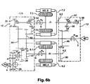
- FIG. 6 schematic representations of a power transmission device Ravigneaux trains and its equivalents according to the invention.
- the figures 2 show on the left kinematic representations of power transmission devices according to the state of the single-mode type of technology that have a single possible configuration of transmission, ie a single mode of operation.
- the figures 2 show kinematic representations of equivalent transmission devices according to the invention in which the epicyclic gear trains have been replaced by an electric machine with rotating stator and a gear ratio.
- FIG. 2a shows on the left a coupled output architecture in which the shafts of the electrical machines 6, 7 (with fixed stator) are respectively connected to the epicyclic gear train 14.1 and the output shaft 4.
- This architecture is called coupled output because the speed of the machine 7 is directly proportional to the speed of the output shaft 4.
- the figure 2b shows on the left a conventional architecture with coupled input in which the shafts of the electrical machines 6 and 7 (fixed stator) are respectively connected to the epicyclic gear 14.1 and the input shaft 2.
- This architecture is called coupled input because the The speed of the machine 7 is directly proportional to the speed of the output shaft 4.
- the Figure 2c shows on the left a combined type architecture in which the electrical machines 6 and 7 (with fixed stator) are connected to the input shaft 2 and to the output shaft 4 each via an epicyclic gear train 14.1, 14.2.
- This architecture is said to be of the combined type because the speed of the machines 6, 7 depends on the regimes of the input and output shafts 4.
- the figures 3 thus show kinematic diagrams of multimode transmissions according to the state of the art, in which the two electric machines 6, 7 with fixed stator are interconnected via two epicyclic gear trains 14.1, 14.2. While the figures 4 show transmission patterns according to the invention equivalent to those of figures 3 in which the planetary gear trains have been replaced by machines 6, 7 with stator and rotor and gear ratios connected in parallel.
- the figure 3a shows a kinematic diagram of a transmission according to the state of the art capable of operating in a coupled output type mode and a combined mode.
- the machine 7, shown in solid lines is connected directly to the output shaft 4, whereas in the combined mode the machine 7, shown in broken lines, is connected to the epicyclic gear train 14.1.
- the figure 4a represents a kinematic diagram of a transmission according to the invention, equivalent, wherein the planetary gear trains 14.1, 14.2 have been replaced by two machines 6, 7 rotating rotor and stator and gear ratios 16.1, 16.2.
- the stator of the machine 7 shown in broken lines is connected to the housing, a gear 16.1a being connected at the output of the machine 7.
- the stator of the machine 7, shown in solid lines is connected to the input shaft 2, a reduction 16.1 b (other than 16.1a) being connected to the output of the machine 7.
- a switching device mounted on the shaft of the machine 7 provides switching from one mode to another.
- the figure 3b shows a kinematic diagram of a transmission according to the state of the art operating in a coupled input type mode and a combined mode.
- the machine 6 shown in broken lines is connected directly to the input shaft 2.
- the machine 6 shown in solid lines is connected to the epicyclic gear train 14.2.
- the figure 4b shows a kinematic diagram of a transmission according to the invention, equivalent, in which the planetary gear trains 14.1, 14.2 have been replaced by two rotating rotor and stator machines 6, 7 and gear ratios 16.1, 16.2.
- the stator of the machine 7 shown in broken lines, is connected to the housing, a gear 16.1a being connected to the output of the machine 7.
- the stator of the machine 7, shown in solid lines is connected to the output shaft 4, a gear 16.1b (other than 16.1a) being connected at the output of the machine 7.
- a switching device mounted on the shaft the machine 7 provides the switching of one mode to another.
- the figure 4c shows a kinematic diagram of a transmission according to the invention with coupled input and output.
- the stator and the rotor of the machine 7 shown in broken lines, are respectively connected to the housing and the input shaft 2, a gear 16.1a being connected at the output of the machine 7.
- the stator and the rotor of the machine 7 are respectively connected to the housing and to the output shaft 4, a gear ratio 16.1b (other than 16.1a) being connected at the output of the machine 7.
- a switching device mounted on the shaft of the machine 7 switches from one mode to the other.
- the figures 5 show transmission patterns according to the invention equivalent to those of the Figures 3 allowing to preserve the property of synchronism of the transmission. For this purpose, replace the epicyclic gear linked to the machine from which no mechanical reconfiguration is performed and the planetary gear train is maintained linked to the machine ensuring the change of mode.
- the figure 5a shows a kinematic diagram of an architecture equivalent to that of the figure 3a in which the planetary gear train 14.2 linked to the machine 6 does not ensure any change of mode is replaced by a rotating rotor and stator machine and a gear ratio 16.2. However the train 14.1 linked to the machine 7 ensuring the change of mode is retained.
- the figure 5b shows a kinematic diagram of an architecture equivalent to that of the figure 3b in which the train 14.2 linked to the machine 6, which is not reconfigured, is replaced by a machine 6 with rotating rotor and stator. However, the train 14.1 linked to the machine 7 allowing the mechanical synchronization during the change of mode is retained.
- the figure 6a shows a schematic representation of a transmission device according to the state of the art comprising a train Ravigneaux (resulting from the combination of two planetary gear trains).
- the figures 6b and 6c respectively show equivalent transmissions according to the invention without Ravigneaux train or with a single epicyclic train.
- the realization without train Ravigneaux implements two electric machines with stator and rotating rotor, whereas the realization with a single epicyclic train implements a conventional electric machine (with fixed stator) and an electric machine with stator and rotating rotor.
- FIG. 6a shows a schematic representation of a conventional transmission device 1 comprising an input shaft 2 intended to be connected to a thermal motor 3 and an output shaft 4 intended to be connected to the wheels 5.
- This device 1 comprises a first electric machine 6 and a second electric machine 7 respectively provided with a shaft 8 and a shaft 9.
- the electrical chain connecting the machines 6 and 7 electric between them is not represented.
- the input and output shafts 2, 4 and the shafts 8 and 9 are interconnected via a mechanical assembly 12 delimited by a discontinuous closed line.
- This mechanical assembly 12 comprises a Ravigneaux-type train resulting from the combination of two trains 14.1 and 14.2 epicyclic.
- the train 14.1, reason R2 comprises a sun gear 17, a planet carrier 19 carrying the satellites 19.1 and a ring 20 which mesh mutually.
- the train 14.2, reason R1 comprises a sun gear 23 and satellites 24 carried by the planet carrier 19. The satellites 24 meshes with the sun gear 23 and the satellites 19.1.
- the train 14. 2 is devoid of crown.
- the input shaft 2 is connected to the planet carrier 19 common to the two trains.
- the output shaft 4 is connected to the ring gear 20 via a bridge drop 25 of ratio ⁇ 1 and a wheel 26.
- the reduction ratio between the ring gear and the wheel 26 is denoted ⁇ 0.
- the shaft 8 is connected to the sun gear 23 via the wheels 29.1 and 29. 2 which form between them a gear 29 of report of gear ratio r1.
- the shaft 9 of the machine 7 may be selectively connected to either the ring 20 or the first sun gear 17 via a wheel 17.1.
- the device 1 comprises a dog clutch C2 which can be associated with an idler gear 31 and a dog clutch C3 that can be associated with an idle gear wheel 32.
- the dogs C2, C3 are rotated by the shaft 9 and are able to move about translation to ensure an angular connection between the shaft 9 and the idler 31,32.
- the idle gear 31 and the ring gear 20 form a reduction ratio gear r2.
- the idler gear 32 and the wheel 17.1 form a reduction ratio gear r3.
- the speed Wa of the machine 6 depends on the engine speeds Wmth and Wsort wheels.
- the speed Wb of the machine 7 is proportional to the speed Wsort of the wheels.
- the dog clutch C3 cooperates with the pinion 32. While the clutch C2 is disengaged from the pinion 31 and therefore does not transmit mechanical torque.
- the mode change is performed when the shaft 9 and the pinions 31 and 32 have substantially the same speed of rotation.
- a transmission device 1.1 represented in FIG. figure 6b .
- This device 1.1 devoid of epicyclic trains corresponds to the realization of the figure 4a .
- the sizing of the electrical machines 6, 7 is identical to that of the transmission of the figure 6a .
- the ratios ⁇ 0, ⁇ 1, r2 as well as the positioning of the shafts 8, 9 and claws C2, C3 are retained.
- the device 1.1 comprises a first electrical machine 6 provided with a rotor 6.1 and a stator 6.2 rotating and a second electric machine 7 provided with a rotor 7.1 and a stator 7.2 rotating.
- the input shafts 2 and 4 as well as the shafts of the electrical machines 6, 7 are interconnected by means of a mechanical assembly 12 formed by a plurality of single gear wheels.
- the output shaft 4 is connected to a tree intermediate 4.1 via a bridge descent 25 report ⁇ 1, this intermediate shaft 4.1 itself being connected to the input shaft 2 via a gear ratio ⁇ 0 formed by the wheels 44 and 26.
- the reports ⁇ 0 and ⁇ 1 are identical to those of the figure 6a .
- the shaft 8 of the rotor of the machine 6 is connected to the wheel 45 via a wheel 47, the gear ratio between these two wheels being noted q1.
- the shaft 8.2 of the stator of the machine 6 is connected to the input shaft 2 via a ratio gear q2 formed by the wheels 49 and 50.
- the shaft 9 of the rotor of the machine 7 can be selectively connected to the shaft 2 via a gear ratio r2 formed by the wheels 31 and 44 or via a gear q3 ratio formed by the wheels 32, 53 and 45.
- the device 1 comprises a dog clutch C2 associated with the idler gear 31 and a clutch C3 associated with the idler gear 32.
- the shaft 9.2 of the stator 7.2 of the machine 7 can be selectively connected to the housing 55 or to the input shaft 2 via a ratio gear q4 formed by the idler gear 57 and the wheels 49 and 58.
- the device 1 comprises a clutch C5 associable with the frame 55 and a Clutch C4 associated with the idle gear 57.
- the regime Wa of the rotor 6.1 of the machine 6 depends on the speed of the input and output shafts 4; and the speed Wb of the rotor 7.1 the machine 7 is proportional to that of the output shaft 4 (vehicle wheels).
- the coupled output mode observable during the mode change with C3 and C5 engaged and C2, C4 disengaged could be used independently of other modes in particular vehicle life phases such as take-offs (phases in which the vehicle goes from zero speed to non-zero speed), or hill starts.
- the dimensioning of the electrical machines 6, 7 is identical to that of the transmission represented in FIG. figure 6a .
- the multiplications ⁇ 0, ⁇ 1, r2 and r3 as well as the positioning of the shafts 2, 4, 8 and 9 and jaws C2, C3 are retained.
- the device 1.1 comprises a first electrical machine 6 provided with a rotating rotor 6.1 and a stator 6.2 as well as a second electric machine 7 with a rotating rotor 7.1 and a fixed stator 7.2.
- the input shafts 2 and 4 as well as the shafts of the machines 6, 7 are interconnected by means of a mechanical assembly 12 formed by the epicyclic gear train 14.1.
- This train 14. 1 comprises a sun gear 17, a planet carrier 19 carrying the satellites 19.1 and a ring 20 which mesh mutually.
- the input shaft 2 is connected to the sun gear 19.
- the output shaft 4 is connected to an intermediate shaft 4.1 via the bridge descent 25 of report ⁇ 1.
- This intermediate shaft 4.1 is itself connected to the ring 20 via a wheel 26.
- the ring 20 and the wheel 26 have between them a gear ratio ⁇ 0.
- the ratios ⁇ 0 and ⁇ 1 are identical to those of the figure 6a .
- the shaft 8 of the rotor of the machine 6 is connected to the sun gear 17 via a ratio gear q1 formed by the wheels 45 and 47.
- the shaft 8.2 of the stator of the machine 6 is connected to the shaft 2 d input via a ratio gear q2 formed by the wheels 49 and 50.
- the shaft 9 of the rotor of the machine 7 can be selectively connected to the shaft 2 via a gear ratio r2 formed by the wheels 31 and 44 or via a gear q3 ratio formed by the wheels 32, 53 and 45.
- the device 1 comprises a dog clutch C2 associated with the idler gear 31 and a clutch C3 associated with the idler gear 32.
- the shaft 9 of the machine 7 is capable of being selectively connected either to the ring gear 20 or to the first sun gear 17.
- the device 1 comprises a clutch C2 that can be associated with an idle gear 31 and a clutch C3 that can be associated with a crazy gear 32.
- the idle gear 31 and the ring gear 20 form a reduction ratio gear r2.
- the idler gear 32 and the wheel 45 form a reduction ratio gear r3.
- the rotor scheme Wa 6.1 of machine 6 depends on the speed of the input and output shafts 2; and the speed Wb of the machine 7 is proportional to that of the output shaft 4 (of the vehicle wheels).
- the mode change is performed when the shaft 9 and the pinions 31 and 32 have substantially the same speed of rotation.
- the displacement of the claws is carried out in a conventional manner using forks.
Landscapes
- Engineering & Computer Science (AREA)
- Mechanical Engineering (AREA)
- Chemical & Material Sciences (AREA)
- Combustion & Propulsion (AREA)
- Transportation (AREA)
- General Engineering & Computer Science (AREA)
- Structure Of Transmissions (AREA)
Claims (14)
- Vorrichtung (1.1) zur Leistungsübertragung, die eine Eingangswelle (2) aufweist, die dazu bestimmt ist, mit einem Verbrennungsmotor (3) verbunden zu werden, und eine Ausgangswelle (4), die dazu bestimmt ist, mit einer Radwelle (5) verbunden zu werden, wobei diese Vorrichtung (1.1) ferner Folgendes aufweist:- eine erste und eine zweite elektrische Maschine (6, 7), die jeweils einen Stator (6.2, 7.2) und einen Rotor (6.1, 7.1) aufweisen, wobei jede Maschine (6, 7) jeweils mit einer Welle (8, 9) versehen ist, und- eine mechanische Baugruppe (12), die die mechanische Verbindung zwischen der Eingangswelle (2), der Ausgangswelle (4) und den Wellen (8, 9) der Maschinen (6, 7) sicherstellt,- wobei mindestens eine der elektrischen Maschinen (6, 7) einen drehenden Rotor (6.1) und einen drehenden Stator (6.2) aufweist, die mit der mechanischen Baugruppe (12) verbunden sind, und wobei die Vorrichtung ferner Folgendes aufweist- eine Umschaltvorrichtung (C2, C3, C4, C5), die auf die Welle einer der elektrischen Maschinen montiert ist, wobei es diese Umschaltvorrichtung (C2, C3, C4, C5) erlaubt, selektiv die Welle (8, 9) der Maschine (6, 7) mit zwei unterschiedlichen Elementen der mechanischen Baugruppe (12) zu verbinden, um einen Wechsel der Betriebsart der Leistungsübertragungsvorrichtung sicherzustellen,dadurch gekennzeichnet, dass:- die Drehzahl der elektrischen Maschine (6, 7), die die Umschaltvorrichtung trägt, ausschließlich zu der Drehzahl der Räder (5) oder des Motors (3) proportional ist, wenn die Welle der Maschine (6, 7) mit einem der zwei Elemente der mechanischen Baugruppe (12) verbunden ist, und- die Drehzahl der elektrischen Maschine (6, 7), die die Umschaltvorrichtung trägt, von der Drehzahl der Räder (5) und des Motors (3) abhängt, wenn die Welle der Maschine (6, 7) mit einem anderen Element der mechanischen Baugruppe (12) verbunden ist.
- Vorrichtung nach Anspruch 1, dadurch gekennzeichnet, dass, da die zwei elektrischen Maschinen (6, 7) einen drehenden Stator haben, die mechanische Baugruppe (12) keinen Planetengetriebezug aufweist.
- Vorrichtung nach Anspruch 1, dadurch gekennzeichnet, dass, da eine der Maschinen (6) einen drehenden Stator hat und die andere (7) einen stationären Stator, die mechanische Baugruppe (12) nur einen Planetengetriebezug (14.1) aufweist, der von einem Zentralrad (17), einem Planetenradträger (19), der Satellitenräder (19.1) trägt, und aus einem Zahnkranz (20), die untereinander eingreifen, ausgebildet ist.
- Vorrichtung nach Anspruch 3, dadurch gekennzeichnet, dass die Eingangswelle (2) direkt mit dem Planetenradträger (19) verbunden ist, und die Ausgangswelle (4) mit einer Zwischenwelle (4.1) über eine Brückenabsenkung (25) mit dem Verhältnis µ1 verbunden ist, wobei diese Zwischenwelle (4.1) mit dem Zahnkranz (20) über ein Radgetriebe mit dem Verhältnis µ0 verbunden ist.
- Vorrichtung nach Anspruch 3 oder 4, dadurch gekennzeichnet, dass die Welle (9) der Maschine (7) mit stationärem Stator selektiv mit dem Zahnkranz (20) über ein Radgetriebe mit dem Verhältnis r2 oder mit dem Zentralrad (17) über ein Radgetriebe mit dem Verhältnis r3 verbunden werden kann.
- Vorrichtung nach einem der Ansprüche 3 bis 5, dadurch gekennzeichnet, dass der Stator (6.2) der Maschine (6) mit drehendem Stator mit der Eingangswelle (2) über ein Radgetriebe mit dem Verhältnis q2 und der Rotor (6.1) der Maschine mit drehendem Stator mit dem Zentralrad (17) über ein Radgetriebe mit dem Verhältnis q1 verbunden ist.
- Vorrichtung nach den Ansprüchen 4, 5 und 6, dadurch gekennzeichnet, dass µ0= -0,15; µ1 = -1,65; r2 = 0,25; r3 = -0,89; q1 = -0,26; q2 = -0,50.
- Vorrichtung nach Anspruch 2, dadurch gekennzeichnet, dass die Ausgangswelle (4) mit einer Zwischenwelle (4.1) über eine Brückenabsenkung (25) mit dem Verhältnis µ1 verbunden ist, wobei diese Zwischenwelle (4.1) selbst mit der Eingangswelle (2) über ein Radgetriebe mit dem Verhältnis µ0 verbunden ist.
- Vorrichtung nach Anspruch 2 oder 8, dadurch gekennzeichnet, dass der Rotor der ersten Maschine (6) mit den Rädern (5) über ein Radgetriebe mit dem Verhältnis q1 verbunden ist, und dass der Stator dieser Maschine (6) mit der Eingangswelle (2) über ein Radgetriebe mit dem Verhältnis q2 verbunden ist.
- Vorrichtung nach einem der Ansprüche 2, 8 oder 9, dadurch gekennzeichnet, dass der Rotor der zweiten Maschine (7) selektiv mit der Ausgangswelle (4) über ein Radgetriebe mit dem Verhältnis r2 oder über eine Radgetriebe mit dem Verhältnis q3 jeweils mittels einer ersten Klaue (C2) und einer zweiten Klaue (C3) verbunden werden kann, und- dass der Stator dieser zweiten Maschine (7) selektiv mit der Eingangswelle (2) über ein Radgetriebe mit dem Verhältnis q4 oder mit dem stationären Rahmen (55) jeweils mittels einer dritten Klaue (C4) und einer vierten Klaue (C5) verbunden werden kann.
- Vorrichtung nach den Ansprüchen 2, 8, 9 und 10, dadurch gekennzeichnet, dass µ0 = -0,15; µ1 = -1,65; r2 = 0,25; r3 = -0,89; q1 = -0,26; q2 = -0,50; q3 = 0,49; q4 = 0,32.
- Gebrauch einer Vorrichtung nach Anspruch 10, dadurch gekennzeichnet, dass:- man bei einer Betriebsart des Typs gekoppelter Ausgang die erste (C2) und vierte (C5) Klaue schließt und die zweite (C3) und dritte (C4) Klaue öffnet, und- man bei einer kombinierten Betriebsart die zweite (C3) und dritte (C4) Klaue schließt und man die erste (C2) und die vierte (C5) Klaue öffnet.
- Gebrauch nach Anspruch 12, dadurch gekennzeichnet, dass man, um von der Betriebsart mit gekoppeltem Ausgang zu der kombinierten Betriebsart überzugehen, die erste Klaue (C2) ausrückt und gleichzeitig die vierte Klaue (C5) eingerückt lässt, man die Drehzahl des Rotors der zweiten Maschine (7) mit einem Freilaufrad (32), das der zweiten Klaue (C3) zugewiesen werden kann, synchronisiert, dass dann man diese zweite Klaue (C3) einrückt und die vierte Klaue (C5) ausrückt, man die Drehzahl des Stators der Maschine (7) mit dem der Klaue (C4) zuweisbaren Ritzel (57) synchronisiert, und man die Klaue (C4) mit diesem Ritzel (57) einrückt.
- Gebrauch nach Anspruch 12 oder 13, dadurch gekennzeichnet, dass man zum Übergehen von der kombinierten Betriebsart auf die Betriebsart mit gekoppeltem Ausgang die dritte Klaue (C4) ausrückt und den Stator der zweiten Maschine (7) derart stoppt, dass die vierte Klaue (C5) mit dem Ritzel (55), zu dem sie gehört, einrückt, und man die zweite Klaue (C3) öffnet und den Rotor der zweiten Maschine (7) mit dem Ritzel (31), das der ersten Klaue (C2) zugewiesen werden kann, synchronisiert und man die erste Klaue (C2) mit diesem Ritzel (31) einrückt.
Applications Claiming Priority (2)
| Application Number | Priority Date | Filing Date | Title |
|---|---|---|---|
| FR0758834A FR2923185B1 (fr) | 2007-11-07 | 2007-11-07 | Dispositif de transmission de puissance entre une sortie d'un moteur thermique et un arbre de roues et utilisation de ce dispositif |
| PCT/FR2008/052012 WO2009068796A1 (fr) | 2007-11-07 | 2008-11-07 | Dispositif de transmission de puissance entre une sortie d'un moteur thermique et un arbre de roues et utilisation de ce dispositif |
Publications (2)
| Publication Number | Publication Date |
|---|---|
| EP2209660A1 EP2209660A1 (de) | 2010-07-28 |
| EP2209660B1 true EP2209660B1 (de) | 2012-10-10 |
Family
ID=39432974
Family Applications (1)
| Application Number | Title | Priority Date | Filing Date |
|---|---|---|---|
| EP08855726A Not-in-force EP2209660B1 (de) | 2007-11-07 | 2008-11-07 | Vorrichtung zur leistungsübertragung zwischen dem ausgang eines wärmemotors und einer radachse sowie verwendung dieser vorrichtung |
Country Status (5)
| Country | Link |
|---|---|
| US (1) | US8287413B2 (de) |
| EP (1) | EP2209660B1 (de) |
| FR (1) | FR2923185B1 (de) |
| RU (1) | RU2484984C2 (de) |
| WO (1) | WO2009068796A1 (de) |
Families Citing this family (9)
| Publication number | Priority date | Publication date | Assignee | Title |
|---|---|---|---|---|
| GB2466975B (en) * | 2009-01-16 | 2013-06-19 | Gm Global Tech Operations Inc | Torque distributing drive mechanism for motorized vehicles |
| WO2011139186A1 (en) * | 2010-05-06 | 2011-11-10 | Volvo Construction Equipment Ab | A continuously variable transmission and a working machine |
| WO2017111862A1 (en) * | 2015-12-23 | 2017-06-29 | Xiaolin Ai | Multimode electromechanical variable speed transmission apparatus with smooth mode shifting and method of controlling the same |
| FR3048047B1 (fr) * | 2016-02-19 | 2018-03-09 | Renault S.A.S | Procede de controle du decrabotage d'un baladeur |
| WO2018019612A1 (de) * | 2016-07-26 | 2018-02-01 | Voith Patent Gmbh | Antriebsvorrichtung mit überlagerungsgetriebe |
| US12553379B2 (en) * | 2016-12-14 | 2026-02-17 | Bendix Commercial Vehicle Systems Llc | Front end motor-generator system and hybrid electric vehicle operating method |
| US10308104B2 (en) * | 2017-01-13 | 2019-06-04 | Ford Global Technologies, Llc | HyBrid transaxle |
| DE202018100711U1 (de) * | 2018-02-09 | 2018-02-15 | Voith Patent Gmbh | Antriebsvorrichtung mit Drehzahllimitierung |
| US10744865B2 (en) | 2018-10-09 | 2020-08-18 | Ford Global Technologies, Llc | Hybrid transaxle |
Family Cites Families (13)
| Publication number | Priority date | Publication date | Assignee | Title |
|---|---|---|---|---|
| PL196829B1 (pl) * | 1998-03-27 | 2008-02-29 | Bosch Gmbh Robert | Układ napędowy dla samochodu |
| JP3412544B2 (ja) | 1999-02-04 | 2003-06-03 | トヨタ自動車株式会社 | 動力出力装置およびその制御方法 |
| FR2799418B1 (fr) * | 1999-10-11 | 2001-12-14 | Renault | Groupe motopropulseur d'un vehicule hybride a coupleur electromagnetique |
| US6656082B1 (en) | 1999-10-12 | 2003-12-02 | Toyota Jidosha Kabushiki Kaisha | Hybrid vehicle and method of controlling the same |
| DE10146386A1 (de) * | 2001-09-20 | 2003-04-17 | Gkn Automotive Gmbh | Antriebseinheit |
| FR2832357B1 (fr) | 2001-11-21 | 2004-02-27 | Peugeot Citroen Automobiles Sa | Dispositif de transmission de puissance a au moins deux trains epicycloidaux |
| FR2834248B1 (fr) * | 2001-12-28 | 2005-06-24 | Renault | Dispositif de traction hybride parallele, et procedes de commande de ce dispositif |
| FR2834938B1 (fr) * | 2002-01-23 | 2004-06-04 | Renault | Groupe motopropulseur pour vehicule a transmission electrique hybride |
| RU2264307C2 (ru) * | 2003-10-01 | 2005-11-20 | Никишин Сергей Владимирович | Гибридный силовой агрегат |
| FR2883515B1 (fr) | 2005-03-23 | 2008-10-31 | Peugeot Citroen Automobiles Sa | Dispositif de transmission de puissance entre une sortie d'un moteur thermique et un arbre de roues et procede de transmission de puissance associe |
| US7479081B2 (en) * | 2006-10-25 | 2009-01-20 | Gm Global Technology Operations | Hybrid electrically variable transmission with dual power paths and selective motor connection |
| ITMI20070528A1 (it) * | 2007-03-16 | 2008-09-17 | Piaggio & C Spa | Sistema di propulsione e di trasmissione ibrida per motoveicoli |
| US7980980B2 (en) * | 2007-11-14 | 2011-07-19 | GM Global Technology Operations LLC | Hybrid powertrain |
-
2007
- 2007-11-07 FR FR0758834A patent/FR2923185B1/fr not_active Expired - Fee Related
-
2008
- 2008-11-07 RU RU2010123019/11A patent/RU2484984C2/ru not_active IP Right Cessation
- 2008-11-07 EP EP08855726A patent/EP2209660B1/de not_active Not-in-force
- 2008-11-07 US US12/738,981 patent/US8287413B2/en not_active Expired - Fee Related
- 2008-11-07 WO PCT/FR2008/052012 patent/WO2009068796A1/fr not_active Ceased
Also Published As
| Publication number | Publication date |
|---|---|
| RU2010123019A (ru) | 2011-12-20 |
| RU2484984C2 (ru) | 2013-06-20 |
| EP2209660A1 (de) | 2010-07-28 |
| FR2923185B1 (fr) | 2010-04-02 |
| US8287413B2 (en) | 2012-10-16 |
| FR2923185A1 (fr) | 2009-05-08 |
| WO2009068796A1 (fr) | 2009-06-04 |
| US20100320017A1 (en) | 2010-12-23 |
Similar Documents
| Publication | Publication Date | Title |
|---|---|---|
| EP1453694B1 (de) | Kraftübertragungsvorrichtung mit mindestens zwei planetengetriebezügen | |
| EP2694309B1 (de) | Hybridgetriebe für ein kraftfahrzeug und steuerverfahren | |
| EP2209660A1 (de) | Vorrichtung zur leistungsübertragung zwischen dem ausgang eines wärmemotors und einer radachse sowie verwendung dieser vorrichtung | |
| EP1877273B1 (de) | Schaltvorrichtung für ein kraftfahrzeug und ihre verwendung | |
| EP2001719B1 (de) | Kraftübertragungsverfahren | |
| WO2016092184A1 (fr) | Transmission automatique pour véhicule hybride et procédé de commande d'un véhicule hybride | |
| FR2835301A1 (fr) | Boite de vitesses a arbre intermediaire pour vehicules automobiles | |
| FR2976526A1 (fr) | Groupe motopropulseur | |
| WO2006125876A1 (fr) | Boite de vitesses a double embrayage | |
| FR3100755A1 (fr) | Chaîne de transmission électrique pour véhicule automobile | |
| WO2015181480A1 (fr) | Transmission automatique pour vehicule hybride et procédé de commande | |
| WO2012042137A1 (fr) | Groupe motopropulseur hybride a arbres d'entree coaxiaux et procede de commande correspondant | |
| EP1916141B1 (de) | Antriebssystem für Hybridfahrzeuge | |
| EP1092583A1 (de) | Antriebseinheit eines Hybridfahrzeugs mit elektromagnetischem Koppler | |
| FR2946293A1 (fr) | Groupe motopropulseur pour vehicule electrique a trois arbres permettant d'obtenir deux rapports de transmission | |
| WO2011055050A1 (fr) | Groupe motopropulseur hybride multirapports a deux machines electriques | |
| EP1627163A1 (de) | Doppelkupplungsgetriebe mit zwei vorgelegewellen | |
| EP1789722B1 (de) | Antriebseinheit für ein hybridfahrzeug und verfahren | |
| FR3106089A1 (fr) | Transmission automatique pour véhicule hybride thermique/électrique | |
| EP3699008A1 (de) | Hybridantriebsvorrichtung eines kraftfahrzeugs, und leistungsübertragungsmechanismus | |
| FR3077536A1 (fr) | Dispositif de transmission a deux vitesses pour vehicule electrique | |
| FR3098766A1 (fr) | Transmission automatique pour véhicule hybride thermique/électrique | |
| FR2967620A1 (fr) | Vehicule hybride a deux trains d'engrenages epicycloidaux a derivation de puissance et a efficacite energetique amelioree | |
| FR3106090A1 (fr) | Transmission pour véhicule hybride et son procédé de commande | |
| WO2025219107A1 (fr) | Systeme de transmission automatique de vitesse pour un vehicule comportant une machine electrique |
Legal Events
| Date | Code | Title | Description |
|---|---|---|---|
| PUAI | Public reference made under article 153(3) epc to a published international application that has entered the european phase |
Free format text: ORIGINAL CODE: 0009012 |
|
| 17P | Request for examination filed |
Effective date: 20100319 |
|
| AK | Designated contracting states |
Kind code of ref document: A1 Designated state(s): AT BE BG CH CY CZ DE DK EE ES FI FR GB GR HR HU IE IS IT LI LT LU LV MC MT NL NO PL PT RO SE SI SK TR |
|
| AX | Request for extension of the european patent |
Extension state: AL BA MK RS |
|
| DAX | Request for extension of the european patent (deleted) | ||
| 17Q | First examination report despatched |
Effective date: 20110708 |
|
| GRAP | Despatch of communication of intention to grant a patent |
Free format text: ORIGINAL CODE: EPIDOSNIGR1 |
|
| GRAS | Grant fee paid |
Free format text: ORIGINAL CODE: EPIDOSNIGR3 |
|
| GRAA | (expected) grant |
Free format text: ORIGINAL CODE: 0009210 |
|
| AK | Designated contracting states |
Kind code of ref document: B1 Designated state(s): AT BE BG CH CY CZ DE DK EE ES FI FR GB GR HR HU IE IS IT LI LT LU LV MC MT NL NO PL PT RO SE SI SK TR |
|
| REG | Reference to a national code |
Ref country code: GB Ref legal event code: FG4D Free format text: NOT ENGLISH |
|
| REG | Reference to a national code |
Ref country code: AT Ref legal event code: REF Ref document number: 578782 Country of ref document: AT Kind code of ref document: T Effective date: 20121015 Ref country code: CH Ref legal event code: EP |
|
| REG | Reference to a national code |
Ref country code: IE Ref legal event code: FG4D Free format text: LANGUAGE OF EP DOCUMENT: FRENCH |
|
| REG | Reference to a national code |
Ref country code: DE Ref legal event code: R096 Ref document number: 602008019341 Country of ref document: DE Effective date: 20121206 |
|
| PG25 | Lapsed in a contracting state [announced via postgrant information from national office to epo] |
Ref country code: SI Free format text: LAPSE BECAUSE OF FAILURE TO SUBMIT A TRANSLATION OF THE DESCRIPTION OR TO PAY THE FEE WITHIN THE PRESCRIBED TIME-LIMIT Effective date: 20121010 |
|
| REG | Reference to a national code |
Ref country code: GB Ref legal event code: 746 Effective date: 20130215 Ref country code: NL Ref legal event code: VDEP Effective date: 20121010 |
|
| REG | Reference to a national code |
Ref country code: AT Ref legal event code: MK05 Ref document number: 578782 Country of ref document: AT Kind code of ref document: T Effective date: 20121010 |
|
| REG | Reference to a national code |
Ref country code: LT Ref legal event code: MG4D |
|
| REG | Reference to a national code |
Ref country code: DE Ref legal event code: R084 Ref document number: 602008019341 Country of ref document: DE Effective date: 20130206 |
|
| PG25 | Lapsed in a contracting state [announced via postgrant information from national office to epo] |
Ref country code: SE Free format text: LAPSE BECAUSE OF FAILURE TO SUBMIT A TRANSLATION OF THE DESCRIPTION OR TO PAY THE FEE WITHIN THE PRESCRIBED TIME-LIMIT Effective date: 20121010 Ref country code: IS Free format text: LAPSE BECAUSE OF FAILURE TO SUBMIT A TRANSLATION OF THE DESCRIPTION OR TO PAY THE FEE WITHIN THE PRESCRIBED TIME-LIMIT Effective date: 20130210 Ref country code: FI Free format text: LAPSE BECAUSE OF FAILURE TO SUBMIT A TRANSLATION OF THE DESCRIPTION OR TO PAY THE FEE WITHIN THE PRESCRIBED TIME-LIMIT Effective date: 20121010 Ref country code: ES Free format text: LAPSE BECAUSE OF FAILURE TO SUBMIT A TRANSLATION OF THE DESCRIPTION OR TO PAY THE FEE WITHIN THE PRESCRIBED TIME-LIMIT Effective date: 20130121 Ref country code: HR Free format text: LAPSE BECAUSE OF FAILURE TO SUBMIT A TRANSLATION OF THE DESCRIPTION OR TO PAY THE FEE WITHIN THE PRESCRIBED TIME-LIMIT Effective date: 20121010 Ref country code: NL Free format text: LAPSE BECAUSE OF FAILURE TO SUBMIT A TRANSLATION OF THE DESCRIPTION OR TO PAY THE FEE WITHIN THE PRESCRIBED TIME-LIMIT Effective date: 20121010 Ref country code: LT Free format text: LAPSE BECAUSE OF FAILURE TO SUBMIT A TRANSLATION OF THE DESCRIPTION OR TO PAY THE FEE WITHIN THE PRESCRIBED TIME-LIMIT Effective date: 20121010 Ref country code: NO Free format text: LAPSE BECAUSE OF FAILURE TO SUBMIT A TRANSLATION OF THE DESCRIPTION OR TO PAY THE FEE WITHIN THE PRESCRIBED TIME-LIMIT Effective date: 20130110 |
|
| BERE | Be: lapsed |
Owner name: PEUGEOT CITROEN AUTOMOBILES SA Effective date: 20121130 |
|
| PG25 | Lapsed in a contracting state [announced via postgrant information from national office to epo] |
Ref country code: PL Free format text: LAPSE BECAUSE OF FAILURE TO SUBMIT A TRANSLATION OF THE DESCRIPTION OR TO PAY THE FEE WITHIN THE PRESCRIBED TIME-LIMIT Effective date: 20121010 Ref country code: LV Free format text: LAPSE BECAUSE OF FAILURE TO SUBMIT A TRANSLATION OF THE DESCRIPTION OR TO PAY THE FEE WITHIN THE PRESCRIBED TIME-LIMIT Effective date: 20121010 Ref country code: GR Free format text: LAPSE BECAUSE OF FAILURE TO SUBMIT A TRANSLATION OF THE DESCRIPTION OR TO PAY THE FEE WITHIN THE PRESCRIBED TIME-LIMIT Effective date: 20130111 Ref country code: PT Free format text: LAPSE BECAUSE OF FAILURE TO SUBMIT A TRANSLATION OF THE DESCRIPTION OR TO PAY THE FEE WITHIN THE PRESCRIBED TIME-LIMIT Effective date: 20130211 |
|
| PG25 | Lapsed in a contracting state [announced via postgrant information from national office to epo] |
Ref country code: AT Free format text: LAPSE BECAUSE OF FAILURE TO SUBMIT A TRANSLATION OF THE DESCRIPTION OR TO PAY THE FEE WITHIN THE PRESCRIBED TIME-LIMIT Effective date: 20121010 |
|
| REG | Reference to a national code |
Ref country code: CH Ref legal event code: PL |
|
| PG25 | Lapsed in a contracting state [announced via postgrant information from national office to epo] |
Ref country code: BG Free format text: LAPSE BECAUSE OF FAILURE TO SUBMIT A TRANSLATION OF THE DESCRIPTION OR TO PAY THE FEE WITHIN THE PRESCRIBED TIME-LIMIT Effective date: 20130110 Ref country code: SK Free format text: LAPSE BECAUSE OF FAILURE TO SUBMIT A TRANSLATION OF THE DESCRIPTION OR TO PAY THE FEE WITHIN THE PRESCRIBED TIME-LIMIT Effective date: 20121010 Ref country code: LI Free format text: LAPSE BECAUSE OF NON-PAYMENT OF DUE FEES Effective date: 20121130 Ref country code: EE Free format text: LAPSE BECAUSE OF FAILURE TO SUBMIT A TRANSLATION OF THE DESCRIPTION OR TO PAY THE FEE WITHIN THE PRESCRIBED TIME-LIMIT Effective date: 20121010 Ref country code: DK Free format text: LAPSE BECAUSE OF FAILURE TO SUBMIT A TRANSLATION OF THE DESCRIPTION OR TO PAY THE FEE WITHIN THE PRESCRIBED TIME-LIMIT Effective date: 20121010 Ref country code: CZ Free format text: LAPSE BECAUSE OF FAILURE TO SUBMIT A TRANSLATION OF THE DESCRIPTION OR TO PAY THE FEE WITHIN THE PRESCRIBED TIME-LIMIT Effective date: 20121010 Ref country code: CH Free format text: LAPSE BECAUSE OF NON-PAYMENT OF DUE FEES Effective date: 20121130 |
|
| REG | Reference to a national code |
Ref country code: IE Ref legal event code: MM4A |
|
| PLBE | No opposition filed within time limit |
Free format text: ORIGINAL CODE: 0009261 |
|
| STAA | Information on the status of an ep patent application or granted ep patent |
Free format text: STATUS: NO OPPOSITION FILED WITHIN TIME LIMIT |
|
| PG25 | Lapsed in a contracting state [announced via postgrant information from national office to epo] |
Ref country code: RO Free format text: LAPSE BECAUSE OF FAILURE TO SUBMIT A TRANSLATION OF THE DESCRIPTION OR TO PAY THE FEE WITHIN THE PRESCRIBED TIME-LIMIT Effective date: 20121010 Ref country code: BE Free format text: LAPSE BECAUSE OF NON-PAYMENT OF DUE FEES Effective date: 20121130 Ref country code: IT Free format text: LAPSE BECAUSE OF FAILURE TO SUBMIT A TRANSLATION OF THE DESCRIPTION OR TO PAY THE FEE WITHIN THE PRESCRIBED TIME-LIMIT Effective date: 20121010 |
|
| 26N | No opposition filed |
Effective date: 20130711 |
|
| PG25 | Lapsed in a contracting state [announced via postgrant information from national office to epo] |
Ref country code: IE Free format text: LAPSE BECAUSE OF NON-PAYMENT OF DUE FEES Effective date: 20121107 |
|
| REG | Reference to a national code |
Ref country code: DE Ref legal event code: R097 Ref document number: 602008019341 Country of ref document: DE Effective date: 20130711 |
|
| PG25 | Lapsed in a contracting state [announced via postgrant information from national office to epo] |
Ref country code: CY Free format text: LAPSE BECAUSE OF FAILURE TO SUBMIT A TRANSLATION OF THE DESCRIPTION OR TO PAY THE FEE WITHIN THE PRESCRIBED TIME-LIMIT Effective date: 20121010 Ref country code: MT Free format text: LAPSE BECAUSE OF FAILURE TO SUBMIT A TRANSLATION OF THE DESCRIPTION OR TO PAY THE FEE WITHIN THE PRESCRIBED TIME-LIMIT Effective date: 20121010 |
|
| PG25 | Lapsed in a contracting state [announced via postgrant information from national office to epo] |
Ref country code: MC Free format text: LAPSE BECAUSE OF NON-PAYMENT OF DUE FEES Effective date: 20121130 Ref country code: TR Free format text: LAPSE BECAUSE OF FAILURE TO SUBMIT A TRANSLATION OF THE DESCRIPTION OR TO PAY THE FEE WITHIN THE PRESCRIBED TIME-LIMIT Effective date: 20121010 |
|
| PG25 | Lapsed in a contracting state [announced via postgrant information from national office to epo] |
Ref country code: LU Free format text: LAPSE BECAUSE OF NON-PAYMENT OF DUE FEES Effective date: 20121107 |
|
| PG25 | Lapsed in a contracting state [announced via postgrant information from national office to epo] |
Ref country code: HU Free format text: LAPSE BECAUSE OF FAILURE TO SUBMIT A TRANSLATION OF THE DESCRIPTION OR TO PAY THE FEE WITHIN THE PRESCRIBED TIME-LIMIT Effective date: 20081107 |
|
| REG | Reference to a national code |
Ref country code: FR Ref legal event code: PLFP Year of fee payment: 8 |
|
| PGFP | Annual fee paid to national office [announced via postgrant information from national office to epo] |
Ref country code: GB Payment date: 20151027 Year of fee payment: 8 Ref country code: DE Payment date: 20151022 Year of fee payment: 8 |
|
| PGFP | Annual fee paid to national office [announced via postgrant information from national office to epo] |
Ref country code: FR Payment date: 20151023 Year of fee payment: 8 |
|
| REG | Reference to a national code |
Ref country code: DE Ref legal event code: R119 Ref document number: 602008019341 Country of ref document: DE |
|
| GBPC | Gb: european patent ceased through non-payment of renewal fee |
Effective date: 20161107 |
|
| REG | Reference to a national code |
Ref country code: FR Ref legal event code: ST Effective date: 20170731 |
|
| PG25 | Lapsed in a contracting state [announced via postgrant information from national office to epo] |
Ref country code: FR Free format text: LAPSE BECAUSE OF NON-PAYMENT OF DUE FEES Effective date: 20161130 |
|
| PG25 | Lapsed in a contracting state [announced via postgrant information from national office to epo] |
Ref country code: DE Free format text: LAPSE BECAUSE OF NON-PAYMENT OF DUE FEES Effective date: 20170601 Ref country code: GB Free format text: LAPSE BECAUSE OF NON-PAYMENT OF DUE FEES Effective date: 20161107 |