EP2209732B1 - Justierungs- und sperrmechanismus - Google Patents
Justierungs- und sperrmechanismus Download PDFInfo
- Publication number
- EP2209732B1 EP2209732B1 EP08848606.3A EP08848606A EP2209732B1 EP 2209732 B1 EP2209732 B1 EP 2209732B1 EP 08848606 A EP08848606 A EP 08848606A EP 2209732 B1 EP2209732 B1 EP 2209732B1
- Authority
- EP
- European Patent Office
- Prior art keywords
- spindle
- gantry
- drive gear
- drive
- frame
- Prior art date
- Legal status (The legal status is an assumption and is not a legal conclusion. Google has not performed a legal analysis and makes no representation as to the accuracy of the status listed.)
- Not-in-force
Links
- 239000000463 material Substances 0.000 description 2
- XAGFODPZIPBFFR-UHFFFAOYSA-N aluminium Chemical compound [Al] XAGFODPZIPBFFR-UHFFFAOYSA-N 0.000 description 1
- 229910052782 aluminium Inorganic materials 0.000 description 1
- 239000004411 aluminium Substances 0.000 description 1
- 230000000881 depressing effect Effects 0.000 description 1
- 230000000994 depressogenic effect Effects 0.000 description 1
- 238000001125 extrusion Methods 0.000 description 1
- 239000004519 grease Substances 0.000 description 1
- 238000004519 manufacturing process Methods 0.000 description 1
- 125000006850 spacer group Chemical group 0.000 description 1
- 238000005728 strengthening Methods 0.000 description 1
Images

Classifications
-
- B—PERFORMING OPERATIONS; TRANSPORTING
- B66—HOISTING; LIFTING; HAULING
- B66C—CRANES; LOAD-ENGAGING ELEMENTS OR DEVICES FOR CRANES, CAPSTANS, WINCHES, OR TACKLES
- B66C19/00—Cranes comprising trolleys or crabs running on fixed or movable bridges or gantries
- B66C19/02—Cranes comprising trolleys or crabs running on fixed or movable bridges or gantries collapsible
-
- B—PERFORMING OPERATIONS; TRANSPORTING
- B66—HOISTING; LIFTING; HAULING
- B66C—CRANES; LOAD-ENGAGING ELEMENTS OR DEVICES FOR CRANES, CAPSTANS, WINCHES, OR TACKLES
- B66C15/00—Safety gear
-
- B—PERFORMING OPERATIONS; TRANSPORTING
- B66—HOISTING; LIFTING; HAULING
- B66D—CAPSTANS; WINCHES; TACKLES, e.g. PULLEY BLOCKS; HOISTS
- B66D1/00—Rope, cable, or chain winding mechanisms; Capstans
- B66D1/02—Driving gear
- B66D1/04—Driving gear manually operated
- B66D1/06—Safety cranks for preventing unwanted crank rotation and subsequent lowering of the loads
-
- Y—GENERAL TAGGING OF NEW TECHNOLOGICAL DEVELOPMENTS; GENERAL TAGGING OF CROSS-SECTIONAL TECHNOLOGIES SPANNING OVER SEVERAL SECTIONS OF THE IPC; TECHNICAL SUBJECTS COVERED BY FORMER USPC CROSS-REFERENCE ART COLLECTIONS [XRACs] AND DIGESTS
- Y10—TECHNICAL SUBJECTS COVERED BY FORMER USPC
- Y10T—TECHNICAL SUBJECTS COVERED BY FORMER US CLASSIFICATION
- Y10T70/00—Locks
- Y10T70/50—Special application
- Y10T70/5611—For control and machine elements
- Y10T70/5757—Handle, handwheel or knob
- Y10T70/5765—Rotary or swinging
- Y10T70/5805—Freely movable when locked
- Y10T70/5819—Handle-carried key lock
- Y10T70/5823—Coaxial clutch connection
- Y10T70/5827—Axially movable clutch
-
- Y—GENERAL TAGGING OF NEW TECHNOLOGICAL DEVELOPMENTS; GENERAL TAGGING OF CROSS-SECTIONAL TECHNOLOGIES SPANNING OVER SEVERAL SECTIONS OF THE IPC; TECHNICAL SUBJECTS COVERED BY FORMER USPC CROSS-REFERENCE ART COLLECTIONS [XRACs] AND DIGESTS
- Y10—TECHNICAL SUBJECTS COVERED BY FORMER USPC
- Y10T—TECHNICAL SUBJECTS COVERED BY FORMER US CLASSIFICATION
- Y10T74/00—Machine element or mechanism
- Y10T74/19—Gearing
- Y10T74/19637—Gearing with brake means for gearing
Definitions
- This invention relates to an adjust and lock mechanism suitable for adjusting a moveable member such as an adjustable member of a gantry.
- US2493342 relates to a scaffold hoist holding means which uses a worm to engage with a worm gear to permit movement of a hoist.
- DE15366 relates to a spring-biased clutch-based locking mechanism for a drum.
- US4334480 discloses a gantry according to the preamble of claim 1 having an adjustment mechanism in the form of a winch and pulley system.
- the lock system is a spring loaded bolt.
- the invention comprises agantry mechanism as set out in the claims appended hereto.
- the locking engagement is provided by a brake, such as a dog gear, and said axial movement is provided by mounting the drive gear on a sleeve in which the spindle slides.
- a lock release button on one end of the spindle allows it to be operated by depression, and the brake at the opposite end of the spindle disengages to allow the drive gear to be rotated.
- a hand wheel mounted on the spindle adjacent to the lock release button serves to rotate the drive gear to adjust the adjustable member.
- the lock release button is then released to allow the brake to re-engage and lock the adjustable member in its new position.
- the proximity of the hand wheel and lock release button facilities joint operation. Also the spring loading of the lock release button makes it fail-safe if released accidentally.
- the adjust and lock mechanism may incorporate a gear train to improve the mechanical advantage of the hand wheel in operating the drive gear.
- the drive track in the adjustable member may comprise a drive chain secured in place to move with the adjustable member upon rotation of the drive gear.
- the drive track is preferably received in a channel in the adjustable member.
- the adjust and lock mechanism is mounted on a frame comprising front and back plates with the drive gear located between them and the hand upon rotation of the drive gear.
- the drive track is preferably received in a channel in the adjustable member.
- the adjust and lock mechanism is mounted on a frame comprising front and back plates with the drive gear located between them and the hand wheel and lock release button accessible outboard of one of the plates.
- the plates may serve to connect a pair of splayed legs which extend downwards therefrom to form a base frame. Wheels may be provided at the lower ends to make the base frame mobile.
- the adjustable member is received between the plates to extend upwards from them and may be guided by support wheels either side to resist movement laterally of the drive gear and spindle.
- the invention comprises an adjust and lock mechanism comprising a drive wheel mounted on a drive spindle that can move axially relative to the drive wheel and which is normally spring loaded into locking engagement with a stop and can be moved axially to disengage the locking engagement and allow the spindle to be rotated to operate the drive wheel, a manually operable lock release member mounted on the spindle to move the spindle axially when operated, and a manually rotatable adjust member mounted on the spindle adjacent the lock release member so as to facilitate operation of both jointly.
- the invention comprises an adjustment mechanism comprising a drive gear rotatably mounted on a frame and adapted to engage a drive track in the form of a chain mounted on a member so as to allow adjustment between the frame and member by rotation of the drive gear.
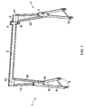
- the gantry shown in Figure 1 comprises two upright side frames 1 connected by a horizontal beam 2 supporting a beam trolley 3 that runs along the beam on wheels 4 and has a lifting eye 5.
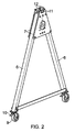
- the side frames 1 each comprise a pair of legs 6 joined at their top by a pair of connecting plates 7 which diverge downwards and are connected at their bottom by a tie bar 8.
- a wheel 9 is connected to the bottom of each leg 6 and is provided with a brake 10.
- the legs 6 are tubular with a rectangular section and their side faces abut the plates 7 either side.
- the plates 7 are of a generally triangular shape to match the profile of the diverging legs 6 and each have a pair of upwardly projecting lugs 11 at their upper end to form mounting points for a pair of guide wheels 12 located between respective pairs of lugs 11 either side of a central vertical gap between the two plates.
- This gap is designed to receive an upright adjustable support 13, the top of which is connected to one end of the horizontal beam 2.
- the support 13 is a tubular member with a substantially rectangular section and has channels 14 formed longitudinally in opposite sides.
- a roller link chain 15 is fitted in one of these channels for engagement by a drive gear 16 to determine the vertical position of the support 13.
- a second pair of wheels 12 is mounted between the plates 7 below the drive gear 16 to engage and support the sides of the support 13.
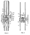
- the drive gear 16 is mounted on a drive spindle 17 between the two plates 7.
- the spindle 17 rotates in plain bearings in the plates 7 and a hand wheel 18 is mounted on the spindle 17 outboard of the outer plate 7 so as to be accessible for operation by a user to drive the drive gear 16.
- Grub screws 37 fasten the hand wheel 18 to the spindle 17.
- the hand wheel 18 drives the gear 16 via a drive train mounted between the plates 7 on the spindle 17 and two lay spindles 19 and 20.
- the drive train comprises an input gear 21 that is fixedly mounted on the spindle 17 and which meshes with a larger gear 22 of a double gear rotatably mounted on the lay spindle 19.
- a smaller gear 23 of the double gear meshes with a larger gear 24 of a double gear rotatably mounted on the second lay spindle 20, and a smaller gear 25 meshes with a third gear 26 rotatably mounted on the lay spindle 19 and substantially the same diameter as the gear 22 on the same spindle.
- the gear 26 meshes with a smaller gear 27 that is integral with the drive gear 16 as a double gear rotatably mounted on the spindle 17.
- a drive train comprises seven gears with ratios such as to generate a mechanical advantage for the hand wheel 18 in rotating the drive gear 16 so as to move the chain 15 and support 13 vertically.
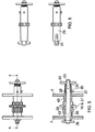
- the spindle 17 comprises a square section rod 28 with a cylindrical sleeve 29 as a close fit over it.
- a pin 30 extends laterally through the rod 28 and projects either end to engage a pair of longitudinal slots 31 in the sleeve 29 so as to key the rod and sleeve together for rotation but to allow the rod to move axially within the sleeve 29.
- a disc 32 is connected by a screw 33 to one end of the rod 28 extending from the sleeve 29, and compresses a helical spring 34 that is received within a counterbore 35 in the open end of the sleeve 29 around the rod 28.
- the spring 34 serves to urge the rod 28 outwardly of the sleeve 29 until the pin 30 engages the bases of the slots 31.
- the end of the rod 28 opposite the disc 32 also extends from the sleeve 29 and is fitted with a second pin 36 that extends laterally in alignment with the slots 31 (although this is optional as the pin 36 does not need to engage the slots 31).
- the spindle 17 is installed with the disc 32 and grease points 37 outboard of the one plate 7, and with the second pin 36 outboard of the other plate 7.
- the outer face of this other plate 7 is provided with a series of projections 38 spaced around the end of the spindle so as to form spaces therebetween in which the projecting ends of the pin 36 can engage in the manner of a dog gear.
- the spring 34 normally serves to urge the rod 28 axially so as to engage the dog gear, which serves to prevent rotation of the spindle 17.
- the dog gear 36, 38 therefore acts as a brake to prevent rotation of the spindle 17 until the disc 32 is depressed to disengage the dog gear 36, 38. Once the pin 36 is clear of the projections 38, the spindle is free to rotate.
- a strut member 40 is provided between the beam 2 and each side frame 1.
- the strut 40 comprises a tubular member similar to the support 13 and is connected at its lower end to the lower end of the support 13 where it projects below the plates 7. This connection 44 then limits the extent to which the support 13 and beam 2 can be raised vertically.
- the upper end of the strut 40 is connected to the beam 2 inboard of the support 13 via connection plates 41 either side. It will be appreciated that when the supports 13 and struts 40 are disconnected from the beam 2, the side frames 1 can be readily folded into a compact assembly for transport.
- the beam 2 preferably has a section as shown in Figure 7 with a substantially rectangular section which is used in the upright mode.
- the beam is a tubular extrusion and is formed with an internal lateral strengthening wall 45.
- the side walls of the beam in the central region are of reduced thickness to reduce weight.
- the walls of the beam top and bottom are of increased thickness to increase strength and to accommodate channels 46 at the bottom, opening outwards onto both sides.
- These channels 46 are provided to accommodate equipment such as electrical harnesses or means to drive the beam trolley.
- the channel might accommodate a chain with which a drive gear on a trolley engages in the manner of the drive gear 16 used for vertical adjustment in Figures 1 to 6 .
- the drive gear might engage a roller chain mounted in one slot 46, and a power pick-up for an electric motor drive of the drive gear might engage a power pick-up rail mounted in the opposite slot 46.
- a beam trolley may be connected to a chain in the manner of a continuous loop and engage gears at either end of the beam, one of which is driven.
- the adjust and lock mechanism shown in Figures 1 to 6 for vertical adjustment of the upright supports 13, is used to control the position of the beam trolley 3, the mechanism being incorporated into the trolley with the drive gear 16 in engagement with a roller link chain fitted in a channel 46.
Landscapes
- Engineering & Computer Science (AREA)
- Mechanical Engineering (AREA)
- Vehicle Cleaning, Maintenance, Repair, Refitting, And Outriggers (AREA)
- Transmission Devices (AREA)
- Carriers, Traveling Bodies, And Overhead Traveling Cranes (AREA)
Claims (12)
- Kranportal, umfassend:Seitenrahmen (1), die einen horizontalen Tragebalken (2) tragen, mit dem eine einstellbare Stütze (13) verbunden ist, undeinen Justier- und Sperrmechanismus,dadurch gekennzeichnet, dass der Justier- und Sperrmechanismus umfasst:ein Antriebszahnrad (16), das drehbar an einem der Seitenrahmen (1) befestigt und dazu geeignet ist, mit einer Antriebsschiene (15) an der einstellbaren Stütze (13) in Eingriff zu kommen, um durch Drehen des Antriebszahnrads (16) eine Einstellung zwischen dem Rahmen (1) der einstellbaren Stütze (13) zu ermöglichen,eine Antriebsachse (17), auf der das Antriebszahnrad (16) montiert ist und welche axial relativ zum Antriebszahnrad (16) in arretierenden Eingriff mit dem Rahmen (1) beweglich ist, um die Drehung zu verhindern,wobei die Antriebsachse (17) normalerweise in Sperreingriff mit dem Rahmen (1) federgespannt ist und wobei das Kranportal ferner einen manuell betriebenes Sperrlöseelement (32) umfasst, das so funktioniert, dass es die Antriebsachse (17) axial gegen die Federspannung (34) bewegt, um den arretierenden Eingriff zu lösen und zu ermöglichen, dass die Achse (17) gedreht wird, um das Antriebszahnrad (16) zu betätigen, während das Sperrlöseelement (32) betätigt gehalten wird.
- Kranportal nach Anspruch 1, bei dem der arretierende Eingriff durch einen radialen Vorsprung (36) auf der Achse (17) bereitgestellt wird, der mit einem Anschlag (38) in Eingriff bringbar und vom Anschlag (38) durch axiale Bewegung der Achse lösbar ist.
- Kranportal nach Anspruch 1 oder 2, bei dem das Antriebszahnrad (16) starr auf einer Hülse (38) montiert ist, in welcher sich die Achse (17) frei axial bewegen und drehen kann.
- Kranportal nach einem der vorherigen Ansprüche, bei dem das Sperrlöseelement (32) zur manuellen Betätigung zugänglich ist, um die Achse (17) axial gegen die Federspannung (34) zu bewegen.
- Kranportal nach Anspruch 4, bei dem das Sperrlöseelement (32) an einem Ende der Achse (17) angeordnet ist und der arretierende Eingriff (35, 38) mit dem Rahmen (1) am gegenüberliegenden Ende der Achse angeordnet ist.
- Kranportal nach Anspruch 4 oder 5, bei dem eine manuelle Justiersteuerung (18) vorgesehen ist, die zur manuellen Betätigung zugänglich ist, um die Achse (17) zu drehen, und direkt neben dem Sperrlöseelement (32) zur kombinierten Betätigung angeordnet ist.
- Kranportal nach einem der vorherigen Ansprüche, das ein Getriebe (21-27) enthält, um Drehung von der Achse (17) auf das Antriebszahnrad (16) zu übertragen.
- Kranportal nach einem der vorherigen Ansprüche, bei dem der Rahmen (3) so befestigt ist, dass er am Element (2) beweglich ist.
- Kranportal nach Anspruch 8, bei dem der Rahmen eine mobile Einheit (3) umfasst und das Element (2) eine Schiene (15, 47) umfasst, entlang derer die mobile Einheit (3) bewegt werden kann.
- Kranportal nach einem der Ansprüche 1 bis 7, bei dem der Rahmen (1) einen Teil einer Gerüststruktur umfasst, die ein vertikal einstellbares aufrechtes Element (13) trägt.
- Kranportal nach einem der vorherigen Ansprüche, bei dem die Antriebsschiene (15) eine Kette umfasst, die am Element (1, 2) zum Eingriff mit dem Antriebszahnrad (16) ortsbefestigt ist.
- Kranportal nach Anspruch 11, bei dem die Kette (15) in einem Kanal (14, 47) im Element (1, 2) montiert ist.
Applications Claiming Priority (2)
| Application Number | Priority Date | Filing Date | Title |
|---|---|---|---|
| GB0722596A GB2454733B (en) | 2007-11-16 | 2007-11-16 | Adjust and lock mechanism |
| PCT/EP2008/065675 WO2009063091A1 (en) | 2007-11-16 | 2008-11-17 | Adjust and lock mechanism |
Publications (2)
| Publication Number | Publication Date |
|---|---|
| EP2209732A1 EP2209732A1 (de) | 2010-07-28 |
| EP2209732B1 true EP2209732B1 (de) | 2016-07-27 |
Family
ID=38896487
Family Applications (1)
| Application Number | Title | Priority Date | Filing Date |
|---|---|---|---|
| EP08848606.3A Not-in-force EP2209732B1 (de) | 2007-11-16 | 2008-11-17 | Justierungs- und sperrmechanismus |
Country Status (4)
| Country | Link |
|---|---|
| US (1) | US8727146B2 (de) |
| EP (1) | EP2209732B1 (de) |
| GB (1) | GB2454733B (de) |
| WO (1) | WO2009063091A1 (de) |
Families Citing this family (6)
| Publication number | Priority date | Publication date | Assignee | Title |
|---|---|---|---|---|
| GB2514280B (en) | 2011-05-18 | 2015-04-01 | Reid Lifting Ltd | A trolley |
| US9630816B1 (en) * | 2013-03-11 | 2017-04-25 | Oz Lifting Products, LLC | Portable crane formed of composite members |
| CN106800249B (zh) * | 2016-12-20 | 2017-12-05 | 嵊州北航投星空众创科技有限公司 | 一种用于移动电力设备的起重机 |
| CN107256742B (zh) * | 2017-07-25 | 2023-05-16 | 上饶市达淋新材料有限公司 | 导体截面可变ffc的加工方法 |
| CN112279124B (zh) * | 2020-12-15 | 2021-05-21 | 蚌埠市江南建筑机械有限公司 | 一种起重机过载预警起重臂 |
| CN115676645B (zh) * | 2023-01-04 | 2023-03-21 | 中国电建集团山东电力建设第一工程有限公司 | 一种用于海上电力施工的大型工具吊装设备 |
Citations (1)
| Publication number | Priority date | Publication date | Assignee | Title |
|---|---|---|---|---|
| US4527680A (en) * | 1982-04-10 | 1985-07-09 | Yuji Sato | Locking device for movable storage rack |
Family Cites Families (13)
| Publication number | Priority date | Publication date | Assignee | Title |
|---|---|---|---|---|
| DE15366C (de) | H. MEINECKE in Breslau | Neuerung an Hebevorrichtungen | ||
| US1393218A (en) * | 1920-06-19 | 1921-10-11 | William J Herrbold | Portable hoist |
| US1931655A (en) * | 1930-08-01 | 1933-10-24 | Miner Inc W H | Clutch means |
| US2000078A (en) * | 1930-08-01 | 1935-05-07 | Miner Inc W H | Hand brake |
| US2493342A (en) | 1945-09-18 | 1950-01-03 | Cons Vultee Aircraft Corp | Offset landing gear strut with continuously circulating ball type bearing |
| BE463939A (de) | 1946-03-19 | 1946-04-30 | ||
| US2493242A (en) * | 1947-12-13 | 1950-01-03 | Patent Scaffolding Co Inc | Scaffold hoist holding means |
| US3263831A (en) * | 1964-10-19 | 1966-08-02 | Francis Geoffrey | Palletized storage device |
| NL6618476A (de) * | 1966-12-30 | 1968-07-01 | ||
| US4334480A (en) * | 1978-09-22 | 1982-06-15 | Wallace Bernard E | Gantries |
| NL8700771A (nl) * | 1987-04-01 | 1988-11-01 | Hendrikus Gerardus Janssen | Mobiele kraan. |
| FR2754552B1 (fr) * | 1996-10-11 | 2002-08-23 | Mothe Gerard Maurice | Portique motorise |
| WO2000076901A1 (en) * | 1999-06-15 | 2000-12-21 | East/West Industries, Inc. | Lifting system |
-
2007
- 2007-11-16 GB GB0722596A patent/GB2454733B/en not_active Expired - Fee Related
-
2008
- 2008-11-17 US US12/743,108 patent/US8727146B2/en not_active Expired - Fee Related
- 2008-11-17 WO PCT/EP2008/065675 patent/WO2009063091A1/en not_active Ceased
- 2008-11-17 EP EP08848606.3A patent/EP2209732B1/de not_active Not-in-force
Patent Citations (1)
| Publication number | Priority date | Publication date | Assignee | Title |
|---|---|---|---|---|
| US4527680A (en) * | 1982-04-10 | 1985-07-09 | Yuji Sato | Locking device for movable storage rack |
Also Published As
| Publication number | Publication date |
|---|---|
| US8727146B2 (en) | 2014-05-20 |
| US20100319476A1 (en) | 2010-12-23 |
| GB2454733A (en) | 2009-05-20 |
| GB0722596D0 (en) | 2007-12-27 |
| WO2009063091A1 (en) | 2009-05-22 |
| GB2454733B (en) | 2012-09-26 |
| EP2209732A1 (de) | 2010-07-28 |
Similar Documents
| Publication | Publication Date | Title |
|---|---|---|
| EP2209732B1 (de) | Justierungs- und sperrmechanismus | |
| US7954602B2 (en) | Lift apparatus with telescoping platform attachment and method | |
| US20170166426A1 (en) | Hoist device for a scaffold | |
| US7325654B2 (en) | List apparatuses and method | |
| US8596616B1 (en) | Winch for raising and lowering theatre scenery | |
| CN114890334A (zh) | 空调外机户外安装设备 | |
| CN115441341A (zh) | 一种手车检修操作装置 | |
| CN118206001B (zh) | 一种建筑钢结构装配用吊运装置 | |
| CN221138071U (zh) | 一种多层自动滚道梁装置及其长钢轨运输车组 | |
| US6315346B1 (en) | Load and lock tailgate | |
| DE3316034C2 (de) | Treppenlift, insbesondere zur Beförderung gehbehinderter Personen im Rollstuhl oder dergleichen | |
| EP2883831A1 (de) | Kleinteilegerät | |
| DE29903147U1 (de) | Einrichtung zur Raumgestaltung und Raumumwandlung | |
| DE3636440C1 (en) | Transport facility for transporting disabled persons in a wheelchair | |
| CN115195833A (zh) | 一种手车式开关设备转运车 | |
| CN208673905U (zh) | 用于变压器铁心线圈卷绕的可垂直自动升降操作平台 | |
| CN223054083U (zh) | 一种用于课堂教学的手动升降学生课桌及课椅 | |
| CN119612345B (zh) | 一种具有可分离副钩小车的起重机械及吊装方法 | |
| CN221662564U (zh) | 一种用于电力工程施工的设备升降装置 | |
| CN115764655B (zh) | 互感器安装转运手车 | |
| CN221585456U (zh) | 一种钢结构转运装置 | |
| CN221568326U (zh) | 一种室内装修用扶梯 | |
| RU2287476C2 (ru) | Лифт для инвалида в коляске, самоустанавливающийся в горизонтальной плоскости | |
| WO2010100532A1 (de) | Seilbahnlaufgestell mit zugseilen, seilbahnwagen und seilbahnanlage | |
| CN120681633A (zh) | 一种有限空间垂直运输及应急救援装置 |
Legal Events
| Date | Code | Title | Description |
|---|---|---|---|
| PUAI | Public reference made under article 153(3) epc to a published international application that has entered the european phase |
Free format text: ORIGINAL CODE: 0009012 |
|
| 17P | Request for examination filed |
Effective date: 20100513 |
|
| AK | Designated contracting states |
Kind code of ref document: A1 Designated state(s): AT BE BG CH CY CZ DE DK EE ES FI FR GB GR HR HU IE IS IT LI LT LU LV MC MT NL NO PL PT RO SE SI SK TR |
|
| AX | Request for extension of the european patent |
Extension state: AL BA MK RS |
|
| DAX | Request for extension of the european patent (deleted) | ||
| 17Q | First examination report despatched |
Effective date: 20120510 |
|
| GRAP | Despatch of communication of intention to grant a patent |
Free format text: ORIGINAL CODE: EPIDOSNIGR1 |
|
| INTG | Intention to grant announced |
Effective date: 20160216 |
|
| GRAS | Grant fee paid |
Free format text: ORIGINAL CODE: EPIDOSNIGR3 |
|
| RIN1 | Information on inventor provided before grant (corrected) |
Inventor name: RADMALL, PAUL |
|
| GRAA | (expected) grant |
Free format text: ORIGINAL CODE: 0009210 |
|
| RAP1 | Party data changed (applicant data changed or rights of an application transferred) |
Owner name: REID LIFTING LIMITED |
|
| AK | Designated contracting states |
Kind code of ref document: B1 Designated state(s): AT BE BG CH CY CZ DE DK EE ES FI FR GB GR HR HU IE IS IT LI LT LU LV MC MT NL NO PL PT RO SE SI SK TR |
|
| REG | Reference to a national code |
Ref country code: GB Ref legal event code: FG4D |
|
| REG | Reference to a national code |
Ref country code: CH Ref legal event code: EP |
|
| REG | Reference to a national code |
Ref country code: AT Ref legal event code: REF Ref document number: 815637 Country of ref document: AT Kind code of ref document: T Effective date: 20160815 |
|
| REG | Reference to a national code |
Ref country code: IE Ref legal event code: FG4D |
|
| REG | Reference to a national code |
Ref country code: DE Ref legal event code: R096 Ref document number: 602008045355 Country of ref document: DE |
|
| REG | Reference to a national code |
Ref country code: LT Ref legal event code: MG4D |
|
| REG | Reference to a national code |
Ref country code: NL Ref legal event code: MP Effective date: 20160727 |
|
| REG | Reference to a national code |
Ref country code: AT Ref legal event code: MK05 Ref document number: 815637 Country of ref document: AT Kind code of ref document: T Effective date: 20160727 |
|
| PG25 | Lapsed in a contracting state [announced via postgrant information from national office to epo] |
Ref country code: LT Free format text: LAPSE BECAUSE OF FAILURE TO SUBMIT A TRANSLATION OF THE DESCRIPTION OR TO PAY THE FEE WITHIN THE PRESCRIBED TIME-LIMIT Effective date: 20160727 Ref country code: IS Free format text: LAPSE BECAUSE OF FAILURE TO SUBMIT A TRANSLATION OF THE DESCRIPTION OR TO PAY THE FEE WITHIN THE PRESCRIBED TIME-LIMIT Effective date: 20161127 Ref country code: FI Free format text: LAPSE BECAUSE OF FAILURE TO SUBMIT A TRANSLATION OF THE DESCRIPTION OR TO PAY THE FEE WITHIN THE PRESCRIBED TIME-LIMIT Effective date: 20160727 Ref country code: IT Free format text: LAPSE BECAUSE OF FAILURE TO SUBMIT A TRANSLATION OF THE DESCRIPTION OR TO PAY THE FEE WITHIN THE PRESCRIBED TIME-LIMIT Effective date: 20160727 Ref country code: NL Free format text: LAPSE BECAUSE OF FAILURE TO SUBMIT A TRANSLATION OF THE DESCRIPTION OR TO PAY THE FEE WITHIN THE PRESCRIBED TIME-LIMIT Effective date: 20160727 Ref country code: HR Free format text: LAPSE BECAUSE OF FAILURE TO SUBMIT A TRANSLATION OF THE DESCRIPTION OR TO PAY THE FEE WITHIN THE PRESCRIBED TIME-LIMIT Effective date: 20160727 Ref country code: NO Free format text: LAPSE BECAUSE OF FAILURE TO SUBMIT A TRANSLATION OF THE DESCRIPTION OR TO PAY THE FEE WITHIN THE PRESCRIBED TIME-LIMIT Effective date: 20161027 |
|
| PG25 | Lapsed in a contracting state [announced via postgrant information from national office to epo] |
Ref country code: PL Free format text: LAPSE BECAUSE OF FAILURE TO SUBMIT A TRANSLATION OF THE DESCRIPTION OR TO PAY THE FEE WITHIN THE PRESCRIBED TIME-LIMIT Effective date: 20160727 Ref country code: LV Free format text: LAPSE BECAUSE OF FAILURE TO SUBMIT A TRANSLATION OF THE DESCRIPTION OR TO PAY THE FEE WITHIN THE PRESCRIBED TIME-LIMIT Effective date: 20160727 Ref country code: PT Free format text: LAPSE BECAUSE OF FAILURE TO SUBMIT A TRANSLATION OF THE DESCRIPTION OR TO PAY THE FEE WITHIN THE PRESCRIBED TIME-LIMIT Effective date: 20161128 Ref country code: AT Free format text: LAPSE BECAUSE OF FAILURE TO SUBMIT A TRANSLATION OF THE DESCRIPTION OR TO PAY THE FEE WITHIN THE PRESCRIBED TIME-LIMIT Effective date: 20160727 Ref country code: ES Free format text: LAPSE BECAUSE OF FAILURE TO SUBMIT A TRANSLATION OF THE DESCRIPTION OR TO PAY THE FEE WITHIN THE PRESCRIBED TIME-LIMIT Effective date: 20160727 Ref country code: SE Free format text: LAPSE BECAUSE OF FAILURE TO SUBMIT A TRANSLATION OF THE DESCRIPTION OR TO PAY THE FEE WITHIN THE PRESCRIBED TIME-LIMIT Effective date: 20160727 Ref country code: GR Free format text: LAPSE BECAUSE OF FAILURE TO SUBMIT A TRANSLATION OF THE DESCRIPTION OR TO PAY THE FEE WITHIN THE PRESCRIBED TIME-LIMIT Effective date: 20161028 Ref country code: BE Free format text: LAPSE BECAUSE OF NON-PAYMENT OF DUE FEES Effective date: 20160727 |
|
| REG | Reference to a national code |
Ref country code: FR Ref legal event code: PLFP Year of fee payment: 9 |
|
| PG25 | Lapsed in a contracting state [announced via postgrant information from national office to epo] |
Ref country code: EE Free format text: LAPSE BECAUSE OF FAILURE TO SUBMIT A TRANSLATION OF THE DESCRIPTION OR TO PAY THE FEE WITHIN THE PRESCRIBED TIME-LIMIT Effective date: 20160727 Ref country code: RO Free format text: LAPSE BECAUSE OF FAILURE TO SUBMIT A TRANSLATION OF THE DESCRIPTION OR TO PAY THE FEE WITHIN THE PRESCRIBED TIME-LIMIT Effective date: 20160727 |
|
| REG | Reference to a national code |
Ref country code: DE Ref legal event code: R097 Ref document number: 602008045355 Country of ref document: DE |
|
| PG25 | Lapsed in a contracting state [announced via postgrant information from national office to epo] |
Ref country code: SK Free format text: LAPSE BECAUSE OF FAILURE TO SUBMIT A TRANSLATION OF THE DESCRIPTION OR TO PAY THE FEE WITHIN THE PRESCRIBED TIME-LIMIT Effective date: 20160727 Ref country code: BG Free format text: LAPSE BECAUSE OF FAILURE TO SUBMIT A TRANSLATION OF THE DESCRIPTION OR TO PAY THE FEE WITHIN THE PRESCRIBED TIME-LIMIT Effective date: 20161027 Ref country code: CZ Free format text: LAPSE BECAUSE OF FAILURE TO SUBMIT A TRANSLATION OF THE DESCRIPTION OR TO PAY THE FEE WITHIN THE PRESCRIBED TIME-LIMIT Effective date: 20160727 Ref country code: DK Free format text: LAPSE BECAUSE OF FAILURE TO SUBMIT A TRANSLATION OF THE DESCRIPTION OR TO PAY THE FEE WITHIN THE PRESCRIBED TIME-LIMIT Effective date: 20160727 |
|
| PLBE | No opposition filed within time limit |
Free format text: ORIGINAL CODE: 0009261 |
|
| STAA | Information on the status of an ep patent application or granted ep patent |
Free format text: STATUS: NO OPPOSITION FILED WITHIN TIME LIMIT |
|
| REG | Reference to a national code |
Ref country code: CH Ref legal event code: PL |
|
| 26N | No opposition filed |
Effective date: 20170502 |
|
| PG25 | Lapsed in a contracting state [announced via postgrant information from national office to epo] |
Ref country code: LI Free format text: LAPSE BECAUSE OF NON-PAYMENT OF DUE FEES Effective date: 20161130 Ref country code: CH Free format text: LAPSE BECAUSE OF NON-PAYMENT OF DUE FEES Effective date: 20161130 |
|
| REG | Reference to a national code |
Ref country code: IE Ref legal event code: MM4A |
|
| PG25 | Lapsed in a contracting state [announced via postgrant information from national office to epo] |
Ref country code: SI Free format text: LAPSE BECAUSE OF FAILURE TO SUBMIT A TRANSLATION OF THE DESCRIPTION OR TO PAY THE FEE WITHIN THE PRESCRIBED TIME-LIMIT Effective date: 20160727 |
|
| PG25 | Lapsed in a contracting state [announced via postgrant information from national office to epo] |
Ref country code: LU Free format text: LAPSE BECAUSE OF NON-PAYMENT OF DUE FEES Effective date: 20161130 |
|
| REG | Reference to a national code |
Ref country code: FR Ref legal event code: PLFP Year of fee payment: 10 |
|
| PG25 | Lapsed in a contracting state [announced via postgrant information from national office to epo] |
Ref country code: IE Free format text: LAPSE BECAUSE OF NON-PAYMENT OF DUE FEES Effective date: 20161117 |
|
| PG25 | Lapsed in a contracting state [announced via postgrant information from national office to epo] |
Ref country code: HU Free format text: LAPSE BECAUSE OF FAILURE TO SUBMIT A TRANSLATION OF THE DESCRIPTION OR TO PAY THE FEE WITHIN THE PRESCRIBED TIME-LIMIT; INVALID AB INITIO Effective date: 20081117 Ref country code: CY Free format text: LAPSE BECAUSE OF FAILURE TO SUBMIT A TRANSLATION OF THE DESCRIPTION OR TO PAY THE FEE WITHIN THE PRESCRIBED TIME-LIMIT Effective date: 20160727 |
|
| PG25 | Lapsed in a contracting state [announced via postgrant information from national office to epo] |
Ref country code: MC Free format text: LAPSE BECAUSE OF FAILURE TO SUBMIT A TRANSLATION OF THE DESCRIPTION OR TO PAY THE FEE WITHIN THE PRESCRIBED TIME-LIMIT Effective date: 20160727 Ref country code: TR Free format text: LAPSE BECAUSE OF FAILURE TO SUBMIT A TRANSLATION OF THE DESCRIPTION OR TO PAY THE FEE WITHIN THE PRESCRIBED TIME-LIMIT Effective date: 20160727 |
|
| PG25 | Lapsed in a contracting state [announced via postgrant information from national office to epo] |
Ref country code: MT Free format text: LAPSE BECAUSE OF NON-PAYMENT OF DUE FEES Effective date: 20161117 |
|
| PGFP | Annual fee paid to national office [announced via postgrant information from national office to epo] |
Ref country code: DE Payment date: 20201127 Year of fee payment: 13 Ref country code: FR Payment date: 20201127 Year of fee payment: 13 Ref country code: GB Payment date: 20201126 Year of fee payment: 13 |
|
| REG | Reference to a national code |
Ref country code: DE Ref legal event code: R119 Ref document number: 602008045355 Country of ref document: DE |
|
| GBPC | Gb: european patent ceased through non-payment of renewal fee |
Effective date: 20211117 |
|
| PG25 | Lapsed in a contracting state [announced via postgrant information from national office to epo] |
Ref country code: GB Free format text: LAPSE BECAUSE OF NON-PAYMENT OF DUE FEES Effective date: 20211117 Ref country code: DE Free format text: LAPSE BECAUSE OF NON-PAYMENT OF DUE FEES Effective date: 20220601 |
|
| PG25 | Lapsed in a contracting state [announced via postgrant information from national office to epo] |
Ref country code: FR Free format text: LAPSE BECAUSE OF NON-PAYMENT OF DUE FEES Effective date: 20211130 |