EP2209947B1 - Procédé d'introduction d'un élément de fondation allongé dans le sol - Google Patents
Procédé d'introduction d'un élément de fondation allongé dans le sol Download PDFInfo
- Publication number
- EP2209947B1 EP2209947B1 EP08766727.5A EP08766727A EP2209947B1 EP 2209947 B1 EP2209947 B1 EP 2209947B1 EP 08766727 A EP08766727 A EP 08766727A EP 2209947 B1 EP2209947 B1 EP 2209947B1
- Authority
- EP
- European Patent Office
- Prior art keywords
- foundation element
- ground
- driving shaft
- drilling
- drilling head
- Prior art date
- Legal status (The legal status is an assumption and is not a legal conclusion. Google has not performed a legal analysis and makes no representation as to the accuracy of the status listed.)
- Active
Links
Images


Classifications
-
- E—FIXED CONSTRUCTIONS
- E02—HYDRAULIC ENGINEERING; FOUNDATIONS; SOIL SHIFTING
- E02D—FOUNDATIONS; EXCAVATIONS; EMBANKMENTS; UNDERGROUND OR UNDERWATER STRUCTURES
- E02D7/00—Methods or apparatus for placing sheet pile bulkheads, piles, mouldpipes, or other moulds
- E02D7/28—Placing of hollow pipes or mould pipes by means arranged inside the piles or pipes
Definitions
- the present invention relates to a method for introducing an elongated foundation element at least partially into the ground according to the preamble of claim 1.
- a prefabricated foundation element is introduced into the tube after introducing the tube into the ground, whereupon the cavities between the inner tube wall and the foundation element are filled up with concrete, while the tube is lifted up again before the concrete sets.
- a hole is drilled after which the foundation element is placed into the drilled hole.
- JP2002081059 discloses a method in which an elongated foundation element is introduced into the soil using a drilling head provided with a spiral blade. Rotating the drilling head drives the drilling head into the ground, and it also pushes soil sideways; allowing the foundation element to be introduced. The drilling head remains in the ground after drilling. The method allows for a reduced risk of damage to the elongated driving pile due to torsional forces.
- the object of the present invention is to provide a method for introducing an elongated prefab foundation element at least partially into the ground, which causes little nuisance, little damage to the surroundings, and is cost effective.
- the invention provides a method for introducing an elongated prefab foundation element at least partially into the ground, comprising the steps as mentioned in claim 1.
- the invention provides for introduction of a prefabricated foundation element into the ground.
- An important advantage that is achieved this way is that the load bearing capacity of such an element is better known beforehand, which is important for the construction of a building that is to be build on the foundation.
- the foundation element is not exposed to impact loading which limits the risk of cracking of the foundation element.
- the reinforcement can also be closer to the surface of the foundation element than with foundation elements that are introduced into the ground by pile driving.
- the reinforcement can be prestressed reinforcement for those applications where the foundation element (also) has to be able to withstand pulling forces.
- the foundation element can be provided with a conduit for storing heat and/or cold in the ground or withdrawing heat and/or cold from the ground.
- such a conduit may also be introduced into the channel after introducing the foundation element into the ground.
- the invention is extremely suitable for introducing foundation elements that are not round, which contributes to the economical aspect even more.
- the total of the rotating surface area that is in contact with the ground is significantly smaller or even zero (apart from, of course, the drilling head), in comparison with the technique of rotating a hollow tube into the ground, since the foundation element will not co-rotate simultaneously, or only slightly, thus reducing the friction and thus reducing the energy required for the introduction.
- the foundation element may have a circular cross section, but according to an important advantage of the invention the cross section may instead be unround, such as elliptical, a regular or irregular polygon (e.g. pentagonal, hexagonal, heptagonal, octagonal, nonagonal, decagonal, and from the viewpoint of costs preferably quadrangular or rectangular) etc., yet achieving a proper adhesive force of the outer longitudinal sides and/or longitudinal ribs of the foundation element to the ground.
- a channel is mentioned, a through-space in the longitudinal direction of the foundation element is meant.
- the foundation element is a hollow foundation element.
- the phrase "hollow foundation element” means that in cross section the foundation element exhibits a hole, which hole is the channel into which the driving shaft is introduced.
- the space opens up at one side of the foundation element.
- the foundation element has for instance a U-shaped cross section.
- the central axis of the foundation element will in practice be within the space. The position of the central axis can be determined by wrapping an (imaginary) wire around the foundation element in a plane perpendicular to the longitudinal direction of the foundation element.
- the central axis is the line that runs in the longitudinal direction of the foundation element through the place-average centre of the circumference that is determined by the wire.
- the largest diameter of the foundation element is defined as twice the distance between the central axis and a point situated on the wire that is located furthest away of the central axis.
- the smallest diameter of the foundation element is defined as twice the distance between the central axis and a point situated on the imaginary wire that is located nearest to the central axis.
- the method is carried out such that the ground is cut through by the drilling head less than 1 cm beyond the largest diameter of the foundation element, more preferably, the ground is not cut through beyond the largest diameter.
- the diameter of the drilling head may also be somewhat smaller in which case the foundation elements may allow for an adhesive (friction) load, while intermediate areas have no adhesion until the ground around the foundation element has settled. Because of the selected shape and the rotating movement, the drilling head pushes away the earth sidewards, facilitated by the downward force exerted by the drilling head via the driving shaft. A (generally significantly smaller) downward force will be exerted on the foundation element also in order to ensure that the drilling head and the foundation element are not separated from one another to such an extent that the foundation element is no longer moved downward together with the drilling head.
- the downward pull and/or push force exerted on the drilling engine by a device is at least 1 ton (i.e. 1 ton more than the tare weight of the totality of the drilling engine, foundation element and driving shaft), preferably at least 2 tons.
- This force is selected depending on the chosen circumstances (ground conditions, pile diameter, shape of the drilling head etc.), but can be readily determined by the ordinary expert: When the foundation element does not enter the ground or does not enter the ground quickly enough, the downward force has to be increased.
- the foundation element that has to be introduced into the ground will have over its length essentially the same dimensions (cross section).
- the ground that is pushed away by the drilling head will be displaced at least partially and in practice virtually entirely sidewards.
- which driving shaft is driven near the top end of the foundation element is mentioned, this is intended to mean: At a greater distance from the lower end of the foundation element than from the top end.
- the driving shaft will be driven by the drilling engine at the upper end of the foundation element.
- By exerting the downward force it is also possible to introduce a prefab foundation element by drilling at an angle. This angle is for instance at least 5°, but can also be more than 10°.
- the downwardly directed force exerted on the drilling head is greater than the force that may be exerted on the foundation element. With the method according to the invention the drilling head remains in the ground.
- DE19746731A1 discloses a system in which a sheet pile element is introduced into the ground wherein soil is loosened up by a drilling head and placed into a container which is regularly moved to the earth's surface to be emptied there. In order to achieve some load bearing capacity, grout has to be introduced at the bottom of the sheet pile element.
- JP2003147770 discloses a method for introducing a foundation element into the ground wherein a drilling head is screwed into the ground.
- the load bearing strength of the foundation element is determined by the strength of the attachment of the spiral-shaped flange of the drilling head to the body of the drilling head, generally a weld.
- the flange may be an integrally cast portion, in which case the drilling head is very expensive, especially since the drilling head remains in the ground.
- essentially only circular foundation elements can be (accurately) placed.
- the drilling head will substantially be a closed head (as a result of which at the most a negligible amount of soil will end up in the channel).
- the drilling head can be loaded very effectively.
- the ground below the head is compressed, resulting in less settlement.
- DE 20 2004 020804 discloses a method for introducing a foundation element into the ground, said foundation element having a central channel for an auger which is used to transport soil to the surface. It discloses the use of a chisel head to interrupt the introduction of the foundation element to break up stones and the like.
- GB1125853 discloses a method for introducing an elongated prefab foundation element into the ground.
- the elongated prefab foundation comprises a channel extending along its length where a driving shaft is connected to a drilling head provided at the bottom of the prefab foundation element, said driving shaft with an auger being driven by a drilling engine.
- the engine is moved up and down by a platform to control the height of the drilling head and to clamp a bucket where the soil is to be stored.
- the driving shaft and the drilling head engage detachably and the driving shaft is removed from the channel of the foundation element after the foundation element has at least been partially introduced into the ground.
- the driving shaft can be used for the introduction into a channel of a subsequent foundation element.
- the driving shaft is retained by the drilling engine. In such a case, with this favorable embodiment, this retention can be used to pull the driving shaft up from the channel.
- the drilling head has a largest diameter between the smallest diameter and the largest diameter of the foundation element.
- a foundation element that is not round can be introduced into the ground quickly, while the ground is further minimally disturbed and can accommodate itself to the foundation element around the foundation element.
- the diameter of an elongated foundation element is, as customary in the art, calculated transverse to the longitudinal direction of the elongated foundation element, and is defined hereabove exactly.
- the base of the foundation element is provided with an organ against which the drilling head can rotate with reduced friction, and wherein the organ is provided with an opening for letting through the driving shaft.
- the organ can be a coating that is applied either prior to, during or after the manufacture of the foundation element, or a separate organ that is placed, clenched to the lower end of the foundation element or fastened therewith for instance by gluing.
- the opening allows the driving shaft to reach the drilling head in order to be able to drive it.
- the foundation element is a foundation element that has a space in the longitudinal direction thereof such that it allows for the driving shaft to be introduced into the channel via a longitudinal side of the foundation element.
- This embodiment facilitates the introduction of the driving shaft into the channel, which saves time and costs. Consequently, the device for introducing the elongated foundation element into the ground can be significantly less high, which is a major advantage.
- the phrase "introducing the driving shaft into the channel via a longitudinal side of the foundation element" also includes fitting the driving shaft around the foundation element. For that matter, after introducing the driving shaft into the channel, the longitudinal side may be closed completely or partially thus forming a hollow foundation element as described above. In DE19746731A1 the space is used for passing through a protruding portion of the drilling head, and not for introducing the driving shaft via the longitudinal side.
- the application also discusses a device for the introduction of a foundation element into the ground, which device is not part of the claimed invention, and which device includes a drilling engine for driving a driving shaft that is substantially directed vertically, the driving shaft being adjustable in height with respect to the drilling engine, and wherein the device is provided with an organ for exerting a downwardly directed force on the drilling engine.
- Such a device is very flexible and, if so desired, can be used with hollow foundation elements or with foundation elements wherein the driving shaft is introduced into the channel via a longitudinal side of the foundation element.
- substantially vertically means at an angle between 45° and 90° with the horizontal.
- the organ for exerting a downwardly directed force is for instance a winch.
- the downwardly directed force can also be exerted hydraulically and/or using rack-and-pinion driving and/or a chain- and gear driving.
- Such a device can introduce a foundation element into the ground more quickly, and thus more economically.
- Such a device also allows the introduction of foundation elements into types of soil other than soft soil.
- the drilling engine is arranged to engage the driving shaft, and further the drilling engine is provided with a centering organ to centre the foundation element in order to prevent the driving shaft from touching the wall of the channel.
- the centering organ plays an important role in sparing the wall of the channel since it limits swerves of the upper end to a large extent.
- the centering organ which for instance has the shape of a coupling sleeve, also provides a downward pressure, or part thereof, on the foundation element when this stays behind relative to the drilling head because of sticking/adhesion when introducing it into the ground.
- the centering organ is advantageously suspended rotatably around an axis - that coincides with the rotating axis of the drilling engine - but in such a way that translation of the centering organ in a plane transverse to that axis is avoided to a large extent. This makes it possible to readily include the upper end of a foundation element that is not round in the centering organ.
- a drilling engine when a drilling engine is mentioned this also includes a drilling engine that is contained in a housing (case), where the housing includes the centering organ, the downward force is exerted on the housing and thus on the drilling engine etc. and that the term drilling engine hence also includes a housing therefore, as long as the housing includes a drilling engine, as a result of which such variants fall within the scope of the accompanying claims. If the driving shaft can be passed through the drilling engine, it can also be passed through the housing.
- Fig. 1 shows a device 1 suitable for use in the method according to the invention, which in the embodiment shown here is designed as a vehicle having caterpillar tracks 2.
- the vehicle includes a leader 3.
- a leader 3 is that part of the device that carries and guides the heavy vertically movable parts of the device.
- the leader 3 is provided with a drilling engine 4.
- This drilling engine 4 can be moved along the leader 3 in a manner known per se.
- the drilling engine 4 can drive a shaft 5.
- the drilling engine 4 is arranged such that the driving shaft 5 can be passed through the drilling engine 4 and can be held at a desired position on the driving shaft 5.
- the device 1 is a device that is substantially known, now first some known features of the device 1 as shown in figure 1 will be discussed.
- the leader 3 is connected with the vehicle such that it can be tilted via connecting element 25 capable of acting as a cardan joint.
- a hydraulic cylinder 26 is present for positioning the leader 3 at the desired height.
- the hydraulic cylinder 27 is present for positioning the leader 3 at the desired angle.
- cable 23 is connected to winch 29 in a manner known per se via pulleys 21 and 42.
- the device 1 For exerting a downward force on the drilling engine 4 the device 1 is provided with a winch 28, which force is transferred to the drilling engine 4 via cable 22 and a pulley 42.
- a winch 28 For the sake of the figure's clarity, the cable path within the leader 3 is not shown.
- the driving shaft 5 is preferably hollow.
- the diameter of the driving shaft 5 can vary depending on the diameter of a foundation element 100 to be introduced into the ground, and is for instance 10 - 20 cm. Its length will similarly also depend on the length of the foundation element as well as on the way in which the drilling engine 4 engages the driving shaft 5.
- An elongated foundation element 100 to be introduced into the ground using the method according to the invention has a channel 6 extending in the longitudinal direction of the foundation element, in general from one end of the foundation element 100 to the other.
- the driving shaft 5 is introduced into the channel 6.
- the way in which this can be done depends on the type of foundation element 100 that is used.
- the driving shaft 5 will be introduced into the channel 6 at one end of the foundation element 100. In practice, this will take place when the foundation element 100 is preferably at least partially erected, and preferably when it is in a substantially vertical position. Another option will be discussed later.
- a drilling head 7 also called drilling tip, is connected which is designed for mainly sideward displacement.
- a drilling head 7 is known per se, and is for instance available from Rademakers Gieterij BV, Klazienaveen, The Netherlands.
- the driving shaft 5 engages a cavity in the drilling head 7.
- the drilling head 7 is for instance manufactured out of cast iron.
- the diameter of the drilling head 7 will be selected depending on the type of soil, diameter and cross section (shape) of the foundation element 100 and the like. In case there is a risk of negative adhesion, this may be prevented by selecting a drilling head 7 having a large diameter that can be larger than the largest diameter of the foundation element 100. When using a downward force exerted upon the foundation element 100 the diameter of the drilling head 7 may be smaller than when no such force is exerted.
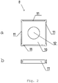
- an organ 8 may be provided, having at least 1 of the following functions: lowering the friction between the lower end of the foundation element 100 and the drilling head 7, avoiding that the driving shaft 5 touches the wall 9 of the channel and to make sure that the driving shaft 5 stays well centred in the channel 6.
- the organ 8 has for instance the shape of a plate 10 ( fig. 2 ) which at opposite ends is provided with upright edges 11 which are clamped around the lower end of the foundation element 100.
- the plate 10 further has a space or aperture 12 for letting through the driving shaft 5.
- the organ 8 is for instance manufactured out of cast iron.
- the drilling engine 4 will drive the driving shaft 5, causing the drilling head 7 to rotate.
- the drilling head 7 pushes away ground, mainly sidewards, as a result of which a hole is formed in the ground and at the same time foundation element 100 is introduced into the ground.
- the foundation element 100 does not rotate.
- exerting a large downward force will be necessary in order to be able to introduce a foundation element 100 into the ground when that ground is firm.
- also in the case of soft ground exerting a large downward force will be (economically) advantageous, as this saves time.
- the downward force is provided by exerting a downward force on the drilling engine 4, for instance by means of cable 22, pulley 42 and winch 28.
- a downward force can be exerted on the foundation element 100 also.
- the drilling engine 4 is at its bottom provided with a centering organ 30, here in the shape of a square coupling sleeve which is placed over the upper end of the foundation element 100, and incorporated therein.
- a centering organ can also use the channel to centre the foundation element 100.
- a guiding organ 41 is provided for guiding the foundation element 100.
- the guiding organ 41 is in the shape of two arms, which either clasp with low friction or loosely surround the foundation element 100.
- Fig. 3 shows the foundation element 100 partially introduced into the ground.
- the pulleys 20 and 42' (situated behind pulley 42) and cable 22 that are preferably used here also are, for that matter, not shown.
- a foundation element 100 can also be introduced into the ground at another angle than vertical.
- the leader 3 will be positioned at the same angle.
- the leader 3 When the device 1 is used for introducing a foundation element 100 into the ground, wherein the lumen of the channel 6 is in contact with the surroundings only at both ends of the foundation element, the leader 3 will be provided with an extension arm 16 that can be moved parallel to the leader 3, for instance in the form of a telescopic tube, which may be hydraulic or pneumatic, but preferably has a winch (not shown).
- the driving shaft 5 will be connected near the upper end thereof, in such a way that the driving shaft 5 is still able to rotate around its axis, or be arranged to release the driving shaft 5 when the drilling engine 4 has to drive the driving shaft 5 ( fig. 3 ).
- a foundation element 100 that is arranged to introduce the driving shaft 5 into the channel 6 via a longitudinal side of the foundation element.
- Fig. 4 shows four sectional views of foundation elements 100-103, wherein the foundation elements 102 and 103 at a longitudinal side have a side opening 104. In practice, this will extend along the entire length of the foundation elements 102, 103. However, it is, for instance, conceivable that an end of the foundation element 102, 103 has a cross section for foundation elements 100 or 101 as shown in fig. 4 , as long as the driving shaft (drilling rod) can be introduced into the channel 6 via the longitudinal side.
- the foundation elements 102, 103 can be said to have a U-shaped cross section.
- the central axis of the driving shaft 5 will generally coincide with the central axis of the channel 6, and the channel 6 will be dimensioned such that the outer periphery of the driving shaft 5 fits within the channel 6.
- the channel 6 will generally have an at least partially circular cross section, but this is not necessary.
- a hollow foundation element could for instance have a channel with a square cross section (not shown).
- the channel may, for example, be used for introducing a conduit for the thermal usage of the ground, reinforcement can be provided into the channel and embedded in grout, the driving shaft can be hollow and the cavity can be used to introduce a setting mass (such as grout) into the cavity during the pulling upwards of the driving shaft etc. It is also possible to introduce a foundation element in more than 1 part, wherein these parts, if so desired, are for example connected via a mortise and tenon joint.
Landscapes
- Engineering & Computer Science (AREA)
- Life Sciences & Earth Sciences (AREA)
- General Life Sciences & Earth Sciences (AREA)
- Mining & Mineral Resources (AREA)
- Paleontology (AREA)
- Civil Engineering (AREA)
- General Engineering & Computer Science (AREA)
- Structural Engineering (AREA)
- Earth Drilling (AREA)
Claims (6)
- Procédé d'introduction au moins partielle dans le sol d'un élément de fondation (100) préfabriqué allongé, l'élément de fondation (100) préfabriqué allongé comportant un canal (6) s'étendant suivant la longueur de l'élément de fondation (100),
dans lequel une tête de forage (7) disposée au fond de l'élément de fondation (100) creux est entraînée par un arbre de commande dans le canal (6) de l'élément de fondation (100), l'arbre de commande étant entraîné par un moteur de forage (4) près de l'extrémité supérieure de l'élément de fondation (100),
dans lequel la tête de forage est une tête de forage sensiblement fermée, le sol étant poussé sur le côté pratiquement entièrement et l'élément de fondation (100) étant introduit au moins partiellement dans le sol par l'entraînement de la tête de forage (7), à la suite de quoi la tête de forage (7) est laissée dans le sol,
caractérisé en ce qu'une force de traction et/ou de poussée dirigée vers le bas est exercée sur le moteur de forage (4) et par l'intermédiaire de l'arbre de commande (5) à la tête de forage (7) par un dispositif, dans lequel la force de traction et/ou de poussée dirigée vers le bas a pour résultat d'introduire l'élément de fondation (100) dans le sol. - Procédé selon la revendication 1, dans lequel le procédé comprend l'étape consistant à exercer sur le moteur de forage (4) une force dirigée vers le bas d'au moins 2 tonnes.
- Procédé selon l'une quelconque des revendications précédentes, dans lequel l'élément de fondation (100) est un élément de fondation (100) comportant une ouverture latérale dans sa direction longitudinale de telle sorte qu'il permet d'introduire l'arbre de commande dans le canal (6) par un côté longitudinal de l'élément de fondation (100).
- Procédé selon l'une quelconque des revendications précédentes, dans lequel l'arbre de commande et la tête de forage (7) sont en prise amovible, et l'arbre de commande est retiré du canal (6) de l'élément de fondation (100) après que l'élément de fondation (100) ait été au moins partiellement introduit dans le sol.
- Procédé selon l'une quelconque des revendications précédentes, dans lequel le plus grand diamètre de la tête de forage (7) est compris entre le plus petit diamètre et le plus grand diamètre de l'élément de fondation (100).
- Procédé selon l'une quelconque des revendications précédentes, dans lequel la base de l'élément de fondation (100) est pourvue d'un organe contre lequel la tête de forage (7) peut tourner avec un frottement réduit, dans lequel l'organe est pourvu d'une ouverture pour laisser l'arbre de commande passer à travers.
Applications Claiming Priority (2)
| Application Number | Priority Date | Filing Date | Title |
|---|---|---|---|
| NL1034016A NL1034016C2 (nl) | 2007-06-22 | 2007-06-22 | Werkwijze voor het in de bodem brengen van een langwerpig funderingselement, een inrichting daarvoor, alsmede een funderingselement. |
| PCT/NL2008/000154 WO2009002151A1 (fr) | 2007-06-22 | 2008-06-23 | Procédé d'introduction d'un élément de fondation allongé dans le sol et appareil à cet effet |
Publications (2)
| Publication Number | Publication Date |
|---|---|
| EP2209947A1 EP2209947A1 (fr) | 2010-07-28 |
| EP2209947B1 true EP2209947B1 (fr) | 2018-11-14 |
Family
ID=39745656
Family Applications (1)
| Application Number | Title | Priority Date | Filing Date |
|---|---|---|---|
| EP08766727.5A Active EP2209947B1 (fr) | 2007-06-22 | 2008-06-23 | Procédé d'introduction d'un élément de fondation allongé dans le sol |
Country Status (3)
| Country | Link |
|---|---|
| EP (1) | EP2209947B1 (fr) |
| NL (1) | NL1034016C2 (fr) |
| WO (1) | WO2009002151A1 (fr) |
Citations (4)
| Publication number | Priority date | Publication date | Assignee | Title |
|---|---|---|---|---|
| GB2060742A (en) * | 1979-10-12 | 1981-05-07 | Sanwa Kizai Co Ltd | Driving sheet piles |
| US4637758A (en) * | 1982-03-11 | 1987-01-20 | Kabushiki Kaisha Komatsu Seisakusho | Method of driving hollow piles into the ground |
| JP2002081059A (ja) * | 2000-06-20 | 2002-03-22 | Daido Concrete Co Ltd | 杭の埋設工法及びその装置 |
| DE202004020804U1 (de) * | 2004-12-10 | 2006-03-16 | Krinner Innovation Gmbh | Fundamenteinrichtung für stabförmige Bauteile mit mehrfach verwendbarem Werkzeug sowie Vorrichtung zum Einbringen einer derartigen Fundamenteinrichtung |
Family Cites Families (5)
| Publication number | Priority date | Publication date | Assignee | Title |
|---|---|---|---|---|
| GB1125853A (en) | 1967-01-16 | 1968-09-05 | Marutai Doboku Company Ltd | A pile driving apparatus including earth boring equipment |
| DE19746731A1 (de) * | 1997-10-13 | 1999-05-06 | Huang Chia Hsiung | C-Profil-Pfahl und Verfahren zum Einbringen von C-Profil-Pfählen |
| JP2002021062A (ja) * | 2000-07-06 | 2002-01-23 | Konoike Constr Ltd | ソイルセメント合成杭造成装置の掘削攪拌翼保持装置 |
| JP4523716B2 (ja) * | 2000-12-05 | 2010-08-11 | 株式会社トーヨーアサノ | 基礎杭の施工方法 |
| JP3989224B2 (ja) * | 2001-11-09 | 2007-10-10 | ジャパンパイル株式会社 | 杭の埋設装置 |
-
2007
- 2007-06-22 NL NL1034016A patent/NL1034016C2/nl not_active IP Right Cessation
-
2008
- 2008-06-23 WO PCT/NL2008/000154 patent/WO2009002151A1/fr not_active Ceased
- 2008-06-23 EP EP08766727.5A patent/EP2209947B1/fr active Active
Patent Citations (4)
| Publication number | Priority date | Publication date | Assignee | Title |
|---|---|---|---|---|
| GB2060742A (en) * | 1979-10-12 | 1981-05-07 | Sanwa Kizai Co Ltd | Driving sheet piles |
| US4637758A (en) * | 1982-03-11 | 1987-01-20 | Kabushiki Kaisha Komatsu Seisakusho | Method of driving hollow piles into the ground |
| JP2002081059A (ja) * | 2000-06-20 | 2002-03-22 | Daido Concrete Co Ltd | 杭の埋設工法及びその装置 |
| DE202004020804U1 (de) * | 2004-12-10 | 2006-03-16 | Krinner Innovation Gmbh | Fundamenteinrichtung für stabförmige Bauteile mit mehrfach verwendbarem Werkzeug sowie Vorrichtung zum Einbringen einer derartigen Fundamenteinrichtung |
Also Published As
| Publication number | Publication date |
|---|---|
| EP2209947A1 (fr) | 2010-07-28 |
| NL1034016C2 (nl) | 2008-12-23 |
| WO2009002151A1 (fr) | 2008-12-31 |
Similar Documents
| Publication | Publication Date | Title |
|---|---|---|
| US6540443B2 (en) | Apparatus for and a method of boring the ground | |
| ES2397273T3 (es) | Método y aparato para construir un puente | |
| US7070362B2 (en) | Reinforcement unit for a reinforcing a footing element when laying pile foundations with a pile, and method for placing a foundation pile and reinforcement of a footing element | |
| WO2009049470A1 (fr) | Machine à percussion et injection pour forage | |
| EP3181802B1 (fr) | Dispositif et procédé pour le mouvement et l'assemblage mutuel des segments d'une batterie d'excavation | |
| RU2076173C1 (ru) | Способ изготовления винтонабивной сваи и устройство для его осуществления | |
| US20090285637A1 (en) | Pile mandrel with extendable reaming members | |
| EP2209947B1 (fr) | Procédé d'introduction d'un élément de fondation allongé dans le sol | |
| JP5624401B2 (ja) | 地中障害物の吊上げ装置 | |
| CN109371961B (zh) | 一种地铁车站用钢管柱及其施工工艺 | |
| CN117845887A (zh) | 一种钢管桩地基基础加固机构 | |
| CN206385530U (zh) | 一种液压锤击式四翼预制桩 | |
| JP4187908B2 (ja) | 基礎杭回転圧入施工機 | |
| CN115928727A (zh) | 一种基坑倾斜桩施工方法 | |
| EP3351688B1 (fr) | Appareil et procédé permettant de stabiliser une fondation d'un bâtiment | |
| JP3683936B2 (ja) | 鋼管杭打撃工法およびその装置 | |
| GB2108185A (en) | Method of boring pile boles | |
| CN218667562U (zh) | 一种支护桩桩间土防护结构 | |
| CN215471979U (zh) | 一种管桩生产下料辅助装置 | |
| JP4388861B2 (ja) | 杭施工方法 | |
| JP2002146787A (ja) | 杭打ち装置 | |
| GB2363133A (en) | Forming foundation, e.g. for a post | |
| CN217651789U (zh) | 一种滑销式旧桩拔除装置 | |
| KR100479514B1 (ko) | 굴착 장치 및 방법 | |
| CN110185034B (zh) | 一种适用于沙漠地质条件的打桩设备及施工方法 |
Legal Events
| Date | Code | Title | Description |
|---|---|---|---|
| PUAI | Public reference made under article 153(3) epc to a published international application that has entered the european phase |
Free format text: ORIGINAL CODE: 0009012 |
|
| 17P | Request for examination filed |
Effective date: 20100119 |
|
| AK | Designated contracting states |
Kind code of ref document: A1 Designated state(s): AT BE BG CH CY CZ DE DK EE ES FI FR GB GR HR HU IE IS IT LI LT LU LV MC MT NL NO PL PT RO SE SI SK TR |
|
| AX | Request for extension of the european patent |
Extension state: AL BA MK RS |
|
| DAX | Request for extension of the european patent (deleted) | ||
| 17Q | First examination report despatched |
Effective date: 20130409 |
|
| STAA | Information on the status of an ep patent application or granted ep patent |
Free format text: STATUS: EXAMINATION IS IN PROGRESS |
|
| GRAP | Despatch of communication of intention to grant a patent |
Free format text: ORIGINAL CODE: EPIDOSNIGR1 |
|
| STAA | Information on the status of an ep patent application or granted ep patent |
Free format text: STATUS: GRANT OF PATENT IS INTENDED |
|
| INTG | Intention to grant announced |
Effective date: 20180226 |
|
| GRAS | Grant fee paid |
Free format text: ORIGINAL CODE: EPIDOSNIGR3 |
|
| GRAJ | Information related to disapproval of communication of intention to grant by the applicant or resumption of examination proceedings by the epo deleted |
Free format text: ORIGINAL CODE: EPIDOSDIGR1 |
|
| GRAL | Information related to payment of fee for publishing/printing deleted |
Free format text: ORIGINAL CODE: EPIDOSDIGR3 |
|
| STAA | Information on the status of an ep patent application or granted ep patent |
Free format text: STATUS: EXAMINATION IS IN PROGRESS |
|
| GRAP | Despatch of communication of intention to grant a patent |
Free format text: ORIGINAL CODE: EPIDOSNIGR1 |
|
| STAA | Information on the status of an ep patent application or granted ep patent |
Free format text: STATUS: GRANT OF PATENT IS INTENDED |
|
| INTC | Intention to grant announced (deleted) | ||
| INTG | Intention to grant announced |
Effective date: 20180620 |
|
| GRAF | Information related to payment of grant fee modified |
Free format text: ORIGINAL CODE: EPIDOSCIGR3 |
|
| RAP1 | Party data changed (applicant data changed or rights of an application transferred) |
Owner name: HPSCHROEFPAAL BEHEER B.V. |
|
| RIN1 | Information on inventor provided before grant (corrected) |
Inventor name: VEENMAN, JOHANNES MARIA |
|
| GRAA | (expected) grant |
Free format text: ORIGINAL CODE: 0009210 |
|
| STAA | Information on the status of an ep patent application or granted ep patent |
Free format text: STATUS: THE PATENT HAS BEEN GRANTED |
|
| AK | Designated contracting states |
Kind code of ref document: B1 Designated state(s): AT BE BG CH CY CZ DE DK EE ES FI FR GB GR HR HU IE IS IT LI LT LU LV MC MT NL NO PL PT RO SE SI SK TR |
|
| REG | Reference to a national code |
Ref country code: GB Ref legal event code: FG4D |
|
| RIN1 | Information on inventor provided before grant (corrected) |
Inventor name: VEENMAN, JOHANNES MARIA |
|
| REG | Reference to a national code |
Ref country code: CH Ref legal event code: EP Ref country code: AT Ref legal event code: REF Ref document number: 1064972 Country of ref document: AT Kind code of ref document: T Effective date: 20181115 |
|
| REG | Reference to a national code |
Ref country code: DE Ref legal event code: R096 Ref document number: 602008057917 Country of ref document: DE |
|
| REG | Reference to a national code |
Ref country code: IE Ref legal event code: FG4D |
|
| REG | Reference to a national code |
Ref country code: NL Ref legal event code: FP |
|
| REG | Reference to a national code |
Ref country code: LT Ref legal event code: MG4D |
|
| REG | Reference to a national code |
Ref country code: AT Ref legal event code: MK05 Ref document number: 1064972 Country of ref document: AT Kind code of ref document: T Effective date: 20181114 |
|
| PG25 | Lapsed in a contracting state [announced via postgrant information from national office to epo] |
Ref country code: ES Free format text: LAPSE BECAUSE OF FAILURE TO SUBMIT A TRANSLATION OF THE DESCRIPTION OR TO PAY THE FEE WITHIN THE PRESCRIBED TIME-LIMIT Effective date: 20181114 Ref country code: LT Free format text: LAPSE BECAUSE OF FAILURE TO SUBMIT A TRANSLATION OF THE DESCRIPTION OR TO PAY THE FEE WITHIN THE PRESCRIBED TIME-LIMIT Effective date: 20181114 Ref country code: NO Free format text: LAPSE BECAUSE OF FAILURE TO SUBMIT A TRANSLATION OF THE DESCRIPTION OR TO PAY THE FEE WITHIN THE PRESCRIBED TIME-LIMIT Effective date: 20190214 Ref country code: AT Free format text: LAPSE BECAUSE OF FAILURE TO SUBMIT A TRANSLATION OF THE DESCRIPTION OR TO PAY THE FEE WITHIN THE PRESCRIBED TIME-LIMIT Effective date: 20181114 Ref country code: IS Free format text: LAPSE BECAUSE OF FAILURE TO SUBMIT A TRANSLATION OF THE DESCRIPTION OR TO PAY THE FEE WITHIN THE PRESCRIBED TIME-LIMIT Effective date: 20190314 Ref country code: BG Free format text: LAPSE BECAUSE OF FAILURE TO SUBMIT A TRANSLATION OF THE DESCRIPTION OR TO PAY THE FEE WITHIN THE PRESCRIBED TIME-LIMIT Effective date: 20190214 Ref country code: FI Free format text: LAPSE BECAUSE OF FAILURE TO SUBMIT A TRANSLATION OF THE DESCRIPTION OR TO PAY THE FEE WITHIN THE PRESCRIBED TIME-LIMIT Effective date: 20181114 Ref country code: HR Free format text: LAPSE BECAUSE OF FAILURE TO SUBMIT A TRANSLATION OF THE DESCRIPTION OR TO PAY THE FEE WITHIN THE PRESCRIBED TIME-LIMIT Effective date: 20181114 Ref country code: LV Free format text: LAPSE BECAUSE OF FAILURE TO SUBMIT A TRANSLATION OF THE DESCRIPTION OR TO PAY THE FEE WITHIN THE PRESCRIBED TIME-LIMIT Effective date: 20181114 |
|
| PG25 | Lapsed in a contracting state [announced via postgrant information from national office to epo] |
Ref country code: SE Free format text: LAPSE BECAUSE OF FAILURE TO SUBMIT A TRANSLATION OF THE DESCRIPTION OR TO PAY THE FEE WITHIN THE PRESCRIBED TIME-LIMIT Effective date: 20181114 Ref country code: PT Free format text: LAPSE BECAUSE OF FAILURE TO SUBMIT A TRANSLATION OF THE DESCRIPTION OR TO PAY THE FEE WITHIN THE PRESCRIBED TIME-LIMIT Effective date: 20190314 Ref country code: GR Free format text: LAPSE BECAUSE OF FAILURE TO SUBMIT A TRANSLATION OF THE DESCRIPTION OR TO PAY THE FEE WITHIN THE PRESCRIBED TIME-LIMIT Effective date: 20190215 |
|
| PG25 | Lapsed in a contracting state [announced via postgrant information from national office to epo] |
Ref country code: DK Free format text: LAPSE BECAUSE OF FAILURE TO SUBMIT A TRANSLATION OF THE DESCRIPTION OR TO PAY THE FEE WITHIN THE PRESCRIBED TIME-LIMIT Effective date: 20181114 Ref country code: PL Free format text: LAPSE BECAUSE OF FAILURE TO SUBMIT A TRANSLATION OF THE DESCRIPTION OR TO PAY THE FEE WITHIN THE PRESCRIBED TIME-LIMIT Effective date: 20181114 Ref country code: IT Free format text: LAPSE BECAUSE OF FAILURE TO SUBMIT A TRANSLATION OF THE DESCRIPTION OR TO PAY THE FEE WITHIN THE PRESCRIBED TIME-LIMIT Effective date: 20181114 Ref country code: CZ Free format text: LAPSE BECAUSE OF FAILURE TO SUBMIT A TRANSLATION OF THE DESCRIPTION OR TO PAY THE FEE WITHIN THE PRESCRIBED TIME-LIMIT Effective date: 20181114 |
|
| PGFP | Annual fee paid to national office [announced via postgrant information from national office to epo] |
Ref country code: DE Payment date: 20190627 Year of fee payment: 12 |
|
| REG | Reference to a national code |
Ref country code: DE Ref legal event code: R097 Ref document number: 602008057917 Country of ref document: DE |
|
| PG25 | Lapsed in a contracting state [announced via postgrant information from national office to epo] |
Ref country code: RO Free format text: LAPSE BECAUSE OF FAILURE TO SUBMIT A TRANSLATION OF THE DESCRIPTION OR TO PAY THE FEE WITHIN THE PRESCRIBED TIME-LIMIT Effective date: 20181114 Ref country code: EE Free format text: LAPSE BECAUSE OF FAILURE TO SUBMIT A TRANSLATION OF THE DESCRIPTION OR TO PAY THE FEE WITHIN THE PRESCRIBED TIME-LIMIT Effective date: 20181114 Ref country code: SK Free format text: LAPSE BECAUSE OF FAILURE TO SUBMIT A TRANSLATION OF THE DESCRIPTION OR TO PAY THE FEE WITHIN THE PRESCRIBED TIME-LIMIT Effective date: 20181114 |
|
| PGFP | Annual fee paid to national office [announced via postgrant information from national office to epo] |
Ref country code: FR Payment date: 20190627 Year of fee payment: 12 |
|
| PLBE | No opposition filed within time limit |
Free format text: ORIGINAL CODE: 0009261 |
|
| STAA | Information on the status of an ep patent application or granted ep patent |
Free format text: STATUS: NO OPPOSITION FILED WITHIN TIME LIMIT |
|
| 26N | No opposition filed |
Effective date: 20190815 |
|
| PG25 | Lapsed in a contracting state [announced via postgrant information from national office to epo] |
Ref country code: SI Free format text: LAPSE BECAUSE OF FAILURE TO SUBMIT A TRANSLATION OF THE DESCRIPTION OR TO PAY THE FEE WITHIN THE PRESCRIBED TIME-LIMIT Effective date: 20181114 |
|
| PGFP | Annual fee paid to national office [announced via postgrant information from national office to epo] |
Ref country code: GB Payment date: 20190627 Year of fee payment: 12 |
|
| PG25 | Lapsed in a contracting state [announced via postgrant information from national office to epo] |
Ref country code: MC Free format text: LAPSE BECAUSE OF FAILURE TO SUBMIT A TRANSLATION OF THE DESCRIPTION OR TO PAY THE FEE WITHIN THE PRESCRIBED TIME-LIMIT Effective date: 20181114 |
|
| REG | Reference to a national code |
Ref country code: CH Ref legal event code: PL |
|
| PG25 | Lapsed in a contracting state [announced via postgrant information from national office to epo] |
Ref country code: TR Free format text: LAPSE BECAUSE OF FAILURE TO SUBMIT A TRANSLATION OF THE DESCRIPTION OR TO PAY THE FEE WITHIN THE PRESCRIBED TIME-LIMIT Effective date: 20181114 |
|
| PG25 | Lapsed in a contracting state [announced via postgrant information from national office to epo] |
Ref country code: IE Free format text: LAPSE BECAUSE OF NON-PAYMENT OF DUE FEES Effective date: 20190623 |
|
| PG25 | Lapsed in a contracting state [announced via postgrant information from national office to epo] |
Ref country code: CH Free format text: LAPSE BECAUSE OF NON-PAYMENT OF DUE FEES Effective date: 20190630 Ref country code: LU Free format text: LAPSE BECAUSE OF NON-PAYMENT OF DUE FEES Effective date: 20190623 Ref country code: LI Free format text: LAPSE BECAUSE OF NON-PAYMENT OF DUE FEES Effective date: 20190630 |
|
| REG | Reference to a national code |
Ref country code: DE Ref legal event code: R119 Ref document number: 602008057917 Country of ref document: DE |
|
| GBPC | Gb: european patent ceased through non-payment of renewal fee |
Effective date: 20200623 |
|
| PG25 | Lapsed in a contracting state [announced via postgrant information from national office to epo] |
Ref country code: GB Free format text: LAPSE BECAUSE OF NON-PAYMENT OF DUE FEES Effective date: 20200623 Ref country code: FR Free format text: LAPSE BECAUSE OF NON-PAYMENT OF DUE FEES Effective date: 20200630 |
|
| PG25 | Lapsed in a contracting state [announced via postgrant information from national office to epo] |
Ref country code: CY Free format text: LAPSE BECAUSE OF FAILURE TO SUBMIT A TRANSLATION OF THE DESCRIPTION OR TO PAY THE FEE WITHIN THE PRESCRIBED TIME-LIMIT Effective date: 20181114 Ref country code: DE Free format text: LAPSE BECAUSE OF NON-PAYMENT OF DUE FEES Effective date: 20210101 |
|
| PG25 | Lapsed in a contracting state [announced via postgrant information from national office to epo] |
Ref country code: MT Free format text: LAPSE BECAUSE OF FAILURE TO SUBMIT A TRANSLATION OF THE DESCRIPTION OR TO PAY THE FEE WITHIN THE PRESCRIBED TIME-LIMIT Effective date: 20181114 Ref country code: HU Free format text: LAPSE BECAUSE OF FAILURE TO SUBMIT A TRANSLATION OF THE DESCRIPTION OR TO PAY THE FEE WITHIN THE PRESCRIBED TIME-LIMIT; INVALID AB INITIO Effective date: 20080623 |
|
| PGFP | Annual fee paid to national office [announced via postgrant information from national office to epo] |
Ref country code: NL Payment date: 20250429 Year of fee payment: 18 |
|
| PGFP | Annual fee paid to national office [announced via postgrant information from national office to epo] |
Ref country code: BE Payment date: 20250429 Year of fee payment: 18 |