EP2210075B1 - Sensorarray - Google Patents
Sensorarray Download PDFInfo
- Publication number
- EP2210075B1 EP2210075B1 EP08845485.5A EP08845485A EP2210075B1 EP 2210075 B1 EP2210075 B1 EP 2210075B1 EP 08845485 A EP08845485 A EP 08845485A EP 2210075 B1 EP2210075 B1 EP 2210075B1
- Authority
- EP
- European Patent Office
- Prior art keywords
- optical fibre
- sensor support
- connecting member
- width
- support panel
- Prior art date
- Legal status (The legal status is an assumption and is not a legal conclusion. Google has not performed a legal analysis and makes no representation as to the accuracy of the status listed.)
- Active
Links
Images


Classifications
-
- G—PHYSICS
- G01—MEASURING; TESTING
- G01D—MEASURING NOT SPECIALLY ADAPTED FOR A SPECIFIC VARIABLE; ARRANGEMENTS FOR MEASURING TWO OR MORE VARIABLES NOT COVERED IN A SINGLE OTHER SUBCLASS; TARIFF METERING APPARATUS; MEASURING OR TESTING NOT OTHERWISE PROVIDED FOR
- G01D5/00—Mechanical means for transferring the output of a sensing member; Means for converting the output of a sensing member to another variable where the form or nature of the sensing member does not constrain the means for converting; Transducers not specially adapted for a specific variable
- G01D5/26—Mechanical means for transferring the output of a sensing member; Means for converting the output of a sensing member to another variable where the form or nature of the sensing member does not constrain the means for converting; Transducers not specially adapted for a specific variable characterised by optical transfer means, i.e. using infrared, visible, or ultraviolet light
- G01D5/32—Mechanical means for transferring the output of a sensing member; Means for converting the output of a sensing member to another variable where the form or nature of the sensing member does not constrain the means for converting; Transducers not specially adapted for a specific variable characterised by optical transfer means, i.e. using infrared, visible, or ultraviolet light with attenuation or whole or partial obturation of beams of light
- G01D5/34—Mechanical means for transferring the output of a sensing member; Means for converting the output of a sensing member to another variable where the form or nature of the sensing member does not constrain the means for converting; Transducers not specially adapted for a specific variable characterised by optical transfer means, i.e. using infrared, visible, or ultraviolet light with attenuation or whole or partial obturation of beams of light the beams of light being detected by photocells
- G01D5/353—Mechanical means for transferring the output of a sensing member; Means for converting the output of a sensing member to another variable where the form or nature of the sensing member does not constrain the means for converting; Transducers not specially adapted for a specific variable characterised by optical transfer means, i.e. using infrared, visible, or ultraviolet light with attenuation or whole or partial obturation of beams of light the beams of light being detected by photocells influencing the transmission properties of an optical fibre
- G01D5/35383—Mechanical means for transferring the output of a sensing member; Means for converting the output of a sensing member to another variable where the form or nature of the sensing member does not constrain the means for converting; Transducers not specially adapted for a specific variable characterised by optical transfer means, i.e. using infrared, visible, or ultraviolet light with attenuation or whole or partial obturation of beams of light the beams of light being detected by photocells influencing the transmission properties of an optical fibre using multiple sensor devices using multiplexing techniques
-
- G—PHYSICS
- G01—MEASURING; TESTING
- G01D—MEASURING NOT SPECIALLY ADAPTED FOR A SPECIFIC VARIABLE; ARRANGEMENTS FOR MEASURING TWO OR MORE VARIABLES NOT COVERED IN A SINGLE OTHER SUBCLASS; TARIFF METERING APPARATUS; MEASURING OR TESTING NOT OTHERWISE PROVIDED FOR
- G01D5/00—Mechanical means for transferring the output of a sensing member; Means for converting the output of a sensing member to another variable where the form or nature of the sensing member does not constrain the means for converting; Transducers not specially adapted for a specific variable
- G01D5/26—Mechanical means for transferring the output of a sensing member; Means for converting the output of a sensing member to another variable where the form or nature of the sensing member does not constrain the means for converting; Transducers not specially adapted for a specific variable characterised by optical transfer means, i.e. using infrared, visible, or ultraviolet light
- G01D5/32—Mechanical means for transferring the output of a sensing member; Means for converting the output of a sensing member to another variable where the form or nature of the sensing member does not constrain the means for converting; Transducers not specially adapted for a specific variable characterised by optical transfer means, i.e. using infrared, visible, or ultraviolet light with attenuation or whole or partial obturation of beams of light
- G01D5/34—Mechanical means for transferring the output of a sensing member; Means for converting the output of a sensing member to another variable where the form or nature of the sensing member does not constrain the means for converting; Transducers not specially adapted for a specific variable characterised by optical transfer means, i.e. using infrared, visible, or ultraviolet light with attenuation or whole or partial obturation of beams of light the beams of light being detected by photocells
- G01D5/353—Mechanical means for transferring the output of a sensing member; Means for converting the output of a sensing member to another variable where the form or nature of the sensing member does not constrain the means for converting; Transducers not specially adapted for a specific variable characterised by optical transfer means, i.e. using infrared, visible, or ultraviolet light with attenuation or whole or partial obturation of beams of light the beams of light being detected by photocells influencing the transmission properties of an optical fibre
- G01D5/35306—Mechanical means for transferring the output of a sensing member; Means for converting the output of a sensing member to another variable where the form or nature of the sensing member does not constrain the means for converting; Transducers not specially adapted for a specific variable characterised by optical transfer means, i.e. using infrared, visible, or ultraviolet light with attenuation or whole or partial obturation of beams of light the beams of light being detected by photocells influencing the transmission properties of an optical fibre using an interferometer arrangement
- G01D5/35309—Mechanical means for transferring the output of a sensing member; Means for converting the output of a sensing member to another variable where the form or nature of the sensing member does not constrain the means for converting; Transducers not specially adapted for a specific variable characterised by optical transfer means, i.e. using infrared, visible, or ultraviolet light with attenuation or whole or partial obturation of beams of light the beams of light being detected by photocells influencing the transmission properties of an optical fibre using an interferometer arrangement using multiple waves interferometer
- G01D5/35316—Mechanical means for transferring the output of a sensing member; Means for converting the output of a sensing member to another variable where the form or nature of the sensing member does not constrain the means for converting; Transducers not specially adapted for a specific variable characterised by optical transfer means, i.e. using infrared, visible, or ultraviolet light with attenuation or whole or partial obturation of beams of light the beams of light being detected by photocells influencing the transmission properties of an optical fibre using an interferometer arrangement using multiple waves interferometer using a Bragg gratings
-
- G—PHYSICS
- G01—MEASURING; TESTING
- G01L—MEASURING FORCE, STRESS, TORQUE, WORK, MECHANICAL POWER, MECHANICAL EFFICIENCY, OR FLUID PRESSURE
- G01L1/00—Measuring force or stress, in general
- G01L1/24—Measuring force or stress, in general by measuring variations of optical properties of material when it is stressed, e.g. by photoelastic stress analysis using infrared, visible light, ultraviolet
- G01L1/242—Measuring force or stress, in general by measuring variations of optical properties of material when it is stressed, e.g. by photoelastic stress analysis using infrared, visible light, ultraviolet the material being an optical fibre
- G01L1/246—Measuring force or stress, in general by measuring variations of optical properties of material when it is stressed, e.g. by photoelastic stress analysis using infrared, visible light, ultraviolet the material being an optical fibre using integrated gratings, e.g. Bragg gratings
-
- G—PHYSICS
- G01—MEASURING; TESTING
- G01M—TESTING STATIC OR DYNAMIC BALANCE OF MACHINES OR STRUCTURES; TESTING OF STRUCTURES OR APPARATUS, NOT OTHERWISE PROVIDED FOR
- G01M11/00—Testing of optical apparatus; Testing structures by optical methods not otherwise provided for
- G01M11/08—Testing mechanical properties
- G01M11/083—Testing mechanical properties by using an optical fiber in contact with the device under test [DUT]
- G01M11/085—Testing mechanical properties by using an optical fiber in contact with the device under test [DUT] the optical fiber being on or near the surface of the DUT
Definitions
- This invention relates to a sensor array for structural monitoring, in particular the structural monitoring of wind turbine blades and, in particular, to the structural monitoring of wind turbine blades using fibre optic strain sensors.
- Blades for wind turbines are typically constructed of glass-reinforced plastics (GRP) on a sub-structure, which may be formed of wood, glass fibre, carbon fibre, foam or other materials.
- GRP glass-reinforced plastics
- a sub-structure which may be formed of wood, glass fibre, carbon fibre, foam or other materials.
- Graphite fibre in epoxy resin is also used.
- the plastics resin can be injected into a mould containing the sub-structure to form the outer surface of the blade.
- the blade may also be built up as a series of layers of fibre material and resin. In some cases, the fibre material is pre-impregnated with resin.
- a typical wind turbine blade may have a length of between 20 and 60 metres or more.
- a "floor" is provided within the blade proximate the hub-engaging end of the blade.
- the blade floor is a bulkhead about 0.5 metres to 2.5 metres into the blade that prevents service personnel falling into a blade while working in the hub.
- Optical fibre strain sensors are known and WO 2004/056017 discloses a method of interrogating multiple fibre Bragg grating strain sensors along a single fibre.
- Bragg gratings are defined in the optical fibre at spaced locations along the optical fibre.
- a strain measurement can be derived for the location of each grating along the fibre.
- Optical strain sensors operating on the principle of back scattering which do not require discrete gratings along the fibre are also known.
- optical fibres are delicate components that require very accurate alignment to function correctly and can easily be damaged during installation and maintenance.
- Wind turbine blades are very large structures built for structural stability in potentially harsh environments.
- the present invention at least in its preferred embodiments seeks to assist in the correct alignment of optical fibres on the structure of a wind turbine blade.
- an optical fibre strain sensor array having a longitudinal direction and a transverse direction.
- the array comprises a plurality of sensor support panels spaced in the longitudinal direction and having a width in the transverse direction.
- the array further comprises at least one connecting member extending in the longitudinal direction and having a width in the transverse direction, the connecting member(s) mechanically interconnecting the sensor support panels, and an optical fibre supported by the sensor support panels and the connecting member.
- the optical fibre extends with the connecting member between the sensor support panels and forms a curve on the sensor support panel.
- the curve includes at least one portion of the optical fibre that extends in the transverse direction.
- the width of the connecting member is substantially less than the width of the sensor support panels, whereby the connecting member is capable of flexure in the transverse direction.
- This arrangement has the advantage that the connecting member can be flexed to take up any slack during installation of the optical fibre strain sensor array in a wind turbine blade, for example.
- the connecting members of the sensor array can be made intentionally longer than the distance between the installed sensor support panels, so that the flexing of the connecting members accommodates manufacturing tolerances of the turbine blade.
- the sensor array according to the invention can be fitted to the turbine blade even if the blade has a conical shape, because the flexure of the connecting members accommodates any distortion due to the conical, rather than cylindrical, shape of the blade.
- the portion of the optical fibre that extends in the transverse direction includes an optical fibre strain sensor.
- strain sensor array can be formed into a loop to fit inside a wind turbine blade of substantially circular cross-section (so that the longitudinal direction of the sensor array is the circumferential direction of the turbine blade surface) with the optical fibre strain sensors substantially parallel with the length of the turbine blade.
- the optical fibre strain sensor may be a Bragg grating or other suitable strain sensor.
- the width of the sensor support panel is greater than 5 times, preferably greater than 10 times, more preferably greater than 25 times and possibly greater than 40 times the width of the connecting member.
- the average width of the sensor support panel or connecting member calculated along its entire extent in the longitudinal direction should be used.
- the significantly greater width of the sensor support panels provides sufficient space for the optical fibre to form the curve without kinking and also provides room for variation in the transverse extent of the curve. Varying the transverse extent of the curve when the optical fibre is applied to the sensor support panel allows any slack in the optical fibre between support panels to be taken up by extending the curve.
- the length of the connecting members may be greater than 10 times, preferably greater than 50 times, more preferably greater than 250 times and possibly greater than 400 times the width of the connecting member. In determining this ratio, the average width of the connecting member calculated along its entire extent in the longitudinal direction should be used. A large length compared to its width generally imparts high flexibility to the connecting member.
- the sensor support panel may be thinner in the direction normal to both the transverse and longitudinal directions than the connecting member. Making the sensor support panel thin assists in locating the optical fibre as close as possible to a surface to which the sensor support panel is attached, such as the surface of a turbine blade. Similarly, a thicker connecting member can have sufficient structural stability even though its width is much less than that of the sensor support panels.
- the sensor array may comprise a temperature compensation device.
- the temperature compensation device comprises a strain sensor that is decoupled mechanically from the sensor array, whereby expansion of the strain sensor is due only to thermal expansion.
- the temperature compensation device may be located at any suitable location on the sensor array.
- the temperature compensation device may be located on a sensor support panel or on the connecting member.
- at least one sensor support panel comprises a temperature compensation device.
- the temperature compensation device may take the form of a housing surrounding the optical fibre and fixed to the optical fibre at each end of the housing, wherein the length of the optical fibre within the housing is greater than the distance between the ends of the housing.
- the housing may be formed from a base and a cover, whereby the optical fibre can be located within the housing during manufacture by placing the optical fibre on the base and attaching the cover. This configuration allows for simple location of the optical fibre within the temperature compensation device.
- the portion of the optical fibre within the housing may comprise an optical fibre strain sensor.
- the sensor support panel(s) and/or the connecting member may be formed of layers of fibre glass or carbon fibre with the optical fibre sandwiched between the layers. Forming the sensor array from fibre glass is advantageous in that wind turbine blades are typically constructed of fibre glass or carbon fibre such that, the material of the sensor array is compatible with the blade material.
- Figure 1 shows an optical fibre strain sensor array 1 according to an embodiment of the invention.
- the array comprises four sensor support panels 2a - 2d connected by three connecting members 3a - 3c.
- a 250 micron unsleeved optical fibre 4 runs from a terminal portion 5 of the array to the first sensor support panel 2a, where it forms a first curve (or loop) 6a on the first sensor support panel 2a.
- the optical fibre 4 continues from the first sensor support panel 2a along the first connecting member 3a to the second sensor support panel 2b, where the optical fibre 4 forms a second curve 6b on the second sensor support panel 2b.
- the optical fibre 4 continues from the second sensor support panel 2b along the second connecting member 3b to the third sensor support panel 2c, where the optical fibre 4 forms a third curve 6c on the third sensor support panel 2c. Finally, the optical fibre 4 continues from the third sensor support panel 2c along the third connecting member 3c to the fourth sensor support panel 2d, where the optical fibre 4 forms a fourth curve 6d on the fourth sensor support panel 2d.
- the fourth curve 6d allows the optical fibre to loop back on itself so that the optical fibre 4 continues from the fourth sensor support panel 2d along the third connecting member 3c to the third sensor support panel 2c, where the optical fibre 4 forms a fifth curve 6e on the third sensor support panel 2c.
- the optical fibre 4 continues from the third sensor support panel 2c along the second connecting member 3b, across the second sensor support panel 2b along the first connecting member 3a to the first sensor support panel 2a, where the optical fibre 4 forms a sixth curve 6f on the first sensor support panel 2a.
- the optical fibre 4 extends from the first sensor support panel 2a along the terminal portion 5.
- Figure 2 shows the details of the first sensor support panel 2a.
- the other sensor support panels 2b - 2d are configured correspondingly.
- the first sensor support panel 2a comprises the first curve 6a and the sixth curve 6f of the optical fibre 4.
- the optical fibre 4 comprises a strain sensor 7 in the form of a fibre Bragg grating, which is located in a portion of the optical fibre 4 that is arranged in the transverse direction of the array, i.e. perpendicular to the direction of the connecting members 3a - 3c.
- a cross-hair marking 8 is provided on the sensor support panel 2a to mark the location of the grating 7. Additional markings 9 aligned with the axes of the cross-hair 8 are provided on the sensor support panel 2a to assist with the accurate locating of the sensor support panel 2a on the wind turbine blade.
- the optical fibre 4 comprises a temperature sensor 10 in the form of a fibre Bragg grating, which is located in a housing 11.
- the housing 11 defines a conduit for the fibre that has one straight wall 12 and one curved wall 13.
- the optical fibre 4 is arranged between the walls 12, 13 in an arc that follows, but is spaced from the curved wall 13.
- the housing 11 has a lid which closes the upper surface of the conduit once the optical fibre 4 has been located within the conduit.
- the portion of the optical fibre 4 within the conduit is free to expand or contract thermally with changes in temperature as it is mechanically isolated from the sensor support panel 2a by the housing 11.
- Figure 3 illustrates the layer structure of the second sensor support panel 2b of the sensor array by showing the second sensor support panel 2b and the corresponding layer structure below.
- the other sensor support panels 2a, 2c, 2d and the remainder of the connecting members 3a - 3c are constructed correspondingly.
- the base layer 14 of each sensor support panel 2a - 2d is a prepreg (glass fibre pre-impregnated with epoxy resin) layer of between 100g and 500g backed with a peel ply of between 50g and 150g. The peel ply is arranged outermost.
- first layers 15 of 800g to 2400g unidirectional glass fibre cloth are located.
- the first layers 15 overlap the edges of the base layer 14 and are spaced in the longitudinal direction.
- the first layers 15 form the base layer of the connecting members.
- the fibres of the ends of the first layers 15 are flared out so that their thickness is reduced in order to form a smooth transition to the thickness of the base layer 14.
- the housing 11 With the first layers 15 in position, the housing 11 (without the lid) is located on the base layer 14 for those sensor support panels 2a and 2c that incorporate a temperature sensor.
- the optical fibre 4 is positioned on the first layers 15 and the base layer 14 (and the housing 11) in the required configuration.
- the surface of the prepreg material is relatively tacky and can be used to retain the optical fibre 4 in position on the layers 14, 15.
- the lid of the housing 11 is fitted and sealed in position with adhesive tape and the ends of the conduit are sealed with quick-setting epoxy resin to hold the optical fibre 4 and the temperature sensor 10 in position.
- the strain sensor 7 is covered with a small strip of unidirectional glass fibre cloth (not shown) for additional protection.
- a cover layer 16 of 100g to 500g prepreg is applied over the curve of the optical fibre 4 (and the housing 11). Over the cover layer 16, a second layer 17 of 800g to 2400g unidirectional glass fibre cloth is located. The second layer 16 is continuous along the entire longitudinal extent of the sensor array 1 and therefore provides mechanical integrity to the structure. A protective layer 18 of 30g to 90g peel ply covers the outer surface of the sensor support panel 2a - 2d. With the layers assembled, the epoxy resin in the glass fibres and the prepreg is heat cured to form the final structure.
- the optical fibre 4 is sandwiched between at least the base layer 14 and the cover layer 16. In the region of the connecting members 3a - 3d, the optical fibre 4 is sandwiched between at least the first layer 15 and the second layer 17.
- the spacing between subsequent sensor support panels 2a - 2d is approximately 1.8m.
- the sensor support panels 2a - 2d have a length in the longitudinal direction of 14cm and a width in the transverse direction of 19cm.
- the connecting members 3a - 3c have a width in the transverse direction of approximately 4mm
- the terminal portion 5 of the sensor array 1 extends into a connector box 19.
- the fibre In the region of the terminal portion 5 the fibre is in the form of a 900 micron sleeved fibre for exiting the array.
- the material of the first and second layers, 15, 17 extends into the connector box 19 where it is clamped and therefore provides a rugged mechanical connection between the connector box 19 and the sensor array 1.
- the optical fibre 4 is formed into a coil for strain relief and exits the connector box 19 via a cable gland 20.
- the output optical fibre provides the connection to the instrument that supplies optical pulses to the optical fibre 4 and evaluates the reflected light from the gratings 7, 8 as described in WO 2004/056017 , for example.
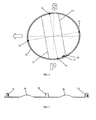
- Figure 6 shows the sensor array 1 in position in a typical wind turbine blade 21.
- the view in Figure 6 is a cross section of the base of the turbine blade 21 viewed from the hub of the wind turbine towards the tip of the turbine blade 21.
- the direction of travel of the turbine blade is indicated by the large arrow and suction side of the blade aerofoil is indicated by the large letter S and the pressure side of the blade aerofoil is indicated by the large letter P.
- the turbine blade 21 is constructed as a surface shell 22 mounted about a structural box beam 23.
- the sensor array is mounted to the internal surface of the shell 22 to form a circumferential ring.
- the sensor support panels 2a - 2d are aligned in their respective positions and then secured in place with glass fibre cloth and epoxy resin. A silica-rich resin is applied to the connecting members 3a - 3c to adhere them to the inner blade surface. Alternatively, the sensor support panels may be embedded in the shell 22.
- the first sensor support panel 2a and the associated strain sensor 7 and temperature sensor 10 are located on the pressure side of the turbine blade 21.
- the third sensor support panel 2c and the associated strain sensor 7 and temperature sensor 10 are located on the suction side of the turbine blade 21.
- the second sensor support panel 2b and the associated strain sensor 7 are located on the leading edge of the turbine blade 21.
- the fourth sensor support panel 2c and the associated strain sensor 7 are located on the trailing edge of the turbine blade 21.
- the sensors are located off the axes of the turbine blade 21 to avoid the sensors 7 being located on the seam of the two blade halves and so that the sensors are aligned with the direction of travel of the blade 21 in typical operating position of the blade, i.e. with 10 to 20 degrees of rotation, for maximum accuracy and minimum crosstalk.
- the connector box 19 is mounted to the inner surface of the turbine blade 21.
- the turbine blade 21 includes a lightning conductor 24 and it will be seen that the sensor array 1 is arranged such that the array 1 does not cross the lightning conductor 24.
- the circumferential spacing between the sensor support panels 2a - 2d is less than the nominal 1.8m.
- the flexibility of the connecting members 3a - 3c allows them to flex, as indicated in Figure 7 , in order that the sensor support panels 2a - 2d are located in the correct positions. In this way, manufacturing tolerances can be accommodated while maintaining the accuracy of the sensor locations.
- the connecting members 3a - 3c are able to roll about their longitudinal axes (and onto their side) to provide additional flexibility in the transverse direction.
- the invention has been described in relation to a sensor array in which all of the sensor support panels extend from the same side of the connecting members, this is not necessary.
- successive sensor support panels may extend from the alternating sides of the connecting members.
- the strain sensors in the described embodiment run transversely to the longitudinal direction of the connecting members, it is possible for the strain sensors to be arranged parallel to the longitudinal direction of the connecting members. Furthermore, it is not necessary for the sensor support panels and the connecting members to be arranged at right angles and other angles are possible.
- an optical fibre strain sensor array comprises several sensor support panels spaced in its longitudinal direction and at least one connecting member extending in the longitudinal direction, which mechanically interconnects the sensor support panels.
- An optical fibre is supported by the sensor support panels and the connecting member.
- the optical fibre extends with the connecting member between the sensor support panels and forms a curve on the sensor support panel, the curve including at least one portion of the optical fibre that extends in the transverse direction.
- the width of the connecting member is substantially less than the width of the sensor support panels, such that the connecting member is capable of flexure in the transverse direction.
Landscapes
- Physics & Mathematics (AREA)
- General Physics & Mathematics (AREA)
- Chemical & Material Sciences (AREA)
- Analytical Chemistry (AREA)
- Optical Transform (AREA)
- Length Measuring Devices By Optical Means (AREA)
- Wind Motors (AREA)
Claims (12)
- Dehnungssensor-Array für Lichtwellenleiter, das über eine Längsrichtung und über eine Querrichtung verfügt, das Array umfassend:eine Mehrzahl von Sensorträgerplatten, die in der Längsrichtung mit Abstand zueinander angeordnet sind und in der Querrichtung eine Breite haben;mindestens ein Verbindungselement, das in der Längsrichtung verläuft und eine Breite in der Querrichtung hat, wobei das bzw. jedes Verbindungselement die Sensorträgerplatten mechanisch miteinander verbindet;einen Lichtwellenleiter, der von den Sensorträgerplatten und dem bzw. jedem Verbindungselement getragen wird;wobei der Lichtwellenleiter mit dem bzw. jedem Verbindungselement zwischen den Sensorträgerplatten verläuft und eine Kurve auf der Sensorträgerplatte bildet,wobei die Kurve mindestens einen Abschnitt des Lichtwellenleiters enthält, der in der Querrichtung verläuft; undwobei die Breite des bzw. jedes Verbindungselements im Wesentlichen geringer ist als die Breite der Sensorträgerplatten, wodurch das bzw. jedes Verbindungselement zur Biegung in der Querrichtung in der Lage ist, und dadurch gekennzeichnet, dass :die Breite der Sensorträgerplatte mehr als das 5fache der Breite des bzw. jedes Verbindungselements beträgt.
- Dehnungssensor-Array für Lichtwellenleiter gemäß Anspruch 1, wobei der Abschnitt des Lichtwellenleiters, der in der Querrichtung verläuft, einen Dehnungssensor für Lichtwellenleiter enthält.
- Dehnungssensor-Array für Lichtwellenleiter gemäß einem der vorherigen Ansprüche, wobei die Sensorträgerplatte in der Richtung, die senkrecht zu sowohl der Quer- als auch der Längsrichtung ist, dünner ist als das bzw. jedes Verbindungselement.
- Dehnungssensor-Array für Lichtwellenleiter gemäß einem der vorherigen Ansprüche, wobei die mindestens eine Sensorträgerplatte eine Temperaturkompensationseinrichtung in Form eines Gehäuses umfasst, welches den Lichtwellenleiter umgibt und an jedem Ende des Gehäuses an dem Lichtwellenleiter befestigt ist, wobei die Länge des Lichtwellenleiters innerhalb des Gehäuses größer als der Abstand zwischen den Enden des Gehäuses ist.
- Dehnungssensor-Array für Lichtwellenleiter gemäß Anspruch 4, wobei das Gehäuse aus einer Basis und einer Abdeckung gebildet wird, wodurch der Lichtwellenleiter während der Herstellung innerhalb des Gehäuses positioniert werden kann, indem der Lichtwellenleiter auf der Basis platziert und die Abdeckung befestigt wird.
- Dehnungssensor-Array für Lichtwellenleiter gemäß Anspruch 4 oder 5, wobei der Abschnitt des Lichtwellenleiters innerhalb des Gehäuses einen Dehnungssensor für Lichtwellenleiter umfasst.
- Dehnungssensor-Array für Lichtwellenleiter gemäß einem der vorherigen Ansprüche, wobei die Sensorträgerplatte(n) und/oder das bzw. die Verbindungselemente aus Schichten aus Glasfasern bestehen, wobei der Lichtwellenleiter zwischen den Schichten liegt.
- Dehnungssensor-Array für Lichtwellenleiter gemäß einem der vorherigen Ansprüche, wobei die Breite der Sensorträgerplatte mehr als das 10fache der Breite des bzw. jedes Verbindungselements beträgt.
- Dehnungssensor-Array für Lichtwellenleiter gemäß Anspruch 8, wobei die Breite der Sensorträgerplatte mehr als das 25fache der Breite des bzw. jedes Verbindungselements beträgt.
- Dehnungssensor-Array für Lichtwellenleiter gemäß einem der vorherigen Ansprüche, wobei die Länge des bzw. jedes Verbindungselements mehr als das 10fache der Breite des bzw. jedes Verbindungselements beträgt.
- Dehnungssensor-Array für Lichtwellenleiter gemäß Anspruch 10, wobei die Breite der Sensorträgerplatte mehr als das 50fache der Breite des bzw. jedes Verbindungselements beträgt.
- Dehnungssensor-Array für Lichtwellenleiter gemäß Anspruch 11, wobei die Breite der Sensorträgerplatte mehr als das 250fache der Breite des bzw. jedes Verbindungselements beträgt.
Applications Claiming Priority (2)
| Application Number | Priority Date | Filing Date | Title |
|---|---|---|---|
| GB0721617A GB2454252B (en) | 2007-11-02 | 2007-11-02 | Sensor array |
| PCT/GB2008/051026 WO2009056892A1 (en) | 2007-11-02 | 2008-11-03 | Sensor array |
Publications (2)
| Publication Number | Publication Date |
|---|---|
| EP2210075A1 EP2210075A1 (de) | 2010-07-28 |
| EP2210075B1 true EP2210075B1 (de) | 2014-05-07 |
Family
ID=38834795
Family Applications (1)
| Application Number | Title | Priority Date | Filing Date |
|---|---|---|---|
| EP08845485.5A Active EP2210075B1 (de) | 2007-11-02 | 2008-11-03 | Sensorarray |
Country Status (6)
| Country | Link |
|---|---|
| US (1) | US8336389B2 (de) |
| EP (1) | EP2210075B1 (de) |
| DK (1) | DK2210075T3 (de) |
| ES (1) | ES2480948T3 (de) |
| GB (1) | GB2454252B (de) |
| WO (1) | WO2009056892A1 (de) |
Families Citing this family (1)
| Publication number | Priority date | Publication date | Assignee | Title |
|---|---|---|---|---|
| GB2454253B (en) * | 2007-11-02 | 2011-02-16 | Insensys Ltd | Strain sensors |
Family Cites Families (14)
| Publication number | Priority date | Publication date | Assignee | Title |
|---|---|---|---|---|
| US5649035A (en) * | 1995-11-03 | 1997-07-15 | Simula Inc. | Fiber optic strain gauge patch |
| EP1148947B1 (de) * | 1999-01-08 | 2006-10-25 | Applera Corporation | Fasermatrix zum zusammenbringen von chemischen stoffen, sowie verfahren zur herstellung und anwendung davon |
| JP2001296110A (ja) * | 2000-04-17 | 2001-10-26 | Ntt Advanced Technology Corp | 貼り付け型光ファイバセンサ |
| US20020181844A1 (en) * | 2000-06-28 | 2002-12-05 | Vaganov Vladimir I. | Optical switch |
| US6668105B2 (en) * | 2000-07-27 | 2003-12-23 | Systems Planning & Analysis, Inc. | Fiber optic strain sensor |
| US6480645B1 (en) * | 2001-01-30 | 2002-11-12 | Tellium, Inc. | Sidewall electrodes for electrostatic actuation and capacitive sensing |
| NO334515B1 (no) * | 2002-03-13 | 2014-03-31 | Light Structures As | Fiberoptisk sensorpakke |
| US7138621B2 (en) * | 2002-05-08 | 2006-11-21 | Virginia Tech Intellectual Properties, Inc. | Optical fiber sensors based on pressure-induced temporal periodic variations in refractive index |
| FR2864202B1 (fr) * | 2003-12-22 | 2006-08-04 | Commissariat Energie Atomique | Dispositif tubulaire instrumente pour le transport d'un fluide sous pression |
| EP1709416B1 (de) * | 2004-01-23 | 2018-03-07 | LM Wind Power International Technology II ApS | Vorrichtung mit einer dehnungsmessvorrichtung mit temperaturabgleich zur dehnungsmessung in faserverstärkten strukturen |
| BRPI0404127B1 (pt) | 2004-09-29 | 2016-02-10 | Petroleo Brasileiro Sa | transdutor de posição a fibra óptica para válvula de controle de vazão em poços inteligentes |
| US7482924B1 (en) * | 2004-11-05 | 2009-01-27 | Tamper Proof Container Licensing Corp. | Cargo container security system communications |
| CA2600888A1 (en) | 2005-03-10 | 2006-09-14 | Commonwealth Scientific And Industrial Research Organisation | Temperature compensating bragg grating optical device |
| EP1869413A1 (de) * | 2005-04-05 | 2007-12-26 | Agency for Science, Technology and Research | Faser-bragg-gitter-sensor |
-
2007
- 2007-11-02 GB GB0721617A patent/GB2454252B/en active Active
-
2008
- 2008-11-03 ES ES08845485.5T patent/ES2480948T3/es active Active
- 2008-11-03 DK DK08845485.5T patent/DK2210075T3/da active
- 2008-11-03 WO PCT/GB2008/051026 patent/WO2009056892A1/en not_active Ceased
- 2008-11-03 EP EP08845485.5A patent/EP2210075B1/de active Active
- 2008-11-03 US US12/741,043 patent/US8336389B2/en not_active Expired - Fee Related
Also Published As
| Publication number | Publication date |
|---|---|
| GB2454252A (en) | 2009-05-06 |
| US8336389B2 (en) | 2012-12-25 |
| EP2210075A1 (de) | 2010-07-28 |
| GB0721617D0 (en) | 2007-12-12 |
| US20100307257A1 (en) | 2010-12-09 |
| GB2454252B (en) | 2010-02-17 |
| DK2210075T3 (da) | 2014-07-14 |
| WO2009056892A1 (en) | 2009-05-07 |
| ES2480948T3 (es) | 2014-07-29 |
Similar Documents
| Publication | Publication Date | Title |
|---|---|---|
| US8161822B2 (en) | Placement of strain sensors in wind turbine blade | |
| US8814514B2 (en) | Embedded fibre optic sensor for wind turbine components | |
| US20100232961A1 (en) | Fibre optic sensors | |
| EP2659253B1 (de) | Vorrichtung und verfahren zur bestimmung der last einer windturbinenschaufel | |
| US9399983B2 (en) | Wind turbine blade with cross-sectional sensors | |
| GB2440954A (en) | Optical monitoring of wind turbine blades | |
| EP1672351B1 (de) | Herstellungsverfahren für die Herstellung eines modularen Sensors zur Schadensdetektion | |
| EP3361093B1 (de) | Verfahren zur detektion von schäden an windturbinenschaufeln und windturbinen | |
| CN103502789B (zh) | 用于确定风力涡轮机叶片的载荷的方法和装置 | |
| JP4626535B2 (ja) | テープ状光ファイバケーブル | |
| DK2590803T3 (en) | Wind turbine blade temperature measurement system and method for producing wind turbine blades | |
| EP2210075B1 (de) | Sensorarray | |
| US20100101335A1 (en) | Strain sensors | |
| WO2015080222A1 (ja) | 歪みセンサ及び歪みセンサの製造方法 | |
| US20110214508A1 (en) | Monitoring the structural integrity of a wind turbine blade | |
| Volanthen et al. | Development of a Practical Optical Fibre System for Health Monitoring Composite Structures |
Legal Events
| Date | Code | Title | Description |
|---|---|---|---|
| PUAI | Public reference made under article 153(3) epc to a published international application that has entered the european phase |
Free format text: ORIGINAL CODE: 0009012 |
|
| 17P | Request for examination filed |
Effective date: 20100528 |
|
| AK | Designated contracting states |
Kind code of ref document: A1 Designated state(s): AT BE BG CH CY CZ DE DK EE ES FI FR GB GR HR HU IE IS IT LI LT LU LV MC MT NL NO PL PT RO SE SI SK TR |
|
| AX | Request for extension of the european patent |
Extension state: AL BA MK RS |
|
| DAX | Request for extension of the european patent (deleted) | ||
| RIN1 | Information on inventor provided before grant (corrected) |
Inventor name: ANGUS, ROBERT, ALLAN Inventor name: VOLANTHEN, MARK |
|
| RAP1 | Party data changed (applicant data changed or rights of an application transferred) |
Owner name: MOOG INSENSYS LIMITED |
|
| 17Q | First examination report despatched |
Effective date: 20131031 |
|
| GRAP | Despatch of communication of intention to grant a patent |
Free format text: ORIGINAL CODE: EPIDOSNIGR1 |
|
| 17Q | First examination report despatched |
Effective date: 20131031 |
|
| INTG | Intention to grant announced |
Effective date: 20140108 |
|
| GRAP | Despatch of communication of intention to grant a patent |
Free format text: ORIGINAL CODE: EPIDOSNIGR1 |
|
| INTG | Intention to grant announced |
Effective date: 20140217 |
|
| GRAS | Grant fee paid |
Free format text: ORIGINAL CODE: EPIDOSNIGR3 |
|
| GRAA | (expected) grant |
Free format text: ORIGINAL CODE: 0009210 |
|
| AK | Designated contracting states |
Kind code of ref document: B1 Designated state(s): AT BE BG CH CY CZ DE DK EE ES FI FR GB GR HR HU IE IS IT LI LT LU LV MC MT NL NO PL PT RO SE SI SK TR |
|
| REG | Reference to a national code |
Ref country code: GB Ref legal event code: FG4D |
|
| REG | Reference to a national code |
Ref country code: AT Ref legal event code: REF Ref document number: 667039 Country of ref document: AT Kind code of ref document: T Effective date: 20140515 |
|
| REG | Reference to a national code |
Ref country code: IE Ref legal event code: FG4D |
|
| REG | Reference to a national code |
Ref country code: DE Ref legal event code: R096 Ref document number: 602008032163 Country of ref document: DE Effective date: 20140618 |
|
| REG | Reference to a national code |
Ref country code: DK Ref legal event code: T3 Effective date: 20140707 |
|
| REG | Reference to a national code |
Ref country code: ES Ref legal event code: FG2A Ref document number: 2480948 Country of ref document: ES Kind code of ref document: T3 Effective date: 20140729 |
|
| REG | Reference to a national code |
Ref country code: NL Ref legal event code: T3 |
|
| REG | Reference to a national code |
Ref country code: AT Ref legal event code: MK05 Ref document number: 667039 Country of ref document: AT Kind code of ref document: T Effective date: 20140507 |
|
| REG | Reference to a national code |
Ref country code: LT Ref legal event code: MG4D |
|
| PG25 | Lapsed in a contracting state [announced via postgrant information from national office to epo] |
Ref country code: LT Free format text: LAPSE BECAUSE OF FAILURE TO SUBMIT A TRANSLATION OF THE DESCRIPTION OR TO PAY THE FEE WITHIN THE PRESCRIBED TIME-LIMIT Effective date: 20140507 Ref country code: NO Free format text: LAPSE BECAUSE OF FAILURE TO SUBMIT A TRANSLATION OF THE DESCRIPTION OR TO PAY THE FEE WITHIN THE PRESCRIBED TIME-LIMIT Effective date: 20140807 Ref country code: GR Free format text: LAPSE BECAUSE OF FAILURE TO SUBMIT A TRANSLATION OF THE DESCRIPTION OR TO PAY THE FEE WITHIN THE PRESCRIBED TIME-LIMIT Effective date: 20140808 Ref country code: IS Free format text: LAPSE BECAUSE OF FAILURE TO SUBMIT A TRANSLATION OF THE DESCRIPTION OR TO PAY THE FEE WITHIN THE PRESCRIBED TIME-LIMIT Effective date: 20140907 Ref country code: CY Free format text: LAPSE BECAUSE OF FAILURE TO SUBMIT A TRANSLATION OF THE DESCRIPTION OR TO PAY THE FEE WITHIN THE PRESCRIBED TIME-LIMIT Effective date: 20140507 Ref country code: FI Free format text: LAPSE BECAUSE OF FAILURE TO SUBMIT A TRANSLATION OF THE DESCRIPTION OR TO PAY THE FEE WITHIN THE PRESCRIBED TIME-LIMIT Effective date: 20140507 |
|
| PG25 | Lapsed in a contracting state [announced via postgrant information from national office to epo] |
Ref country code: HR Free format text: LAPSE BECAUSE OF FAILURE TO SUBMIT A TRANSLATION OF THE DESCRIPTION OR TO PAY THE FEE WITHIN THE PRESCRIBED TIME-LIMIT Effective date: 20140507 Ref country code: SE Free format text: LAPSE BECAUSE OF FAILURE TO SUBMIT A TRANSLATION OF THE DESCRIPTION OR TO PAY THE FEE WITHIN THE PRESCRIBED TIME-LIMIT Effective date: 20140507 Ref country code: LV Free format text: LAPSE BECAUSE OF FAILURE TO SUBMIT A TRANSLATION OF THE DESCRIPTION OR TO PAY THE FEE WITHIN THE PRESCRIBED TIME-LIMIT Effective date: 20140507 Ref country code: AT Free format text: LAPSE BECAUSE OF FAILURE TO SUBMIT A TRANSLATION OF THE DESCRIPTION OR TO PAY THE FEE WITHIN THE PRESCRIBED TIME-LIMIT Effective date: 20140507 Ref country code: PL Free format text: LAPSE BECAUSE OF FAILURE TO SUBMIT A TRANSLATION OF THE DESCRIPTION OR TO PAY THE FEE WITHIN THE PRESCRIBED TIME-LIMIT Effective date: 20140507 |
|
| PG25 | Lapsed in a contracting state [announced via postgrant information from national office to epo] |
Ref country code: PT Free format text: LAPSE BECAUSE OF FAILURE TO SUBMIT A TRANSLATION OF THE DESCRIPTION OR TO PAY THE FEE WITHIN THE PRESCRIBED TIME-LIMIT Effective date: 20140908 |
|
| PG25 | Lapsed in a contracting state [announced via postgrant information from national office to epo] |
Ref country code: EE Free format text: LAPSE BECAUSE OF FAILURE TO SUBMIT A TRANSLATION OF THE DESCRIPTION OR TO PAY THE FEE WITHIN THE PRESCRIBED TIME-LIMIT Effective date: 20140507 Ref country code: SK Free format text: LAPSE BECAUSE OF FAILURE TO SUBMIT A TRANSLATION OF THE DESCRIPTION OR TO PAY THE FEE WITHIN THE PRESCRIBED TIME-LIMIT Effective date: 20140507 Ref country code: CZ Free format text: LAPSE BECAUSE OF FAILURE TO SUBMIT A TRANSLATION OF THE DESCRIPTION OR TO PAY THE FEE WITHIN THE PRESCRIBED TIME-LIMIT Effective date: 20140507 Ref country code: RO Free format text: LAPSE BECAUSE OF FAILURE TO SUBMIT A TRANSLATION OF THE DESCRIPTION OR TO PAY THE FEE WITHIN THE PRESCRIBED TIME-LIMIT Effective date: 20140507 |
|
| REG | Reference to a national code |
Ref country code: DE Ref legal event code: R097 Ref document number: 602008032163 Country of ref document: DE |
|
| PLBE | No opposition filed within time limit |
Free format text: ORIGINAL CODE: 0009261 |
|
| STAA | Information on the status of an ep patent application or granted ep patent |
Free format text: STATUS: NO OPPOSITION FILED WITHIN TIME LIMIT |
|
| 26N | No opposition filed |
Effective date: 20150210 |
|
| PG25 | Lapsed in a contracting state [announced via postgrant information from national office to epo] |
Ref country code: IT Free format text: LAPSE BECAUSE OF FAILURE TO SUBMIT A TRANSLATION OF THE DESCRIPTION OR TO PAY THE FEE WITHIN THE PRESCRIBED TIME-LIMIT Effective date: 20140507 |
|
| REG | Reference to a national code |
Ref country code: DE Ref legal event code: R097 Ref document number: 602008032163 Country of ref document: DE Effective date: 20150210 |
|
| PG25 | Lapsed in a contracting state [announced via postgrant information from national office to epo] |
Ref country code: LU Free format text: LAPSE BECAUSE OF FAILURE TO SUBMIT A TRANSLATION OF THE DESCRIPTION OR TO PAY THE FEE WITHIN THE PRESCRIBED TIME-LIMIT Effective date: 20141103 Ref country code: MC Free format text: LAPSE BECAUSE OF FAILURE TO SUBMIT A TRANSLATION OF THE DESCRIPTION OR TO PAY THE FEE WITHIN THE PRESCRIBED TIME-LIMIT Effective date: 20140507 |
|
| REG | Reference to a national code |
Ref country code: CH Ref legal event code: PL |
|
| PG25 | Lapsed in a contracting state [announced via postgrant information from national office to epo] |
Ref country code: CH Free format text: LAPSE BECAUSE OF NON-PAYMENT OF DUE FEES Effective date: 20141130 Ref country code: LI Free format text: LAPSE BECAUSE OF NON-PAYMENT OF DUE FEES Effective date: 20141130 Ref country code: SI Free format text: LAPSE BECAUSE OF FAILURE TO SUBMIT A TRANSLATION OF THE DESCRIPTION OR TO PAY THE FEE WITHIN THE PRESCRIBED TIME-LIMIT Effective date: 20140507 |
|
| REG | Reference to a national code |
Ref country code: IE Ref legal event code: MM4A |
|
| PG25 | Lapsed in a contracting state [announced via postgrant information from national office to epo] |
Ref country code: IE Free format text: LAPSE BECAUSE OF NON-PAYMENT OF DUE FEES Effective date: 20141103 |
|
| REG | Reference to a national code |
Ref country code: FR Ref legal event code: PLFP Year of fee payment: 8 |
|
| PG25 | Lapsed in a contracting state [announced via postgrant information from national office to epo] |
Ref country code: BG Free format text: LAPSE BECAUSE OF FAILURE TO SUBMIT A TRANSLATION OF THE DESCRIPTION OR TO PAY THE FEE WITHIN THE PRESCRIBED TIME-LIMIT Effective date: 20140507 |
|
| PG25 | Lapsed in a contracting state [announced via postgrant information from national office to epo] |
Ref country code: TR Free format text: LAPSE BECAUSE OF FAILURE TO SUBMIT A TRANSLATION OF THE DESCRIPTION OR TO PAY THE FEE WITHIN THE PRESCRIBED TIME-LIMIT Effective date: 20140507 Ref country code: HU Free format text: LAPSE BECAUSE OF FAILURE TO SUBMIT A TRANSLATION OF THE DESCRIPTION OR TO PAY THE FEE WITHIN THE PRESCRIBED TIME-LIMIT; INVALID AB INITIO Effective date: 20081103 Ref country code: MT Free format text: LAPSE BECAUSE OF FAILURE TO SUBMIT A TRANSLATION OF THE DESCRIPTION OR TO PAY THE FEE WITHIN THE PRESCRIBED TIME-LIMIT Effective date: 20140507 |
|
| REG | Reference to a national code |
Ref country code: FR Ref legal event code: PLFP Year of fee payment: 9 |
|
| REG | Reference to a national code |
Ref country code: FR Ref legal event code: PLFP Year of fee payment: 10 |
|
| PGFP | Annual fee paid to national office [announced via postgrant information from national office to epo] |
Ref country code: NL Payment date: 20191120 Year of fee payment: 12 |
|
| PGFP | Annual fee paid to national office [announced via postgrant information from national office to epo] |
Ref country code: BE Payment date: 20191120 Year of fee payment: 12 |
|
| REG | Reference to a national code |
Ref country code: NL Ref legal event code: MM Effective date: 20201201 |
|
| REG | Reference to a national code |
Ref country code: BE Ref legal event code: MM Effective date: 20201130 |
|
| PG25 | Lapsed in a contracting state [announced via postgrant information from national office to epo] |
Ref country code: NL Free format text: LAPSE BECAUSE OF NON-PAYMENT OF DUE FEES Effective date: 20201201 |
|
| PG25 | Lapsed in a contracting state [announced via postgrant information from national office to epo] |
Ref country code: BE Free format text: LAPSE BECAUSE OF NON-PAYMENT OF DUE FEES Effective date: 20201130 |
|
| PGFP | Annual fee paid to national office [announced via postgrant information from national office to epo] |
Ref country code: DE Payment date: 20251222 Year of fee payment: 18 |
|
| PGFP | Annual fee paid to national office [announced via postgrant information from national office to epo] |
Ref country code: GB Payment date: 20251215 Year of fee payment: 18 |
|
| PGFP | Annual fee paid to national office [announced via postgrant information from national office to epo] |
Ref country code: DK Payment date: 20251216 Year of fee payment: 18 |
|
| PGFP | Annual fee paid to national office [announced via postgrant information from national office to epo] |
Ref country code: FR Payment date: 20251215 Year of fee payment: 18 |
|
| PGFP | Annual fee paid to national office [announced via postgrant information from national office to epo] |
Ref country code: ES Payment date: 20251222 Year of fee payment: 18 |