EP2210128B1 - Dispositif d'insonification qui inclut un réseau tridimensionnel d'émetteurs agencés en au moins deux spirales concentriques et conçus pour générer un faisceau d'ondes focalisées de haute intensité - Google Patents
Dispositif d'insonification qui inclut un réseau tridimensionnel d'émetteurs agencés en au moins deux spirales concentriques et conçus pour générer un faisceau d'ondes focalisées de haute intensité Download PDFInfo
- Publication number
- EP2210128B1 EP2210128B1 EP08850938A EP08850938A EP2210128B1 EP 2210128 B1 EP2210128 B1 EP 2210128B1 EP 08850938 A EP08850938 A EP 08850938A EP 08850938 A EP08850938 A EP 08850938A EP 2210128 B1 EP2210128 B1 EP 2210128B1
- Authority
- EP
- European Patent Office
- Prior art keywords
- transducers
- spirals
- dimensional
- spiral
- insonification
- Prior art date
- Legal status (The legal status is an assumption and is not a legal conclusion. Google has not performed a legal analysis and makes no representation as to the accuracy of the status listed.)
- Active
Links
Images



Classifications
-
- G—PHYSICS
- G01—MEASURING; TESTING
- G01S—RADIO DIRECTION-FINDING; RADIO NAVIGATION; DETERMINING DISTANCE OR VELOCITY BY USE OF RADIO WAVES; LOCATING OR PRESENCE-DETECTING BY USE OF THE REFLECTION OR RERADIATION OF RADIO WAVES; ANALOGOUS ARRANGEMENTS USING OTHER WAVES
- G01S15/00—Systems using the reflection or reradiation of acoustic waves, e.g. sonar systems
- G01S15/88—Sonar systems specially adapted for specific applications
- G01S15/89—Sonar systems specially adapted for specific applications for mapping or imaging
-
- G—PHYSICS
- G01—MEASURING; TESTING
- G01S—RADIO DIRECTION-FINDING; RADIO NAVIGATION; DETERMINING DISTANCE OR VELOCITY BY USE OF RADIO WAVES; LOCATING OR PRESENCE-DETECTING BY USE OF THE REFLECTION OR RERADIATION OF RADIO WAVES; ANALOGOUS ARRANGEMENTS USING OTHER WAVES
- G01S15/00—Systems using the reflection or reradiation of acoustic waves, e.g. sonar systems
- G01S15/88—Sonar systems specially adapted for specific applications
- G01S15/89—Sonar systems specially adapted for specific applications for mapping or imaging
- G01S15/8906—Short-range imaging systems; Acoustic microscope systems using pulse-echo techniques
- G01S15/8909—Short-range imaging systems; Acoustic microscope systems using pulse-echo techniques using a static transducer configuration
- G01S15/8929—Short-range imaging systems; Acoustic microscope systems using pulse-echo techniques using a static transducer configuration using a three-dimensional transducer configuration
-
- G—PHYSICS
- G10—MUSICAL INSTRUMENTS; ACOUSTICS
- G10K—SOUND-PRODUCING DEVICES; METHODS OR DEVICES FOR PROTECTING AGAINST, OR FOR DAMPING, NOISE OR OTHER ACOUSTIC WAVES IN GENERAL; ACOUSTICS NOT OTHERWISE PROVIDED FOR
- G10K11/00—Methods or devices for transmitting, conducting or directing sound in general; Methods or devices for protecting against, or for damping, noise or other acoustic waves in general
- G10K11/18—Methods or devices for transmitting, conducting or directing sound
- G10K11/26—Sound-focusing or directing, e.g. scanning
- G10K11/32—Sound-focusing or directing, e.g. scanning characterised by the shape of the source
-
- G—PHYSICS
- G01—MEASURING; TESTING
- G01S—RADIO DIRECTION-FINDING; RADIO NAVIGATION; DETERMINING DISTANCE OR VELOCITY BY USE OF RADIO WAVES; LOCATING OR PRESENCE-DETECTING BY USE OF THE REFLECTION OR RERADIATION OF RADIO WAVES; ANALOGOUS ARRANGEMENTS USING OTHER WAVES
- G01S7/00—Details of systems according to groups G01S13/00, G01S15/00, G01S17/00
- G01S7/52—Details of systems according to groups G01S13/00, G01S15/00, G01S17/00 of systems according to group G01S15/00
- G01S7/52017—Details of systems according to groups G01S13/00, G01S15/00, G01S17/00 of systems according to group G01S15/00 particularly adapted to short-range imaging
- G01S7/52046—Techniques for image enhancement involving transmitter or receiver
- G01S7/52047—Techniques for image enhancement involving transmitter or receiver for elimination of side lobes or of grating lobes; for increasing resolving power
Definitions
- This present invention relates to the general area of insonification devices that are designed to generate a beam of focussed waves, especially in the ultrasound frequency domain.
- Such insonification devices are used to perform the imaging of an environment or a medium, or indeed to modify the properties of this environment.
- an insonification device according to the invention can be used to raise the temperature of a very precise zone corresponding to the focus zone, where one wishes to focus the beam of ultrasound waves.
- These devices can be used in particular not only in the medical field but also in the areas of underwater imaging and communication, imaging of the terrestrial subsoil, or indeed in the area of non-destructive testing of materials.
- N ultrasound sources that are controlled independently in phase and in amplitude by electronic means, so that their overall energy reaches a local maximum in a predetermined focus zone.
- the positioning of the transducers, in relation to the environment, and in relation to the focus zone, is important since it ensures the effectiveness and the safety of the action performed by virtue of the insonification device, to image or to modify the properties of the environment.
- the field diffracted by all of the transducers can be modified significantly in accordance with the positioning of the transducers and their geometry.
- the three-dimensional concave area is used to perform pre-focussing prior to the additional electronic focussing that will then be performed by applying individually calculated phase delays to each transducer.
- This application of phase delays is commonly employed in the ultrasound area.
- Such heterogeneity of the pressure field generally leads to the appearance of acoustic energy maxima, also called “hot spots”. These maxima can be large at the entry of the ultrasound beam into the environment, and can give rise to irreversible and undesirable damage to the environment or to its surface. They can also be the source of parasitic waves returned by the environment during imaging of the latter.
- the side lobes appear whenever the transducers, which are not infinitely small, are separated by a distance greater than some fractions of wavelengths.
- the main aim of this present invention is to overcome the drawbacks of the known insonification devices by proposing a device for the insonification of an environment, which is designed to generate a beam of focussed waves around a point in a so-called focus zone, this being used for imaging of the environment or changing the properties of the environment, where the insonification device includes an intrinsic or extrinsic support structure on which is installed a network of at least ten ultrasound transducers that are designed to be controlled independently for generation of the focussed beam of waves according to claim 1.
- the distribution of the transducers in a spiral has the advantage of not creating symmetry, while still providing a generally regular distribution in which it is easy to control the distances between the transducers.
- the use of a spiral to distribute the transducers allows one to achieve an insonification that has no undesirable hot spots in the near field, while also enabling one to achieve optimum focussing of the beam at a predetermined focal length, since it is supported by the three-dimensional character of the device itself.
- geometrical pre-focussing enables one to obtain a large antenna gain and to optimise the intensity of the ultrasound beam at the focal point.
- This geometrical pre-focussing is performed by positioning the transducers on a three-dimensional surface, and in particular on a potion of a sphere whose centre coincides with the focal point, or on a portion of an ellipsoid of revolution.
- the homogeneity of the spatial distribution of the transducers is important in order to ensure effectiveness, and to guarantee the operational safety of the insonification device according to the invention, which means that a homogeneous spatial distribution of the mean energy over the three-dimensional concave area must in fact be achieved.
- the homogeneity of the spatial distribution of the transducers is ensured by several parameters, namely the pitch of the spiral, the distance between two consecutive transducers on a given spiral and between two spirals, the number of transducers to be distributed, the size of the insonification device, and the nature of the projection performed if the device is designed from a flat spiral.
- the homogeneous spatial distribution of the transducers therefore ensures a spatially homogeneous distribution of energy on average over the three-dimensional concave area.
- homogeneous spatial distribution of the transducers is meant the fact that their spatial density is homogeneous over the three-dimensional surface.
- homogeneity on average can be taken as meaning on a scale greater than that of the individual transducer.
- the three-dimensional surface is a portion of a sphere whose radius is equal to the wanted focal length.
- Such a characteristic is just what is needed in order to achieve a focus in the three-dimensional concave area, which is particularly simple and effective, since the focus zone that is natural in relation to the geometry of the device is then the centre of the sphere.
- the number of spirals on which the transducers are distributed is between two and twenty and, preferably, between seven and thirteen spirals.
- the spirals are arranged in a plane.
- projection can also be used.
- one or more Archimedes spirals is employed, and when the three-dimensional concave area has a pronounced concave side, the projection is then preferably stereographic.
- An orthogonal projection can be advantageous whenever the concave side is not very pronounced.
- the spirals can be spherical in form, determined directly on a sphere.
- this characteristic means that the spiral is not deformed during projection onto the three-dimensional surface.
- the invention is implemented by means of an extrinsic support structure.
- This structure then includes a three-dimensional concave area according to the characteristics of the invention, and on which the transducers are placed by inserting into orifices provided for this purpose.
- the transducers can then be controlled independently and individually.
- the orifices are created through the extrinsic support structure, following the trajectory of one or more spirals, as specified in the invention.
- the support structure is intrinsic, and is composed of a piezoelectric or semiconductor material whose surface is three-dimensional and concave, where the piezoelectric or semiconductor material is divided into a multiplicity of independent transducer elements of which only some, located along at least two spirals wound onto the three-dimensional concave area of the piezoelectric or semiconductor material, are activated in order to create the focussed beam.
- an insonification device directly from a standard or semiconductor piezoelectric material, such as a Capacitive Micromachined Ultrasonic Transducer (CMUT) device for example, which one will have formed on a three-dimensional concave area specifically designed for optimal focussing of the wave beam at a wanted focal length.
- CMUT Capacitive Micromachined Ultrasonic Transducer
- the invention then consists of activating only a certain number of zones of the transducer, which are composed of a material such as piezoelectric or semiconductor substances, so as to constitute elementary transducers, with these zones of the piezoelectric material being located along two or more spirals in accordance with the principle of the invention.
- the minimum distance between any two transducers is advantageously of the order of the wavelength of the radiation emitted by the device.
- the size of the three-dimensional concave area is determined according to the minimum size of the focal footprint wanted around the focus point.
- the given number of transducers employed, of a given dimension is generally restricted to the number of electronic channels available to control them individually, their density will be inversely proportional to the size of the three-dimensional concave area over which they are distributed.
- the size of the three-dimensional concave area is directly correlated to the minimum size of focal footprint wanted around the focus point.
- the choice of the size of the insonification device in accordance with the size of the focal footprint wanted is a characteristic that needs to be protected, and it is particularly important in the particular context where a limited number of independent commands can be delivered.
- the distribution of the transducers along the spirals having been determined, their position, central or lateral, in relation to the geometrical curve formed by the spirals, is determined randomly and independently for each transducer on either side of the geometrical curve of each spiral in a geometrical segment perpendicular to the curve of the spiral and of a length that is less than or equal to the wavelength.
- the positioning of the transducers in a corridor surrounding the linear structure of the imaginary spirals used to distribute the transducers, and the random character of this positioning of the transducers, is used to introduce an additional particularly advantageous break in the symmetry.
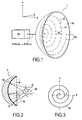
- Figure 1 represents a first embodiment of an insonification device 1 illustrating the principle of the invention but with a simplified drawing that does not correspond to the invention.
- This insonification device 1 includes a three-dimensional concave area 10 in the form of a portion of a sphere, with centre O, on which is wound a spiral 11, along which are placed N transducers 12 at regular intervals.
- the concave side of the three-dimensional concave area 10 is oriented toward a so-called natural focus zone of the insonification device 1, which here is the zone that is equidistant from all the transducers 12, meaning the zone surrounding the centre O of the sphere supporting the three-dimensional concave area 10.
- each transducer 12 gives rise to a more-or-less conical pressure field.
- each transducer 12 With each transducer 12 being placed on the sphere-shaped three-dimensional concave area 10, they are all oriented toward the centre O of this sphere and therefore generate a maximum pressure field in the vicinity of this point O. A focus zone 20 is thus created around this focal point O.
- the geometry of the insonification device 1 is therefore particularly appropriate for insonification of this focus zone 20.
- this focus zone 20 is located in relation to the insonification device 1 is chosen beforehand, and the curvature, or, here, the radius R, of the three-dimensional concave area 10 is then chosen in accordance with a wanted focal length during the design of the insonification device 1.
- the well-known techniques of introducing individually-calculated phase delays into the signals emitted by each of the transducers 12 can be used to move the zone of maximum pressure in the vicinity of the natural focus zone 20, represented in figure 2 .
- Certain latitude is then provided by the insonification device 1, in order to move the zone of maximum pressure on the Z axis and/or on the X and Y axes.
- the movements of the zone of maximum pressure along the OX, OY and OZ axes correspondent to the creation of an electronic steering of the beam of focussed waves.
- the insonification device 1 is connected to a control module 13.
- This control module 13 includes a number N of electronic channels, each designed to individually control one of the N transducers 12 of the insonification device 1 represented in figure 1 .
- each transducer 12 is generally controllable in phase ⁇ and in amplitude A, the control module 13 is therefore designed to send N signals, namely S1(A, ⁇ ) to SN(A, ⁇ ).
- the number N of independent electronic channels available at the date of submission of the patent application is 512 in general. Nevertheless, the principle of the invention remains valid whatever this number N may be, even if it is increased in the future as long as the distance between two transducers is not less than one wavelength.
- the distance between the transducers is generally greater than one wavelength, since it is necessary to use quite wide transducers in order to generate sufficiently high ultrasound energy at the focal point with a limited number of transducers.
- transducers then have sizes that are greater than a few wavelengths of the central emission frequency, and their centres are therefore separated at least by their size, which is greater than the wavelength of the central emission frequency.
- the transducers concerned by the invention are of a characteristic size that is greater than two wavelengths at the central emission frequency.
- transducers with a diameter of 6 mm can be used, which already corresponds to four times the wavelength when the transducers are operating with a frequency of 1 MHz in water or soft tissue.
- Figure 3 proposes an example of a flat spiral 30 of constant pitch. These spirals are known as Archimedes spirals or Archimedes screws. In such a spiral, the distance d between two consecutive points determined by the intersection of an axis (OX) or (OY) with the spiral 30, is always constant.
- the N transducers 12 are then distributed along this spiral 30.
- the number N of transducers 12 is generally determined from the number of independent electronic channels provided by the control module 13.
- the distance between two consecutive transducers 12 on the spiral is chosen so as to comply with the minimum physical distance between the two transducers 12 and a homogeneous distribution of the transducers 12 over the three-dimensional surface 10.
- This homogeneous distribution takes into account the pitch a of the spiral 30 which determines the minimum distance observed between two transducers 12 supported by two successive turns of the spiral 30 on a given straight line passing through the centre of the spiral 30.
- the pitch of the spiral 30, as well as the distribution of the transducers 12 along this spiral 30, is therefore determined in accordance with the overall size of the insonification device 1 and the number N of transducers that can be controlled independently.
- the latter are advantageously separated from each other by a distance that is constant and identical over the entire three-dimensional surface. This means that the pitch of the spiral is more-or-less the same as the distance separating two consecutive transducers 12 supported by the spiral 30.
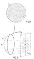
- Figure 5 presents the principle of an orthogonal projection onto a three-dimensional concave area 10 in the form of a spherical cap. It can then be seen that the central zone ZC of the spherical cap and the peripheral zone ZP then necessarily have distinct concentrations of transducers 12.
- the central part of the spherical cap ZC will have a high concentration of transducers 12, while the peripheral part ZP will have transducers 12 that are more distant, since the turns of the spiral 30 move away from each other during projection.
- the concentration of transducers 12 on the periphery is therefore lower. This inhomogeneity of distribution of the transducers 12 leads to a concentration of the energy emitted at the central zone ZC of the spherical cap.
- the accumulation of energy at the central zone ZC can cause damage to the environment or to the surface of the latter. In fact it is possible to observe zones where the intensity of received energy causes heating at the surface of the environment that is located in the near field of the device 1.
- the spiral 30 of figure 3 can also be projected according to an inverse stereographic projection onto the three-dimensional concave area 10.
- the point of reference of the projection is then advantageously chosen to be located on the sphere that includes the three-dimensional concave area 10.
- the stereographic projection results in a better distribution of the transducers 12 between the central part ZC and the peripheral part ZP of the three-dimensional concave area 10.
- a spherical spiral 60 is used directly to place the transducers 12 on the three-dimensional concave area 10 in the form of a portion of a sphere of the insonification device 1.
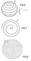
- Figure 6 presents a Clelia spiral 60.
- the equation of this spiral 60 corresponds to the movement of a point M rotating at a constant speed around the polar axis of a sphere on the surface of the latter.
- x, y and z are the rectangular coordinates of the point M
- R is the radius of the sphere
- ⁇ is the angle of the point M in the XOY plane
- m is a parameter used to determine the overall appearance of the volume obtained.
- parameter m is chosen so as to be able to create a spherical spiral.
- this spherical spiral 60 corresponding to the portion of a sphere in figure 1 , is then used to place the N transducers 12.
- the surface distribution of the transducers 12 then obtained is quite uniform between the central part ZC and the peripheral part ZP of the sphere portion.
- the distance between two successive turns of the spiral are then effectively constant when one follows a perimeter of the sphere passing through the centre of the spiral 60 while it increases in the case of projection of the flat spiral 30 on the three-dimensional surface 10.
- a flat spiral of power angle equation can be used so as to obtain a flat spiral 70 that is expanded at the centre and tightened up at the periphery.
- the pitch of the spherical spiral obtained can be substantially constant, and thus results in a homogeneous distribution over the three-dimensional concave area 10.
- the choice of parameters a and b enables one to precisely match the shape of the spiral 70 to the curvature of the three-dimensional concave area 10.
- the distribution of the transducers 12 according to the principle of the invention which is along a three-dimensional spiral, has the advantage of generating no symmetry, while also allowing a regular and homogeneous distribution of the transducers. In this distribution, it is possible to control the distances between the transducers 12 with the pitch of the spiral and the distance between any two consecutive transducers 12 on the spiral.
- Figure 8 represents an embodiment of the invention.
- two concentric spirals are used to determine the distribution of the N transducers 12.
- the two spirals are symmetrical in relation to a vertical axis and therefore start their windings at 180° with respect to each other.
- the use of these two spirals, according to the invention recentres the centre of gravity of the overall energy emitted by the insonification device of figure 4 , for a given number of transducers.
- each of the types of spirals mentioned previously namely flat, derived from various equations and projections, or spherical.
- the start angle of the spirals, as well as their pitch, are designed so that they do not overlap and in order to obtain a homogeneous distribution of the transducers, with the distance between two consecutive transducers 12 on a given spiral being more-or-less equal to the distance between the adjacent turns of the two spirals.
- Figure 9 shows the characteristics of the near field for three types of distribution of the transducers 12 in a single spiral 1S, in a semi-random distribution QR and in a double spiral 2S according to the invention.
- the curves represent the energy E observed as a function of the distance to the focal point DF.
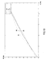
- Figure 10 represents the maximum relative power PR of the lobes observed in the focal plane, in decibels in relation to the amplitude of the pressure at the focal point, in accordance with angulation A, on the Oy axis for example, expressed in mm.
- These relative powers PR correspond to three implementations, two according to the prior art and one according to the simplified implementation as presented on figure 1 . The first corresponds to the case of a device supporting transducers that are arranged in an annular manner AN, and the second to the case where the transducers are arranged on a single spiral 1S, and the third to the case where the transducers are arranged in a semi-random manner.
- the number of concentric spirals is increased.
- the increase in the number of spirals over which the transducers are distributed leads to a spatially more homogeneous distribution of the energy. This has an unexpected, significant and pronounced effect on the magnitude of the secondary lobes.
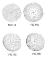
- Figures 11a and 11b respectively represent four Archimedes spirals and four power angle spirals that are concentric and equidistant from each other. In order to create the insonification device according to the invention, these spirals are then projected onto the three-dimensional concave area 10 and the transducers are placed along these spirals.
- Figures 11c and 11d respectively represent, in perspective, four concentric spherical Clelia spirals that have the same distance between them, and the distribution of a network of N transducers on these four spirals.
- N 512 transducers placed along eleven concentric spirals.
- the eleven concentric spirals are obtained by orthogonal projection of eleven Archimedes spirals onto the three-dimensional concave area.
- the insonification device of figure 12a has an overall diameter of 180 mm, while the insonification device of figure 12b has an overall diameter of 300 mm. Their radii of curvature are identical. Since the number of transducers is identical in each case, due to the projection and the increase in the surface, they are therefore more distant overall from each other in figure 12b than in figure 12a .
- Figure 13 represents the distribution of energy in the near field for an insonification device with a single spiral 1S, and which has a semi-random distribution QR of the transducers 12, a distribution of the transducers in seven spirals 7S, in eleven spirals 11S, and in sixteen spirals 16S. It can be seen that the reduction in the secondary lobes is more pronounced for the insonification devices that have a distribution of the transducers on eleven spirals 11S or on sixteen spirals 16S. It can also be seen that the energy is in fact better distributed in these last two cases.
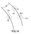
- Figure 14 illustrates this characteristic. This figure represents two portions of turns of a spiral 30.
- the theoretical positions of the transducers 12i, 12i+1, 12j is determined on the trajectory of the spirals in order to create a homogeneous spatial distribution of the transducers, and represented by crosses, the actual position of the transducers is determined randomly in the surface formed by a disk C12i, C12i+1, C12j whose centre is determined by the theoretical placements of the transducers.
- the radius of the disk is of the order of the wavelength of the waves emitted by the transducers in the focussing environment.
- the latitude of random positioning of the transducers on either side of the spiral is limited to one wavelength on each side of the linear structure of the spiral.
- This characteristic introduces an additional rupture of symmetry which is beneficial from the viewpoint of the spatial distribution of the energy emitted by the insonification device. It turns out that this symmetry break produces a more pronounced result as the angulation of the beam increases. In fact, the appearance in the near field of symmetrical lobes of the beam, in relation to the natural focal axis of the insonification device, is then limited.
Landscapes
- Engineering & Computer Science (AREA)
- Physics & Mathematics (AREA)
- Radar, Positioning & Navigation (AREA)
- Remote Sensing (AREA)
- Acoustics & Sound (AREA)
- Computer Networks & Wireless Communication (AREA)
- General Physics & Mathematics (AREA)
- Multimedia (AREA)
- Surgical Instruments (AREA)
- Transducers For Ultrasonic Waves (AREA)
- Variable-Direction Aerials And Aerial Arrays (AREA)
- Investigating Or Analyzing Materials By The Use Of Ultrasonic Waves (AREA)
Claims (10)
- Dispositif d'insonification (1) d'un milieu, apte à générer un faisceau d'ondes focalisées autour d'un point d'une zone dite de focalisation (20), utile pour l'imagerie du milieu ou la modification de propriétés du milieu, le dispositif d'insonification comportant une structure porteuse intrinsèque ou extrinsèque sur laquelle est installé un réseau d'un nombre prédéfini de transducteurs ultrasonores (12) aptes à être commandés indépendamment pour la génération du faisceau d'ondes focalisé, caractérisé en ce que les transducteurs (12) servant pour la génération du faisceau d'ondes focalisé sont des transducteurs larges présentant des dimensions supérieures à quelques longueurs d'onde et sont situés à intervalles réguliers le long d'au moins deux spirales d'Archimède concentriques (11) planes projetées sur une surface tridimensionnelle concave (10), l'enroulement des spirales et les positions des transducteurs sur les spirales étant choisis afin que la distribution spatiale des transducteurs sur la surface tridimensionnelle soit homogène, la forme et la taille de la surface tridimensionnelle étant aussi choisies pour permettre une focalisation optimale du faisceau à une longueur focale prédéterminée et dont la concavité est tournée vers la zone de focalisation (20).
- Dispositif selon la revendication 1, caractérisé en ce que la surface tridimensionnelle (10) est une portion de sphère de rayon (R) égal à la longueur focale désirée.
- Dispositif selon la revendication 1, caractérisé en ce que le nombre de spirales est compris entre deux et vingt.
- Dispositif selon la revendication 3, caractérisé en ce que le nombre de spirales est compris entre sept et treize spirales.
- Dispositif selon l'une des revendications précédentes, caractérisé en ce que la ou les spirale(s) est(sont) une(des) spirale(s) définie(s) dans un plan.
- Dispositif selon l'une des revendications précédentes, caractérisé en ce que la ou les spirale(s) (11) est(sont) une(des) spirale(s) d'Archimède sphérique(s) définie(s) sur une sphère.
- Dispositif selon la revendication 6, caractérisé en ce que la ou les spirale(s) (11) est(sont) choisie(s) parmi les spirales de Clélia, les courbes tridimensionnelles définies par les coordonnées cartésiennes, ou θ est la variable angulaire et R le rayon de la sphère:

- Dispositif selon l'une des revendications précédentes, caractérisé en ce que la structure est intrinsèque et constituée d'un matériau piézoélectrique ou semi-conducteur dont la surface (10) est tridimensionnelle et concave, le matériau piézoélectrique ou semi-conducteur étant divisé en une pluralité d'éléments transducteurs indépendants dont seuls certains (12), situés le long des au moins deux spirales (11), projetées sur la surface tridimensionnelle concave (10) du matériau piézoélectrique ou semi-conducteur, sont activés pour la réalisation du faisceau focalisé.
- Dispositif selon l'une des revendications précédentes, caractérisé en ce que la taille et la forme de la surface tridimensionnelle concave (10) est déterminée en fonction de la taille minimale et la forme de la tache focale (20) désirée autour du point de focalisation (O).
- Dispositif selon l'une des revendications précédentes, caractérisé en ce que la répartition des transducteurs (12) le long de la ou des spirales (11) étant déterminée, la position du centre des transducteurs (12i) est ajustée aléatoirement dans la surface définie par un disque (C12i) dont le centre est la position initiale du centre du transducteur (12i) préalablement déterminée et le rayon est inférieur ou égal à la longueur d'onde dans le milieu de focalisation.
Applications Claiming Priority (3)
| Application Number | Priority Date | Filing Date | Title |
|---|---|---|---|
| FR0758964A FR2923612B1 (fr) | 2007-11-12 | 2007-11-12 | Dispositif d'insonification comprenant un reseau tridimensionnel d'emetteurs disposes en spirale apte a generer un faisceau d'ondes focalisees de grande intensite |
| US640408P | 2008-01-11 | 2008-01-11 | |
| PCT/EP2008/065419 WO2009062977A1 (fr) | 2007-11-12 | 2008-11-12 | Dispositif d'insonification qui inclut un réseau tridimensionnel d'émetteurs agencés en au moins deux spirales concentriques et conçus pour générer un faisceau d'ondes focalisées de haute intensité |
Publications (2)
| Publication Number | Publication Date |
|---|---|
| EP2210128A1 EP2210128A1 (fr) | 2010-07-28 |
| EP2210128B1 true EP2210128B1 (fr) | 2011-05-11 |
Family
ID=39271290
Family Applications (1)
| Application Number | Title | Priority Date | Filing Date |
|---|---|---|---|
| EP08850938A Active EP2210128B1 (fr) | 2007-11-12 | 2008-11-12 | Dispositif d'insonification qui inclut un réseau tridimensionnel d'émetteurs agencés en au moins deux spirales concentriques et conçus pour générer un faisceau d'ondes focalisées de haute intensité |
Country Status (7)
| Country | Link |
|---|---|
| US (1) | US8649242B2 (fr) |
| EP (1) | EP2210128B1 (fr) |
| CN (1) | CN101855572B (fr) |
| AT (1) | ATE509285T1 (fr) |
| FR (1) | FR2923612B1 (fr) |
| IL (1) | IL205428A (fr) |
| WO (1) | WO2009062977A1 (fr) |
Families Citing this family (60)
| Publication number | Priority date | Publication date | Assignee | Title |
|---|---|---|---|---|
| FR2923612B1 (fr) * | 2007-11-12 | 2011-05-06 | Super Sonic Imagine | Dispositif d'insonification comprenant un reseau tridimensionnel d'emetteurs disposes en spirale apte a generer un faisceau d'ondes focalisees de grande intensite |
| CN102210910B (zh) * | 2010-04-02 | 2013-02-13 | 重庆融海超声医学工程研究中心有限公司 | 一种超声换能器 |
| FR2960789B1 (fr) * | 2010-06-07 | 2013-07-19 | Image Guided Therapy | Transducteur d'ultrasons a usage medical |
| US9221077B2 (en) * | 2012-05-09 | 2015-12-29 | Kolo Technologies, Inc. | CMUT assembly with acoustic window |
| GB2513884B (en) | 2013-05-08 | 2015-06-17 | Univ Bristol | Method and apparatus for producing an acoustic field |
| US9612658B2 (en) | 2014-01-07 | 2017-04-04 | Ultrahaptics Ip Ltd | Method and apparatus for providing tactile sensations |
| GB2530036A (en) | 2014-09-09 | 2016-03-16 | Ultrahaptics Ltd | Method and apparatus for modulating haptic feedback |
| JP6657225B2 (ja) | 2014-12-19 | 2020-03-04 | ユニヴェルシテ ピエール エ マリー キュリー(パリ シス)Universite Pierre Et Marie Curie (Paris Vi) | 脳の治療のための埋め込み型超音波発生治療デバイス、そのようなデバイスを備える装置、及びそのようなデバイスを実装する方法 |
| SG11201706557SA (en) | 2015-02-20 | 2017-09-28 | Ultrahaptics Ip Ltd | Perceptions in a haptic system |
| CN107534810B (zh) | 2015-02-20 | 2019-12-20 | 超级触觉资讯处理有限公司 | 用于提供改进的触觉反馈的方法 |
| WO2016162880A1 (fr) * | 2015-04-10 | 2016-10-13 | Indian Institute Of Technology Madras | Procédé innovant de guide d'ondes ultrasonores pour la détection distribuée et le mesurage de propriétés physiques et chimiques du milieu environnant |
| US10818162B2 (en) * | 2015-07-16 | 2020-10-27 | Ultrahaptics Ip Ltd | Calibration techniques in haptic systems |
| JP2017047180A (ja) * | 2015-09-04 | 2017-03-09 | キヤノン株式会社 | 探触子アレイ、および、該探触子アレイを備えた音響波測定装置。 |
| US20170067994A1 (en) * | 2015-09-04 | 2017-03-09 | Canon Kabushiki Kaisha | Transducer array, and acoustic wave measurement apparatus |
| US11189140B2 (en) | 2016-01-05 | 2021-11-30 | Ultrahaptics Ip Ltd | Calibration and detection techniques in haptic systems |
| JP6783319B2 (ja) | 2016-03-11 | 2020-11-11 | ソルボンヌ・ユニヴェルシテSorbonne Universite | 脊髄の治療および/または脊髄神経の治療のための埋め込み型超音波発生治療デバイス、該デバイスを備える装置、および方法 |
| CA3017916C (fr) | 2016-03-11 | 2023-11-07 | Sorbonne Universite | Dispositif de traitement externe generant des ultrasons pour le traitement de la moelle epiniere et des nerfs rachidiens, appareil comprenant un tel dispositif et methode mettant en oeuvre un tel dispositif |
| FR3051693B1 (fr) | 2016-05-31 | 2018-05-11 | Imasonic | Reseau d'elements transducteurs ultrasonores |
| US10531212B2 (en) | 2016-06-17 | 2020-01-07 | Ultrahaptics Ip Ltd. | Acoustic transducers in haptic systems |
| US10268275B2 (en) | 2016-08-03 | 2019-04-23 | Ultrahaptics Ip Ltd | Three-dimensional perceptions in haptic systems |
| US10755538B2 (en) | 2016-08-09 | 2020-08-25 | Ultrahaptics ilP LTD | Metamaterials and acoustic lenses in haptic systems |
| US10943578B2 (en) | 2016-12-13 | 2021-03-09 | Ultrahaptics Ip Ltd | Driving techniques for phased-array systems |
| US10497358B2 (en) | 2016-12-23 | 2019-12-03 | Ultrahaptics Ip Ltd | Transducer driver |
| US20200282424A1 (en) * | 2017-08-11 | 2020-09-10 | North Carolina State University | Optically transparent micromachined ultrasonic transducer (cmut) |
| US11531395B2 (en) | 2017-11-26 | 2022-12-20 | Ultrahaptics Ip Ltd | Haptic effects from focused acoustic fields |
| WO2019122916A1 (fr) | 2017-12-22 | 2019-06-27 | Ultrahaptics Limited | Réduction au minimum des réponses indésirables dans des systèmes haptiques |
| EP3729417B1 (fr) | 2017-12-22 | 2025-09-10 | Ultrahaptics Ip Ltd | Suivi dans des systèmes haptiques |
| CN110064135B (zh) * | 2018-01-22 | 2024-06-21 | 重庆海扶医疗科技股份有限公司 | 盆腔疾病体外聚焦超声治疗设备 |
| SG11202010752VA (en) | 2018-05-02 | 2020-11-27 | Ultrahaptics Ip Ltd | Blocking plate structure for improved acoustic transmission efficiency |
| US11098951B2 (en) | 2018-09-09 | 2021-08-24 | Ultrahaptics Ip Ltd | Ultrasonic-assisted liquid manipulation |
| EP3847529B1 (fr) * | 2018-09-09 | 2025-06-11 | Ultrahaptics IP Limited | Déclenchement d'événement dans les systèmes multi-élements commandés en phase |
| CN109238185B (zh) * | 2018-09-30 | 2023-06-09 | 江苏省水利科学研究院 | 一种桥墩安全性实时监测系统及监测方法 |
| US11378997B2 (en) | 2018-10-12 | 2022-07-05 | Ultrahaptics Ip Ltd | Variable phase and frequency pulse-width modulation technique |
| CN109356576B (zh) * | 2018-10-23 | 2022-05-03 | 中国石油化工股份有限公司 | 测量平面径向流驱替压力梯度的物模实验装置 |
| KR102141654B1 (ko) * | 2018-11-28 | 2020-08-05 | 재단법인 대구경북첨단의료산업진흥재단 | 송수신 듀얼 모드 집속 초음파 트랜스듀서 및 이를 이용한 미소기포 캐비테이션 이미지 가시화방법 |
| FR3089128B1 (fr) | 2018-11-30 | 2020-12-18 | Carthera | Fenetre acoustique pour l’imagerie et/ou le traitement d’un tissu cerebral |
| US12373033B2 (en) | 2019-01-04 | 2025-07-29 | Ultrahaptics Ip Ltd | Mid-air haptic textures |
| WO2020141330A2 (fr) | 2019-01-04 | 2020-07-09 | Ultrahaptics Ip Ltd | Textures haptiques aériennes |
| US11842517B2 (en) | 2019-04-12 | 2023-12-12 | Ultrahaptics Ip Ltd | Using iterative 3D-model fitting for domain adaptation of a hand-pose-estimation neural network |
| CN110620293B (zh) * | 2019-09-20 | 2021-06-11 | 上海无线电设备研究所 | 一种基于六臂螺旋阵列结构的稀疏阵天线 |
| CN114631139A (zh) | 2019-10-13 | 2022-06-14 | 超飞跃有限公司 | 利用虚拟麦克风进行动态封顶 |
| US11374586B2 (en) | 2019-10-13 | 2022-06-28 | Ultraleap Limited | Reducing harmonic distortion by dithering |
| US11169610B2 (en) | 2019-11-08 | 2021-11-09 | Ultraleap Limited | Tracking techniques in haptic systems |
| US11715453B2 (en) | 2019-12-25 | 2023-08-01 | Ultraleap Limited | Acoustic transducer structures |
| US11816267B2 (en) | 2020-06-23 | 2023-11-14 | Ultraleap Limited | Features of airborne ultrasonic fields |
| US12357273B2 (en) | 2020-08-27 | 2025-07-15 | E-Scopics | Apparatus and method for estimating a velocity of at least one scatterer in a medium |
| US11886639B2 (en) | 2020-09-17 | 2024-01-30 | Ultraleap Limited | Ultrahapticons |
| US12032770B2 (en) | 2020-11-23 | 2024-07-09 | Toyota Motor Engineering & Manufacturing North America, Inc. | Haptic array device and control of focus point height and focus point direction |
| US12517585B2 (en) | 2021-07-15 | 2026-01-06 | Ultraleap Limited | Control point manipulation techniques in haptic systems |
| CN113712631B (zh) * | 2021-09-02 | 2024-05-03 | 南京广慈医疗科技有限公司 | 一种随机分布三维相控阵探头的制备方法 |
| KR102792232B1 (ko) * | 2021-12-29 | 2025-04-08 | 동국대학교 산학협력단 | 초음파 빔의 회전력 제어가 가능한 초음파 변환자 및 이를 이용한 초음파 시스템 |
| CN114652971A (zh) * | 2022-03-18 | 2022-06-24 | 重庆融海超声医学工程研究中心有限公司 | 相控阵换能器阵列的布设方法及相控阵换能器阵列 |
| US12383066B2 (en) | 2022-04-26 | 2025-08-12 | Toyota Motor Engineering & Manufacturing North America, Inc. | Chair with shape memory material-based movement synchronized with visual content |
| CN114740461B (zh) * | 2022-06-07 | 2022-09-02 | 深圳市晟达通讯设备有限公司 | 一种声呐系统、以及用于该声呐系统的水下定位天线 |
| US12270386B2 (en) | 2023-02-16 | 2025-04-08 | Toyota Motor Engineering & Manufacturing North America, Inc. | Shape memory material member-based actuator |
| US12241458B2 (en) | 2023-02-16 | 2025-03-04 | Toyota Motor Engineering & Manufacturing North America, Inc. | Actuator with contracting member |
| US12152570B2 (en) | 2023-02-22 | 2024-11-26 | Toyota Motor Engineering & Manufacturing North America, Inc. | Shape memory material member-based actuator with electrostatic clutch preliminary class |
| US12163507B2 (en) | 2023-02-22 | 2024-12-10 | Toyota Motor Engineering & Manufacturing North America, Inc. | Contracting member-based actuator with clutch |
| US12234811B1 (en) | 2023-08-21 | 2025-02-25 | Toyota Motor Engineering & Manufacturing North America, Inc. | Monitoring a state of a shape memory material member |
| US12589512B2 (en) | 2023-12-28 | 2026-03-31 | Toyota Motor Engineering & Manufacturing North America, Inc. | Shearing tool with closure assist |
Family Cites Families (8)
| Publication number | Priority date | Publication date | Assignee | Title |
|---|---|---|---|---|
| US6205224B1 (en) * | 1996-05-17 | 2001-03-20 | The Boeing Company | Circularly symmetric, zero redundancy, planar array having broad frequency range applications |
| US5713356A (en) * | 1996-10-04 | 1998-02-03 | Optosonics, Inc. | Photoacoustic breast scanner |
| US6279399B1 (en) * | 1998-08-03 | 2001-08-28 | Vingmed Sound A/S | Multi-dimensional transducer array apparatus |
| US6102860A (en) * | 1998-12-24 | 2000-08-15 | Agilent Technologies, Inc. | Ultrasound transducer for three-dimensional imaging |
| GB2347043A (en) * | 1999-02-19 | 2000-08-23 | Imp College Innovations Ltd | Ultrasound transducer arrays |
| US6583768B1 (en) * | 2002-01-18 | 2003-06-24 | The Boeing Company | Multi-arm elliptic logarithmic spiral arrays having broadband and off-axis application |
| WO2005120130A1 (fr) * | 2004-06-03 | 2005-12-15 | Olympus Corporation | Vibrateur ultrasonique du type capacité électrostatique, méthode de fabrication, et sonde ultrasonique du type capacité électrostatique |
| FR2923612B1 (fr) * | 2007-11-12 | 2011-05-06 | Super Sonic Imagine | Dispositif d'insonification comprenant un reseau tridimensionnel d'emetteurs disposes en spirale apte a generer un faisceau d'ondes focalisees de grande intensite |
-
2007
- 2007-11-12 FR FR0758964A patent/FR2923612B1/fr active Active
-
2008
- 2008-11-12 CN CN200880115761.4A patent/CN101855572B/zh active Active
- 2008-11-12 EP EP08850938A patent/EP2210128B1/fr active Active
- 2008-11-12 US US12/742,086 patent/US8649242B2/en not_active Expired - Fee Related
- 2008-11-12 WO PCT/EP2008/065419 patent/WO2009062977A1/fr not_active Ceased
- 2008-11-12 AT AT08850938T patent/ATE509285T1/de not_active IP Right Cessation
-
2010
- 2010-04-29 IL IL205428A patent/IL205428A/en active IP Right Grant
Also Published As
| Publication number | Publication date |
|---|---|
| ATE509285T1 (de) | 2011-05-15 |
| IL205428A (en) | 2013-09-30 |
| IL205428A0 (en) | 2010-12-30 |
| EP2210128A1 (fr) | 2010-07-28 |
| US8649242B2 (en) | 2014-02-11 |
| WO2009062977A1 (fr) | 2009-05-22 |
| US20110051554A1 (en) | 2011-03-03 |
| CN101855572A (zh) | 2010-10-06 |
| FR2923612B1 (fr) | 2011-05-06 |
| HK1149084A1 (zh) | 2011-09-23 |
| FR2923612A1 (fr) | 2009-05-15 |
| CN101855572B (zh) | 2015-09-02 |
Similar Documents
| Publication | Publication Date | Title |
|---|---|---|
| EP2210128B1 (fr) | Dispositif d'insonification qui inclut un réseau tridimensionnel d'émetteurs agencés en au moins deux spirales concentriques et conçus pour générer un faisceau d'ondes focalisées de haute intensité | |
| US7263888B2 (en) | Two dimensional phased arrays for volumetric ultrasonic inspection and methods of use | |
| US6618206B2 (en) | System and method for acoustic imaging at two focal lengths with a single lens | |
| US9199100B2 (en) | Ultrasound transducer for medical use | |
| US6622562B2 (en) | Multi pre-focused annular array for high resolution ultrasound imaging | |
| US6488630B1 (en) | Arrays of quasi-randomly distributed ultrasound transducers | |
| US5706820A (en) | Ultrasonic transducer with reduced elevation sidelobes and method for the manufacture thereof | |
| JP5836537B2 (ja) | ユニモルフ型超音波探触子 | |
| CN103650031B (zh) | 利用表面调制产生聚焦超声波的方法和设备 | |
| US20090270735A1 (en) | Electronic array probe for ultrasonic imaging | |
| JPH0759773A (ja) | 流体流感知装置 | |
| US7559897B2 (en) | Electronic array probe for ultrasonic imaging | |
| US7300403B2 (en) | Wide aperture array design with constrained outer probe dimension | |
| Sarvazyan et al. | A comparative study of systems used for dynamic focusing of ultrasound | |
| US7410464B2 (en) | Wave generating device | |
| Tanter et al. | Focusing through skull with time reversal mirrors. Application to hyperthermia | |
| HK1149084B (en) | An insonification device that includes a three-dimensional network of emitters arranged in at least two concentric spirals, which are designed to generate a beam of high- intensity focussed waves | |
| JPH0419504B2 (fr) | ||
| RU2837967C1 (ru) | Устройство томографирования с помощью сегмента кольцевой антенной решётки | |
| US4430898A (en) | Pulse-echo ultrasound system utilizing conjugate emitting and receiving apertures | |
| Lupien et al. | Ultrasonic phased array inspection of titanium billets | |
| Legg et al. | LOW FREQUENCY HIGHLY DIRECTIONAL AIR COUPLED UL-TRASOUND SENSOR | |
| Lasser et al. | Two-dimensional adaptive control of complex wavefronts | |
| KR20240172859A (ko) | 블록 구조 기반 초음파 변환자 및 이를 이용한 초음파 시스템 | |
| JP2020153770A (ja) | 超音波検査装置 |
Legal Events
| Date | Code | Title | Description |
|---|---|---|---|
| PUAI | Public reference made under article 153(3) epc to a published international application that has entered the european phase |
Free format text: ORIGINAL CODE: 0009012 |
|
| 17P | Request for examination filed |
Effective date: 20100423 |
|
| AK | Designated contracting states |
Kind code of ref document: A1 Designated state(s): AT BE BG CH CY CZ DE DK EE ES FI FR GB GR HR HU IE IS IT LI LT LU LV MC MT NL NO PL PT RO SE SI SK TR |
|
| AX | Request for extension of the european patent |
Extension state: AL BA MK RS |
|
| GRAP | Despatch of communication of intention to grant a patent |
Free format text: ORIGINAL CODE: EPIDOSNIGR1 |
|
| DAX | Request for extension of the european patent (deleted) | ||
| GRAS | Grant fee paid |
Free format text: ORIGINAL CODE: EPIDOSNIGR3 |
|
| GRAA | (expected) grant |
Free format text: ORIGINAL CODE: 0009210 |
|
| AK | Designated contracting states |
Kind code of ref document: B1 Designated state(s): AT BE BG CH CY CZ DE DK EE ES FI FR GB GR HR HU IE IS IT LI LT LU LV MC MT NL NO PL PT RO SE SI SK TR |
|
| REG | Reference to a national code |
Ref country code: GB Ref legal event code: FG4D |
|
| REG | Reference to a national code |
Ref country code: CH Ref legal event code: EP |
|
| REG | Reference to a national code |
Ref country code: IE Ref legal event code: FG4D |
|
| REG | Reference to a national code |
Ref country code: DE Ref legal event code: R096 Ref document number: 602008006928 Country of ref document: DE Effective date: 20110622 |
|
| REG | Reference to a national code |
Ref country code: NL Ref legal event code: T3 |
|
| PG25 | Lapsed in a contracting state [announced via postgrant information from national office to epo] |
Ref country code: NO Free format text: LAPSE BECAUSE OF FAILURE TO SUBMIT A TRANSLATION OF THE DESCRIPTION OR TO PAY THE FEE WITHIN THE PRESCRIBED TIME-LIMIT Effective date: 20110811 Ref country code: LT Free format text: LAPSE BECAUSE OF FAILURE TO SUBMIT A TRANSLATION OF THE DESCRIPTION OR TO PAY THE FEE WITHIN THE PRESCRIBED TIME-LIMIT Effective date: 20110511 Ref country code: PT Free format text: LAPSE BECAUSE OF FAILURE TO SUBMIT A TRANSLATION OF THE DESCRIPTION OR TO PAY THE FEE WITHIN THE PRESCRIBED TIME-LIMIT Effective date: 20110912 Ref country code: SE Free format text: LAPSE BECAUSE OF FAILURE TO SUBMIT A TRANSLATION OF THE DESCRIPTION OR TO PAY THE FEE WITHIN THE PRESCRIBED TIME-LIMIT Effective date: 20110511 |
|
| PG25 | Lapsed in a contracting state [announced via postgrant information from national office to epo] |
Ref country code: BE Free format text: LAPSE BECAUSE OF FAILURE TO SUBMIT A TRANSLATION OF THE DESCRIPTION OR TO PAY THE FEE WITHIN THE PRESCRIBED TIME-LIMIT Effective date: 20110511 Ref country code: FI Free format text: LAPSE BECAUSE OF FAILURE TO SUBMIT A TRANSLATION OF THE DESCRIPTION OR TO PAY THE FEE WITHIN THE PRESCRIBED TIME-LIMIT Effective date: 20110511 Ref country code: LV Free format text: LAPSE BECAUSE OF FAILURE TO SUBMIT A TRANSLATION OF THE DESCRIPTION OR TO PAY THE FEE WITHIN THE PRESCRIBED TIME-LIMIT Effective date: 20110511 Ref country code: CY Free format text: LAPSE BECAUSE OF FAILURE TO SUBMIT A TRANSLATION OF THE DESCRIPTION OR TO PAY THE FEE WITHIN THE PRESCRIBED TIME-LIMIT Effective date: 20110511 Ref country code: AT Free format text: LAPSE BECAUSE OF FAILURE TO SUBMIT A TRANSLATION OF THE DESCRIPTION OR TO PAY THE FEE WITHIN THE PRESCRIBED TIME-LIMIT Effective date: 20110511 Ref country code: ES Free format text: LAPSE BECAUSE OF FAILURE TO SUBMIT A TRANSLATION OF THE DESCRIPTION OR TO PAY THE FEE WITHIN THE PRESCRIBED TIME-LIMIT Effective date: 20110822 Ref country code: GR Free format text: LAPSE BECAUSE OF FAILURE TO SUBMIT A TRANSLATION OF THE DESCRIPTION OR TO PAY THE FEE WITHIN THE PRESCRIBED TIME-LIMIT Effective date: 20110812 Ref country code: SI Free format text: LAPSE BECAUSE OF FAILURE TO SUBMIT A TRANSLATION OF THE DESCRIPTION OR TO PAY THE FEE WITHIN THE PRESCRIBED TIME-LIMIT Effective date: 20110511 Ref country code: IS Free format text: LAPSE BECAUSE OF FAILURE TO SUBMIT A TRANSLATION OF THE DESCRIPTION OR TO PAY THE FEE WITHIN THE PRESCRIBED TIME-LIMIT Effective date: 20110911 |
|
| PG25 | Lapsed in a contracting state [announced via postgrant information from national office to epo] |
Ref country code: EE Free format text: LAPSE BECAUSE OF FAILURE TO SUBMIT A TRANSLATION OF THE DESCRIPTION OR TO PAY THE FEE WITHIN THE PRESCRIBED TIME-LIMIT Effective date: 20110511 Ref country code: CZ Free format text: LAPSE BECAUSE OF FAILURE TO SUBMIT A TRANSLATION OF THE DESCRIPTION OR TO PAY THE FEE WITHIN THE PRESCRIBED TIME-LIMIT Effective date: 20110511 |
|
| PG25 | Lapsed in a contracting state [announced via postgrant information from national office to epo] |
Ref country code: RO Free format text: LAPSE BECAUSE OF FAILURE TO SUBMIT A TRANSLATION OF THE DESCRIPTION OR TO PAY THE FEE WITHIN THE PRESCRIBED TIME-LIMIT Effective date: 20110511 Ref country code: SK Free format text: LAPSE BECAUSE OF FAILURE TO SUBMIT A TRANSLATION OF THE DESCRIPTION OR TO PAY THE FEE WITHIN THE PRESCRIBED TIME-LIMIT Effective date: 20110511 Ref country code: DK Free format text: LAPSE BECAUSE OF FAILURE TO SUBMIT A TRANSLATION OF THE DESCRIPTION OR TO PAY THE FEE WITHIN THE PRESCRIBED TIME-LIMIT Effective date: 20110511 Ref country code: PL Free format text: LAPSE BECAUSE OF FAILURE TO SUBMIT A TRANSLATION OF THE DESCRIPTION OR TO PAY THE FEE WITHIN THE PRESCRIBED TIME-LIMIT Effective date: 20110511 |
|
| PLBE | No opposition filed within time limit |
Free format text: ORIGINAL CODE: 0009261 |
|
| STAA | Information on the status of an ep patent application or granted ep patent |
Free format text: STATUS: NO OPPOSITION FILED WITHIN TIME LIMIT |
|
| 26N | No opposition filed |
Effective date: 20120214 |
|
| PG25 | Lapsed in a contracting state [announced via postgrant information from national office to epo] |
Ref country code: HR Free format text: LAPSE BECAUSE OF FAILURE TO SUBMIT A TRANSLATION OF THE DESCRIPTION OR TO PAY THE FEE WITHIN THE PRESCRIBED TIME-LIMIT Effective date: 20111123 |
|
| REG | Reference to a national code |
Ref country code: DE Ref legal event code: R097 Ref document number: 602008006928 Country of ref document: DE Effective date: 20120214 |
|
| PG25 | Lapsed in a contracting state [announced via postgrant information from national office to epo] |
Ref country code: MC Free format text: LAPSE BECAUSE OF NON-PAYMENT OF DUE FEES Effective date: 20111130 |
|
| REG | Reference to a national code |
Ref country code: IE Ref legal event code: MM4A |
|
| PG25 | Lapsed in a contracting state [announced via postgrant information from national office to epo] |
Ref country code: IE Free format text: LAPSE BECAUSE OF NON-PAYMENT OF DUE FEES Effective date: 20111112 |
|
| PG25 | Lapsed in a contracting state [announced via postgrant information from national office to epo] |
Ref country code: MT Free format text: LAPSE BECAUSE OF FAILURE TO SUBMIT A TRANSLATION OF THE DESCRIPTION OR TO PAY THE FEE WITHIN THE PRESCRIBED TIME-LIMIT Effective date: 20110511 |
|
| PG25 | Lapsed in a contracting state [announced via postgrant information from national office to epo] |
Ref country code: LU Free format text: LAPSE BECAUSE OF NON-PAYMENT OF DUE FEES Effective date: 20111112 |
|
| PG25 | Lapsed in a contracting state [announced via postgrant information from national office to epo] |
Ref country code: BG Free format text: LAPSE BECAUSE OF FAILURE TO SUBMIT A TRANSLATION OF THE DESCRIPTION OR TO PAY THE FEE WITHIN THE PRESCRIBED TIME-LIMIT Effective date: 20110811 |
|
| REG | Reference to a national code |
Ref country code: CH Ref legal event code: PL |
|
| GBPC | Gb: european patent ceased through non-payment of renewal fee |
Effective date: 20121112 |
|
| PG25 | Lapsed in a contracting state [announced via postgrant information from national office to epo] |
Ref country code: LI Free format text: LAPSE BECAUSE OF NON-PAYMENT OF DUE FEES Effective date: 20121130 Ref country code: CH Free format text: LAPSE BECAUSE OF NON-PAYMENT OF DUE FEES Effective date: 20121130 |
|
| PG25 | Lapsed in a contracting state [announced via postgrant information from national office to epo] |
Ref country code: TR Free format text: LAPSE BECAUSE OF FAILURE TO SUBMIT A TRANSLATION OF THE DESCRIPTION OR TO PAY THE FEE WITHIN THE PRESCRIBED TIME-LIMIT Effective date: 20110511 |
|
| PG25 | Lapsed in a contracting state [announced via postgrant information from national office to epo] |
Ref country code: HU Free format text: LAPSE BECAUSE OF FAILURE TO SUBMIT A TRANSLATION OF THE DESCRIPTION OR TO PAY THE FEE WITHIN THE PRESCRIBED TIME-LIMIT Effective date: 20110511 |
|
| PG25 | Lapsed in a contracting state [announced via postgrant information from national office to epo] |
Ref country code: GB Free format text: LAPSE BECAUSE OF NON-PAYMENT OF DUE FEES Effective date: 20121112 Ref country code: HR Free format text: LAPSE BECAUSE OF FAILURE TO SUBMIT A TRANSLATION OF THE DESCRIPTION OR TO PAY THE FEE WITHIN THE PRESCRIBED TIME-LIMIT Effective date: 20110511 |
|
| REG | Reference to a national code |
Ref country code: FR Ref legal event code: PLFP Year of fee payment: 9 |
|
| REG | Reference to a national code |
Ref country code: FR Ref legal event code: PLFP Year of fee payment: 10 |
|
| REG | Reference to a national code |
Ref country code: FR Ref legal event code: PLFP Year of fee payment: 11 |
|
| REG | Reference to a national code |
Ref country code: DE Ref legal event code: R082 Ref document number: 602008006928 Country of ref document: DE Representative=s name: PAUSTIAN & PARTNER PATENTANWAELTE MBB, DE Ref country code: DE Ref legal event code: R082 Ref document number: 602008006928 Country of ref document: DE Representative=s name: BETTEN & RESCH PATENT- UND RECHTSANWAELTE PART, DE |
|
| REG | Reference to a national code |
Ref country code: NL Ref legal event code: HC Owner name: SUPERSONIC IMAGINE; FR Free format text: DETAILS ASSIGNMENT: CHANGE OF OWNER(S), CHANGE OF OWNER(S) NAME; FORMER OWNER NAME: SUPER SONIC IMAGINE Effective date: 20201007 |
|
| REG | Reference to a national code |
Ref country code: DE Ref legal event code: R082 Ref document number: 602008006928 Country of ref document: DE Representative=s name: BETTEN & RESCH PATENT- UND RECHTSANWAELTE PART, DE Ref country code: DE Ref legal event code: R081 Ref document number: 602008006928 Country of ref document: DE Owner name: SUPERSONIC IMAGINE, FR Free format text: FORMER OWNER: SUPER SONIC IMAGINE, AIX-EN-PROVENCE, FR |
|
| REG | Reference to a national code |
Ref country code: DE Ref legal event code: R082 Ref document number: 602008006928 Country of ref document: DE Representative=s name: PAUSTIAN & PARTNER PATENTANWAELTE MBB, DE |
|
| PGFP | Annual fee paid to national office [announced via postgrant information from national office to epo] |
Ref country code: IT Payment date: 20221123 Year of fee payment: 15 |
|
| P01 | Opt-out of the competence of the unified patent court (upc) registered |
Effective date: 20230517 |
|
| PGFP | Annual fee paid to national office [announced via postgrant information from national office to epo] |
Ref country code: NL Payment date: 20241022 Year of fee payment: 17 |
|
| PG25 | Lapsed in a contracting state [announced via postgrant information from national office to epo] |
Ref country code: IT Free format text: LAPSE BECAUSE OF NON-PAYMENT OF DUE FEES Effective date: 20231112 |
|
| PG25 | Lapsed in a contracting state [announced via postgrant information from national office to epo] |
Ref country code: IT Free format text: LAPSE BECAUSE OF NON-PAYMENT OF DUE FEES Effective date: 20231112 |
|
| PGFP | Annual fee paid to national office [announced via postgrant information from national office to epo] |
Ref country code: DE Payment date: 20241022 Year of fee payment: 17 |
|
| PGFP | Annual fee paid to national office [announced via postgrant information from national office to epo] |
Ref country code: FR Payment date: 20241022 Year of fee payment: 17 |
|
| REG | Reference to a national code |
Ref country code: DE Ref legal event code: R082 Ref document number: 602008006928 Country of ref document: DE |