EP2210331B1 - Procédé de liaison de pièces d'un porte-rotor en plusieurs pièces et porte-rotor d'une machine électrique - Google Patents
Procédé de liaison de pièces d'un porte-rotor en plusieurs pièces et porte-rotor d'une machine électrique Download PDFInfo
- Publication number
- EP2210331B1 EP2210331B1 EP08804877A EP08804877A EP2210331B1 EP 2210331 B1 EP2210331 B1 EP 2210331B1 EP 08804877 A EP08804877 A EP 08804877A EP 08804877 A EP08804877 A EP 08804877A EP 2210331 B1 EP2210331 B1 EP 2210331B1
- Authority
- EP
- European Patent Office
- Prior art keywords
- rotor
- parts
- clinching
- rotor hub
- rotor carrier
- Prior art date
- Legal status (The legal status is an assumption and is not a legal conclusion. Google has not performed a legal analysis and makes no representation as to the accuracy of the status listed.)
- Not-in-force
Links
- 238000000034 method Methods 0.000 title claims abstract description 26
- 238000005304 joining Methods 0.000 claims abstract description 8
- 239000000463 material Substances 0.000 claims description 34
- 239000011343 solid material Substances 0.000 claims description 3
- 230000000149 penetrating effect Effects 0.000 abstract 2
- 238000004080 punching Methods 0.000 description 5
- 238000003754 machining Methods 0.000 description 4
- 238000005516 engineering process Methods 0.000 description 3
- 238000004519 manufacturing process Methods 0.000 description 3
- 238000007781 pre-processing Methods 0.000 description 3
- 238000003825 pressing Methods 0.000 description 3
- 230000015572 biosynthetic process Effects 0.000 description 2
- 238000005266 casting Methods 0.000 description 2
- 238000007493 shaping process Methods 0.000 description 2
- 238000003466 welding Methods 0.000 description 2
- 238000000137 annealing Methods 0.000 description 1
- 230000009286 beneficial effect Effects 0.000 description 1
- 230000001419 dependent effect Effects 0.000 description 1
- 238000005553 drilling Methods 0.000 description 1
- 238000003475 lamination Methods 0.000 description 1
- 230000035515 penetration Effects 0.000 description 1
- 238000002203 pretreatment Methods 0.000 description 1
- 230000007704 transition Effects 0.000 description 1
Images

Classifications
-
- H—ELECTRICITY
- H02—GENERATION; CONVERSION OR DISTRIBUTION OF ELECTRIC POWER
- H02K—DYNAMO-ELECTRIC MACHINES
- H02K1/00—Details of the magnetic circuit
- H02K1/06—Details of the magnetic circuit characterised by the shape, form or construction
- H02K1/22—Rotating parts of the magnetic circuit
- H02K1/28—Means for mounting or fastening rotating magnetic parts on to, or to, the rotor structures
- H02K1/30—Means for mounting or fastening rotating magnetic parts on to, or to, the rotor structures using intermediate parts, e.g. spiders
-
- B—PERFORMING OPERATIONS; TRANSPORTING
- B21—MECHANICAL METAL-WORKING WITHOUT ESSENTIALLY REMOVING MATERIAL; PUNCHING METAL
- B21D—WORKING OR PROCESSING OF SHEET METAL OR METAL TUBES, RODS OR PROFILES WITHOUT ESSENTIALLY REMOVING MATERIAL; PUNCHING METAL
- B21D39/00—Application of procedures in order to connect objects or parts, e.g. coating with sheet metal otherwise than by plating; Tube expanders
- B21D39/03—Application of procedures in order to connect objects or parts, e.g. coating with sheet metal otherwise than by plating; Tube expanders of sheet metal otherwise than by folding
- B21D39/031—Joining superposed plates by locally deforming without slitting or piercing
-
- H—ELECTRICITY
- H02—GENERATION; CONVERSION OR DISTRIBUTION OF ELECTRIC POWER
- H02K—DYNAMO-ELECTRIC MACHINES
- H02K15/00—Processes or apparatus specially adapted for manufacturing, assembling, maintaining or repairing of dynamo-electric machines
- H02K15/02—Processes or apparatus specially adapted for manufacturing, assembling, maintaining or repairing of dynamo-electric machines of stator or rotor bodies
-
- Y—GENERAL TAGGING OF NEW TECHNOLOGICAL DEVELOPMENTS; GENERAL TAGGING OF CROSS-SECTIONAL TECHNOLOGIES SPANNING OVER SEVERAL SECTIONS OF THE IPC; TECHNICAL SUBJECTS COVERED BY FORMER USPC CROSS-REFERENCE ART COLLECTIONS [XRACs] AND DIGESTS
- Y10—TECHNICAL SUBJECTS COVERED BY FORMER USPC
- Y10T—TECHNICAL SUBJECTS COVERED BY FORMER US CLASSIFICATION
- Y10T29/00—Metal working
- Y10T29/49—Method of mechanical manufacture
- Y10T29/49002—Electrical device making
- Y10T29/49009—Dynamoelectric machine
Definitions
- the invention relates to a method for connecting parts of a multi-part rotor carrier of an electric machine according to the preamble of claim 1 and such a multi-part rotor carrier.
- rotor carrier In the manufacture of rotors for electric machines today one-piece, forming or casting technology produced rotor carrier are common, which are increasingly being replaced by multi-part Rotoexm due to their technical and, depending on the application, possible economic disadvantages.
- These multi-part rotor carrier can for example consist of a rotor hub, which is produced approximately in pot form, and of a support member applied to this in the form of a cylinder tube section, so that rotor hub and support member are made separately and the support member can be electrically switched, for example, in its entire axial extent, without curvature radii have to be considered at transition into the rotor hub.
- the rotor hub within the support member can be axially displaced or arranged within wide limits relative to the support member, so that there are considerable space advantages and freedom in the design of the arrangement.
- the parts of multi-part rotor carrier, such as the rotor hub and the support member must be rotatably connected to each other to form the rotor carrier, so in such a way that the parts to be joined perform no relative movement to each other.
- WO 2006/017377 A discloses a method for connecting parts of a multi-part rotor carrier of an electric machine, wherein the rotor carrier as a part has a rotor hub and as another part a arranged on the rotor hub support member, wherein the rotor hub and support member are connected by a connection operation with each other in a rotationally fixed.
- EP 0 133 858 A is the clinching known as a possible connection process, with the rotor laminations are connected to each other quickly and inexpensively.
- the US 4,174,559 A shows the connection of two parts of a fan disc by means of clinching. From the WO 2004/004941 A It is known that two circumferentially closed hollow profiles can be connected with a clinching.
- the object of the invention is to provide a method for connecting parts of a multi-part rotor carrier of an electrical machine, which avoids the disadvantages mentioned, and enables a cost-effective and production-optimized production of multi-part rotor carrier.
- the individual parts of the multipart rotor carrier are produced in a manner known from the prior art by forming or casting technology or by machining from solid material.
- the parts are limited to simple and inexpensive to produce parts in this process, especially in large-sized electrical machines, such as those used in electric and hybrid drives.
- These parts are processed in the manner required for this, and then rotatably connected by a connection process.
- As a joining process is a clinching, which is known in the art as Druckhegen, clinching or Toxen as a proven connection technology for sheets. By the clinching, no heat is introduced into the parts to be joined, so that a thermal distortion of the parts is prevented.
- the clinching can be done without introducing additional materials, which is economical and in qualitative Regard is beneficial.
- subsequent processing can be followed by further processing, for example in the form of stress relief annealing and / or further machining to the desired end geometry of the rotor carrier.
- clinching is meant that material of one part in such a way in areas of the other Part is registered, in particular by pressing with suitable press dies, that a positive and positive connection in the joining region of the parts to be joined. Details show the embodiments.
- the clinching takes place in the full material of the parts.
- the parts are therefore not processed in the joining area before the connection process for the purpose of connecting, but the clinching leads to a positive and positive fit of the full material of the parts, ie in particular without pre-drilling, pre-punching or similar at least one of the two parts to be connected pre-treatment pretreatment , It is advantageous that the clinching takes place as a particularly cost-effective, economical connection process, since, as described, eliminates a pretreatment of the parts to be joined in the joint area.
- At least one of the parts in the joining region of the connection point to be produced is pre-machined before the clinching, in particular pre-punched and / or reshaped.
- pre-machining of the joining region may be desirable in order to avoid undesirably high mechanical loads in the joining region, in particular in the case of very large material thicknesses in which it is no longer possible to enforce the full material with the desired accuracy.
- a pre-punching, pre-punching or forming the penetration of the material of one part with material of the other part is facilitated because the connecting operation performing press ram no longer has to reshape several parts in full thickness.
- the press force to be applied is reduced, on the other hand, a better precision of the connection process can be achieved, especially with large material thicknesses.
- a multi-part rotor carrier according to claim 4 is also provided.
- the clinching ridge is made by cold deformation as material passage of the material of the one part with material of the other part by applying force by means of a press ram. An unnecessary heat input and in particular a thermal distortion of the parts to be joined is thereby avoided in an advantageous manner.
- the enforcing point is made of the full material of the parts.
- not particularly large material thickness of one or more parts can be as cost-effective to produce a rotationally fixed connection without much manufacturing effort.
- the at least one part of a shaping or forming in which is pushed by the clinching material of the other part.
- high-cost parts can also be inexpensively connected to one another in the way of clinching without the rotor arm being subjected to undesired heat input due to the previously required welding of the parts.
- shaping or reshaping for example, a form-fitting overlapping or folding over of material of one part can be achieved via material of the other part, so that a very particularly firm, positive connection between the parts to be joined can be achieved.
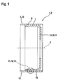
- FIG. 1 shows a rotor carrier 1, namely a two-part rotor carrier 2.
- a rotor hub 3 which is formed substantially in the shape of a pot 4, wherein the pot 4 is a rotary body 5 which is rotationally symmetrical to a rotational axis 6 of the rotor carrier 1 and a substantially parallel to the axis of rotation 6 side wall 7, on the outside 8, a support member 9 of the rotor support 1 is applied to form the two-part rotor support 2, and wherein the support member 9 is formed as a pipe section 10.
- the rotor hub 3 in this case forms one part 11 of the rotor carrier 1, while the supporting part 9 forms the other part 12 of the rotor carrier 1.
- connection point 13 is connected to the other part 12 via at least one connection point 13, which is formed as a passing through point 14.
- material 15 of the one part 11 is introduced into the other part 12, so that the other part 12 is penetrated by material 15 of the one part 11.
- connection point 13 is shown here merely as an example as a single connection point 13.
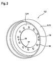
- FIG. 2 shows the rotor arm 1, namely the two-piece rotor arm 2 with the rotor hub 3 as the one part 11 and the rotatably connected to this other part 12, namely the support member 9.
- the rotor hub 3 on its bottom 17 pot mounting recesses 18, which may be combined in particular for correct alignment with Drehausrichtstoffn 19 and / or center holes.
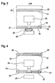
- FIG. 3 shows the method of clinching on a portion 20 of the two-part rotor support 2, namely a simplified plan illustrated side wall portion 21 of the rotor hub 3 and a tube wall portion 22 of the tubular portion 10 formed as a support member 9.
- the clinching can also be done in a different direction than shown here.
- the clinching is performed here without pre-machining the side wall portion 21 and / or the tube wall portion 22 of the full material 23 of both parts, such that a press ram 24 impinges on the full material 23 of the superimposed side wall portions 21 and tube wall portions 22, and this in a form adapted to him Die 25 is transformed into it.
- material 15 of the tube wall section 22 is introduced into material 15 of the side wall section 21, the side wall section 21 consequently penetrated by material 15 of the tube wall section 22.
- the design of the die 25 results in the formation of a projection 26 on the die side of the side wall section 21.
- FIG. 4 shows the clinching in turn on a simplified plan illustrated side wall portion 21 and a tube wall portion 22, wherein the formation of a projection 26 (FIG. FIG. 3 ) should be avoided.
- the press die 24 is in this case in correspondence of the die 25 formed such that a by pressing the full material 23 of the tube wall portion 22 by the full material 23 of the side wall portion 21 effected cantilever does not occur, but a deformation of the side wall portion 21 via a side wall portion 21 facing the die side 27 does not take place.
- the die 25 is preferably planar toward the die side 27.
- FIG. 5 shows the clinching with a side wall portion 21, which has a recess 28, for example a hole punching 29 or a bore 30 after a pre-processing.
- the pipe wall section 22 lying on it is not preprocessed, in particular not pre-punched;
- the press die 24, in cooperation with the die 25, forms a cup-shaped passage 31 of the recess 28 made in the side wall section 21, the projection 26 embracing the recess 28 on the die side and thus good strength the enforcing shank 14 formed in this way is achieved.
- FIG. 6 shows the clinching during preprocessing of both parts, namely the side wall portion 21 and the tube wall portion 22.
- the tube wall portion 22 as well as the side wall portion 21 for this purpose, the recess 28, wherein the recess 28 in the tube wall portion 22 as angled, for example, diagonally cut / countersunk Rohrwandabêtaus Principleung 32 is formed, such that the pipe wall recess on the side wall portion 21 facing away from the side has a larger diameter on the side wall portion 21 facing side.
- the recess 28 is formed in the side wall portion 21 as sowandausnaturalung 33, such that the Sowandausnaturalung 33 was prepared in the course of, for example, a combined punching / forming process and a substantially perpendicular to the plane 34 of the side wall portion 21 projection in the direction of the tube wall portion 22, namely in particular projecting into the pipe wall recess 32 wall projection 35.
- the press ram 24 has, for the further embodiment of the enforcing joint 14, a stamping mandrel 36, for example of a conical or frusto-conical shape, which in the course of the pressing process engages the wall projection 35 via the pipe wall recess 32 presses and this plastically permanently deformed, so that the Wandauskragung 35 pressed into the pipe wall recess 32 non-positively and positively, or is folded.
- a stamping mandrel 36 for example of a conical or frusto-conical shape, which in the course of the pressing process engages the wall projection 35 via the pipe wall recess 32 presses and this plastically permanently deformed, so that the Wandauskragung 35 pressed into the pipe wall recess 32 non-positively and positively, or is folded.
Landscapes
- Engineering & Computer Science (AREA)
- Power Engineering (AREA)
- Mechanical Engineering (AREA)
- Manufacturing & Machinery (AREA)
- Manufacture Of Motors, Generators (AREA)
- Insulation, Fastening Of Motor, Generator Windings (AREA)
- Iron Core Of Rotating Electric Machines (AREA)
Claims (6)
- Procédé pour relier des pièces d'un porte-rotor en plusieurs pièces d'une machine électrique, le porte-rotor présentant, sous forme d'une pièce, un moyeu de rotor, et sous forme d'une autre pièce, une pièce de support disposée sur le moyeu de rotor, le moyeu de rotor et la pièce de support étant reliés l'un à l'autre de manière solidaire en rotation au moyen d'une opération de liaison, caractérisé en ce que l'opération de liaison est un assemblage par agrafage.
- Procédé selon la revendication 1, caractérisé en ce que l'assemblage par agrafage a lieu dans le matériau massif des pièces.
- Procédé selon l'une quelconque des revendications précédentes, caractérisé en ce qu'avant l'assemblage par agrafage, au moins l'une des pièces est prétraitée, notamment préperforée et/ou déformée, dans la zone du joint de l'emplacement d'assemblage à créer.
- Porte-rotor en plusieurs pièces d'une machine électrique, qui présente sous forme d'une pièce, un moyeu de rotor, et sous forme d'une autre pièce, une pièce de support disposée sur le moyeu de rotor, le moyeu de rotor et la pièce de support étant reliés l'un à l'autre de manière solidaire en rotation au moyen d'au moins une opération de liaison, caractérisé en ce que l'on prévoit comme emplacement d'assemblage (13) un emplacement d'assemblage par agrafage (14).
- Porte-rotor selon la revendication 4, caractérisé en ce que l'emplacement d'assemblage par agrafage (14) est créé dans le matériau massif (23) des pièces (11, 12).
- Porte-rotor selon les revendications 4 et 5, caractérisé en ce que l'au moins une pièce (11) présente un préperforage ou une déformation, dans lequel ou laquelle du matériau (15) de l'autre pièce (12) est enfoncé par l'assemblage par agrafage.
Applications Claiming Priority (2)
| Application Number | Priority Date | Filing Date | Title |
|---|---|---|---|
| DE102007049149A DE102007049149A1 (de) | 2007-10-12 | 2007-10-12 | Verfahren zum Verbinden von Teilen eines mehrteiligen Rotorträgers und Rotorträger einer elektrischen Maschine |
| PCT/EP2008/063020 WO2009050027A1 (fr) | 2007-10-12 | 2008-09-29 | Procédé de liaison de pièces d'un porte-rotor en plusieurs pièces et porte-rotor d'une machine électrique |
Publications (2)
| Publication Number | Publication Date |
|---|---|
| EP2210331A1 EP2210331A1 (fr) | 2010-07-28 |
| EP2210331B1 true EP2210331B1 (fr) | 2011-01-19 |
Family
ID=40328846
Family Applications (1)
| Application Number | Title | Priority Date | Filing Date |
|---|---|---|---|
| EP08804877A Not-in-force EP2210331B1 (fr) | 2007-10-12 | 2008-09-29 | Procédé de liaison de pièces d'un porte-rotor en plusieurs pièces et porte-rotor d'une machine électrique |
Country Status (6)
| Country | Link |
|---|---|
| US (1) | US20100213797A1 (fr) |
| EP (1) | EP2210331B1 (fr) |
| CN (1) | CN101821924A (fr) |
| AT (1) | ATE496416T1 (fr) |
| DE (2) | DE102007049149A1 (fr) |
| WO (1) | WO2009050027A1 (fr) |
Cited By (1)
| Publication number | Priority date | Publication date | Assignee | Title |
|---|---|---|---|---|
| DE102019108902A1 (de) * | 2019-04-04 | 2020-10-08 | Benteler Automobiltechnik Gmbh | Batterieträger mit Clinch-Verbindung |
Families Citing this family (2)
| Publication number | Priority date | Publication date | Assignee | Title |
|---|---|---|---|---|
| DE102012008015A1 (de) * | 2012-04-24 | 2013-10-24 | Daimler Ag | Rotorträger und Verfahren zur Herstellung eines Rotorträgers |
| FR3033215B1 (fr) * | 2015-02-26 | 2017-02-24 | Valeo Vision | Prise de courant pour habitacle de vehicule |
Family Cites Families (10)
| Publication number | Priority date | Publication date | Assignee | Title |
|---|---|---|---|---|
| US4174559A (en) * | 1978-02-09 | 1979-11-20 | J.J. & M. | Fastening method |
| EP0133858B1 (fr) * | 1983-08-12 | 1986-09-10 | Essa Fabrique de Machines S.A. | Procédé et dispositif pour fabriquer des paquets composés de lames de tôle pour des noyaux magnétiques de machines électriques |
| US6343773B1 (en) * | 1999-01-21 | 2002-02-05 | Shop Vac Corporation | Support structure |
| DE19915186A1 (de) * | 1999-04-05 | 2000-11-09 | Werner Klaeui | Licht- und Energiesystem für Fahrräder, Motorräder und Mehrradfahrzeuge |
| DE19939528A1 (de) * | 1999-08-20 | 2001-02-22 | Bayerische Motoren Werke Ag | Elektrische Maschine mit einem Rotor und einem Stator |
| DE10230284B4 (de) * | 2002-07-05 | 2008-10-16 | Daimler Ag | Verfahren und Vorrichtung zur Befestigung von Bauteilen an umfänglich geschlossensn Hohlprofilen |
| DE10252130B4 (de) * | 2002-11-04 | 2004-11-25 | Michelin Kronprinz Werke Gmbh | Verfahren zur Herstellung eines Fahrzeugrades |
| FR2855672B1 (fr) * | 2003-05-26 | 2005-08-19 | Valeo Equip Electr Moteur | Dispositif de ventilation, notamment pour alternateur de vehicule automobile |
| US20070152521A1 (en) * | 2004-06-24 | 2007-07-05 | Lg Electronics, Inc | Motor of washing machine |
| US7355309B2 (en) * | 2004-08-06 | 2008-04-08 | Northern Power Systems, Inc. | Permanent magnet rotor for a direct drive generator or a low speed motor |
-
2007
- 2007-10-12 DE DE102007049149A patent/DE102007049149A1/de not_active Ceased
-
2008
- 2008-09-29 AT AT08804877T patent/ATE496416T1/de active
- 2008-09-29 CN CN200880111184A patent/CN101821924A/zh active Pending
- 2008-09-29 EP EP08804877A patent/EP2210331B1/fr not_active Not-in-force
- 2008-09-29 WO PCT/EP2008/063020 patent/WO2009050027A1/fr not_active Ceased
- 2008-09-29 DE DE502008002435T patent/DE502008002435D1/de active Active
- 2008-09-29 US US12/682,395 patent/US20100213797A1/en not_active Abandoned
Cited By (1)
| Publication number | Priority date | Publication date | Assignee | Title |
|---|---|---|---|---|
| DE102019108902A1 (de) * | 2019-04-04 | 2020-10-08 | Benteler Automobiltechnik Gmbh | Batterieträger mit Clinch-Verbindung |
Also Published As
| Publication number | Publication date |
|---|---|
| DE502008002435D1 (de) | 2011-03-03 |
| EP2210331A1 (fr) | 2010-07-28 |
| DE102007049149A1 (de) | 2009-04-16 |
| US20100213797A1 (en) | 2010-08-26 |
| WO2009050027A1 (fr) | 2009-04-23 |
| ATE496416T1 (de) | 2011-02-15 |
| CN101821924A (zh) | 2010-09-01 |
Similar Documents
| Publication | Publication Date | Title |
|---|---|---|
| EP1198309B1 (fr) | Procede, dispositif et piece d'aide a l'assemblage pour realiser un assemblage mecanique | |
| DE19861391B4 (de) | Verfahren zum Formen einer Nabenscheibe und Drückrolle zur Verwendung beim Formen einer Nabenscheibe | |
| WO2006084609A1 (fr) | Procede pour la fixation inamovible d'au moins une piece sur un element de base au moyen d'un boulon plastiquement deforme | |
| EP1886030B1 (fr) | Rivet | |
| WO2014048885A2 (fr) | Pièce de jonction d'aide au soudage et procédé pour relier des éléments à l'aide de cette pièce de jonction d'aide au soudage | |
| EP3690260B1 (fr) | Rivet auto-poinçonneur semi-tubulaire, raccordement riveté d'au moins deux composants à l'aide du rivet auto-poinçonneur semi-tubulaire ainsi que procédé de raccordement des composants au rivet auto-poinçonneur semi-tubulaire | |
| DE102011109815A1 (de) | Verbindung zumindest zweier aneinander anliegender Bauteile | |
| DE102010020569A1 (de) | Verfahren zum thermischen Fügen von zwei Bauelementen | |
| CH704438B1 (de) | Verfahren zur Herstellung einer Nocke für eine Nockenwelle. | |
| EP4144925A1 (fr) | Attelage du véhicule de travail, dispositif de montage sur le véhicule de travail, ensemble et procédé | |
| DE102009044678B4 (de) | Verfahren und Vorrichtung zur Herstellung einer formschlüssigen Verbindung von unterschiedlichen topfförmigen Bauteilen einer Bremstrommel | |
| WO2021228493A1 (fr) | Procédé de fabrication d'un rotor et rotor | |
| EP1368153B1 (fr) | Procede d'assemblage d'un arbre a cames | |
| EP2210331B1 (fr) | Procédé de liaison de pièces d'un porte-rotor en plusieurs pièces et porte-rotor d'une machine électrique | |
| EP2349604B1 (fr) | Procédé de production d'une roue cellulaire | |
| EP2446173B1 (fr) | Structure soudee, notamment porte-satellites, procédé de fabrication cette structure et dispositif d'executer du procédé | |
| DE19849981C5 (de) | Verfahren zum Formen eines scheibenförmigen Teiles mit Nabe und Drückrolle für das Verfahren | |
| EP3054182B1 (fr) | Procédé de fabrication d'une liaison bout à bout entre un boîtier articulé et un composant de liaison et élément de construction fabriqué selon ledit procédé | |
| DE102019208366B4 (de) | Verstellbarer Wankstabilisator für ein Kraftfahrzeug, Gehäuse für einen verstellbaren Wankstabilisator und Verfahren zu dessen Herstellung | |
| EP1763412B1 (fr) | Dispositif de bordage avec un systeme de pivotement | |
| EP0997210B1 (fr) | Procédé de fabrication d'objets en forme de disque avec moyeu et rouleau de pression pour exécuter ledit procédé | |
| DE19643076C2 (de) | Vorrichtung zum in einem Arbeitsgang erfolgenden Stanzen und Fügen mindestens zweier Blechteile | |
| DE102017220816A1 (de) | Fügevorrichtung und verfahren zum fügen mindestens eines bauteils unter verwendung einer x-zange | |
| EP4029626A1 (fr) | Crémaillère et procédé de fabrication d'une crémaillère pour un boîtier de direction d'un véhicule automobile | |
| DE102008007578A1 (de) | Verfahren zur Befestigung eines Lagerschildes an einem Statorblechpaket sowie Stator für einen elektromotorischen Antrieb |
Legal Events
| Date | Code | Title | Description |
|---|---|---|---|
| PUAI | Public reference made under article 153(3) epc to a published international application that has entered the european phase |
Free format text: ORIGINAL CODE: 0009012 |
|
| 17P | Request for examination filed |
Effective date: 20100512 |
|
| AK | Designated contracting states |
Kind code of ref document: A1 Designated state(s): AT BE BG CH CY CZ DE DK EE ES FI FR GB GR HR HU IE IS IT LI LT LU LV MC MT NL NO PL PT RO SE SI SK TR |
|
| AX | Request for extension of the european patent |
Extension state: AL BA MK RS |
|
| GRAP | Despatch of communication of intention to grant a patent |
Free format text: ORIGINAL CODE: EPIDOSNIGR1 |
|
| DAX | Request for extension of the european patent (deleted) | ||
| GRAS | Grant fee paid |
Free format text: ORIGINAL CODE: EPIDOSNIGR3 |
|
| GRAA | (expected) grant |
Free format text: ORIGINAL CODE: 0009210 |
|
| AK | Designated contracting states |
Kind code of ref document: B1 Designated state(s): AT BE BG CH CY CZ DE DK EE ES FI FR GB GR HR HU IE IS IT LI LT LU LV MC MT NL NO PL PT RO SE SI SK TR |
|
| REG | Reference to a national code |
Ref country code: GB Ref legal event code: FG4D Free format text: NOT ENGLISH |
|
| REG | Reference to a national code |
Ref country code: CH Ref legal event code: EP |
|
| REG | Reference to a national code |
Ref country code: IE Ref legal event code: FG4D Free format text: LANGUAGE OF EP DOCUMENT: GERMAN |
|
| REF | Corresponds to: |
Ref document number: 502008002435 Country of ref document: DE Date of ref document: 20110303 Kind code of ref document: P |
|
| REG | Reference to a national code |
Ref country code: DE Ref legal event code: R096 Ref document number: 502008002435 Country of ref document: DE Effective date: 20110303 |
|
| REG | Reference to a national code |
Ref country code: NL Ref legal event code: VDEP Effective date: 20110119 |
|
| LTIE | Lt: invalidation of european patent or patent extension |
Effective date: 20110119 |
|
| PG25 | Lapsed in a contracting state [announced via postgrant information from national office to epo] |
Ref country code: LV Free format text: LAPSE BECAUSE OF FAILURE TO SUBMIT A TRANSLATION OF THE DESCRIPTION OR TO PAY THE FEE WITHIN THE PRESCRIBED TIME-LIMIT Effective date: 20110119 Ref country code: GR Free format text: LAPSE BECAUSE OF FAILURE TO SUBMIT A TRANSLATION OF THE DESCRIPTION OR TO PAY THE FEE WITHIN THE PRESCRIBED TIME-LIMIT Effective date: 20110420 Ref country code: PT Free format text: LAPSE BECAUSE OF FAILURE TO SUBMIT A TRANSLATION OF THE DESCRIPTION OR TO PAY THE FEE WITHIN THE PRESCRIBED TIME-LIMIT Effective date: 20110519 Ref country code: SE Free format text: LAPSE BECAUSE OF FAILURE TO SUBMIT A TRANSLATION OF THE DESCRIPTION OR TO PAY THE FEE WITHIN THE PRESCRIBED TIME-LIMIT Effective date: 20110119 Ref country code: ES Free format text: LAPSE BECAUSE OF FAILURE TO SUBMIT A TRANSLATION OF THE DESCRIPTION OR TO PAY THE FEE WITHIN THE PRESCRIBED TIME-LIMIT Effective date: 20110430 Ref country code: NO Free format text: LAPSE BECAUSE OF FAILURE TO SUBMIT A TRANSLATION OF THE DESCRIPTION OR TO PAY THE FEE WITHIN THE PRESCRIBED TIME-LIMIT Effective date: 20110419 Ref country code: LT Free format text: LAPSE BECAUSE OF FAILURE TO SUBMIT A TRANSLATION OF THE DESCRIPTION OR TO PAY THE FEE WITHIN THE PRESCRIBED TIME-LIMIT Effective date: 20110119 Ref country code: HR Free format text: LAPSE BECAUSE OF FAILURE TO SUBMIT A TRANSLATION OF THE DESCRIPTION OR TO PAY THE FEE WITHIN THE PRESCRIBED TIME-LIMIT Effective date: 20110119 Ref country code: IS Free format text: LAPSE BECAUSE OF FAILURE TO SUBMIT A TRANSLATION OF THE DESCRIPTION OR TO PAY THE FEE WITHIN THE PRESCRIBED TIME-LIMIT Effective date: 20110519 |
|
| REG | Reference to a national code |
Ref country code: IE Ref legal event code: FD4D |
|
| PG25 | Lapsed in a contracting state [announced via postgrant information from national office to epo] |
Ref country code: SI Free format text: LAPSE BECAUSE OF FAILURE TO SUBMIT A TRANSLATION OF THE DESCRIPTION OR TO PAY THE FEE WITHIN THE PRESCRIBED TIME-LIMIT Effective date: 20110119 Ref country code: FI Free format text: LAPSE BECAUSE OF FAILURE TO SUBMIT A TRANSLATION OF THE DESCRIPTION OR TO PAY THE FEE WITHIN THE PRESCRIBED TIME-LIMIT Effective date: 20110119 Ref country code: NL Free format text: LAPSE BECAUSE OF FAILURE TO SUBMIT A TRANSLATION OF THE DESCRIPTION OR TO PAY THE FEE WITHIN THE PRESCRIBED TIME-LIMIT Effective date: 20110119 Ref country code: BG Free format text: LAPSE BECAUSE OF FAILURE TO SUBMIT A TRANSLATION OF THE DESCRIPTION OR TO PAY THE FEE WITHIN THE PRESCRIBED TIME-LIMIT Effective date: 20110419 Ref country code: PL Free format text: LAPSE BECAUSE OF FAILURE TO SUBMIT A TRANSLATION OF THE DESCRIPTION OR TO PAY THE FEE WITHIN THE PRESCRIBED TIME-LIMIT Effective date: 20110119 Ref country code: CY Free format text: LAPSE BECAUSE OF FAILURE TO SUBMIT A TRANSLATION OF THE DESCRIPTION OR TO PAY THE FEE WITHIN THE PRESCRIBED TIME-LIMIT Effective date: 20110119 |
|
| PG25 | Lapsed in a contracting state [announced via postgrant information from national office to epo] |
Ref country code: DK Free format text: LAPSE BECAUSE OF FAILURE TO SUBMIT A TRANSLATION OF THE DESCRIPTION OR TO PAY THE FEE WITHIN THE PRESCRIBED TIME-LIMIT Effective date: 20110119 Ref country code: IE Free format text: LAPSE BECAUSE OF FAILURE TO SUBMIT A TRANSLATION OF THE DESCRIPTION OR TO PAY THE FEE WITHIN THE PRESCRIBED TIME-LIMIT Effective date: 20110119 Ref country code: EE Free format text: LAPSE BECAUSE OF FAILURE TO SUBMIT A TRANSLATION OF THE DESCRIPTION OR TO PAY THE FEE WITHIN THE PRESCRIBED TIME-LIMIT Effective date: 20110119 |
|
| PLBE | No opposition filed within time limit |
Free format text: ORIGINAL CODE: 0009261 |
|
| STAA | Information on the status of an ep patent application or granted ep patent |
Free format text: STATUS: NO OPPOSITION FILED WITHIN TIME LIMIT |
|
| PG25 | Lapsed in a contracting state [announced via postgrant information from national office to epo] |
Ref country code: SK Free format text: LAPSE BECAUSE OF FAILURE TO SUBMIT A TRANSLATION OF THE DESCRIPTION OR TO PAY THE FEE WITHIN THE PRESCRIBED TIME-LIMIT Effective date: 20110119 Ref country code: RO Free format text: LAPSE BECAUSE OF FAILURE TO SUBMIT A TRANSLATION OF THE DESCRIPTION OR TO PAY THE FEE WITHIN THE PRESCRIBED TIME-LIMIT Effective date: 20110119 Ref country code: CZ Free format text: LAPSE BECAUSE OF FAILURE TO SUBMIT A TRANSLATION OF THE DESCRIPTION OR TO PAY THE FEE WITHIN THE PRESCRIBED TIME-LIMIT Effective date: 20110119 |
|
| 26N | No opposition filed |
Effective date: 20111020 |
|
| REG | Reference to a national code |
Ref country code: DE Ref legal event code: R097 Ref document number: 502008002435 Country of ref document: DE Effective date: 20111020 |
|
| BERE | Be: lapsed |
Owner name: ROBERT BOSCH G.M.B.H. Effective date: 20110930 |
|
| PG25 | Lapsed in a contracting state [announced via postgrant information from national office to epo] |
Ref country code: MC Free format text: LAPSE BECAUSE OF NON-PAYMENT OF DUE FEES Effective date: 20110930 |
|
| PG25 | Lapsed in a contracting state [announced via postgrant information from national office to epo] |
Ref country code: BE Free format text: LAPSE BECAUSE OF NON-PAYMENT OF DUE FEES Effective date: 20110930 |
|
| PG25 | Lapsed in a contracting state [announced via postgrant information from national office to epo] |
Ref country code: MT Free format text: LAPSE BECAUSE OF FAILURE TO SUBMIT A TRANSLATION OF THE DESCRIPTION OR TO PAY THE FEE WITHIN THE PRESCRIBED TIME-LIMIT Effective date: 20110119 |
|
| REG | Reference to a national code |
Ref country code: CH Ref legal event code: PL |
|
| PG25 | Lapsed in a contracting state [announced via postgrant information from national office to epo] |
Ref country code: LU Free format text: LAPSE BECAUSE OF NON-PAYMENT OF DUE FEES Effective date: 20110929 |
|
| PG25 | Lapsed in a contracting state [announced via postgrant information from national office to epo] |
Ref country code: LI Free format text: LAPSE BECAUSE OF NON-PAYMENT OF DUE FEES Effective date: 20120930 Ref country code: CH Free format text: LAPSE BECAUSE OF NON-PAYMENT OF DUE FEES Effective date: 20120930 |
|
| PG25 | Lapsed in a contracting state [announced via postgrant information from national office to epo] |
Ref country code: TR Free format text: LAPSE BECAUSE OF FAILURE TO SUBMIT A TRANSLATION OF THE DESCRIPTION OR TO PAY THE FEE WITHIN THE PRESCRIBED TIME-LIMIT Effective date: 20110119 |
|
| PG25 | Lapsed in a contracting state [announced via postgrant information from national office to epo] |
Ref country code: HU Free format text: LAPSE BECAUSE OF FAILURE TO SUBMIT A TRANSLATION OF THE DESCRIPTION OR TO PAY THE FEE WITHIN THE PRESCRIBED TIME-LIMIT Effective date: 20110119 |
|
| REG | Reference to a national code |
Ref country code: AT Ref legal event code: MM01 Ref document number: 496416 Country of ref document: AT Kind code of ref document: T Effective date: 20130929 |
|
| PG25 | Lapsed in a contracting state [announced via postgrant information from national office to epo] |
Ref country code: AT Free format text: LAPSE BECAUSE OF NON-PAYMENT OF DUE FEES Effective date: 20130929 |
|
| REG | Reference to a national code |
Ref country code: FR Ref legal event code: PLFP Year of fee payment: 9 |
|
| REG | Reference to a national code |
Ref country code: FR Ref legal event code: PLFP Year of fee payment: 10 |
|
| REG | Reference to a national code |
Ref country code: FR Ref legal event code: PLFP Year of fee payment: 11 |
|
| PGFP | Annual fee paid to national office [announced via postgrant information from national office to epo] |
Ref country code: DE Payment date: 20191125 Year of fee payment: 12 |
|
| PGFP | Annual fee paid to national office [announced via postgrant information from national office to epo] |
Ref country code: GB Payment date: 20200923 Year of fee payment: 13 Ref country code: FR Payment date: 20200921 Year of fee payment: 13 |
|
| PGFP | Annual fee paid to national office [announced via postgrant information from national office to epo] |
Ref country code: IT Payment date: 20200930 Year of fee payment: 13 |
|
| REG | Reference to a national code |
Ref country code: DE Ref legal event code: R119 Ref document number: 502008002435 Country of ref document: DE |
|
| PG25 | Lapsed in a contracting state [announced via postgrant information from national office to epo] |
Ref country code: DE Free format text: LAPSE BECAUSE OF NON-PAYMENT OF DUE FEES Effective date: 20210401 |
|
| GBPC | Gb: european patent ceased through non-payment of renewal fee |
Effective date: 20210929 |
|
| PG25 | Lapsed in a contracting state [announced via postgrant information from national office to epo] |
Ref country code: GB Free format text: LAPSE BECAUSE OF NON-PAYMENT OF DUE FEES Effective date: 20210929 Ref country code: FR Free format text: LAPSE BECAUSE OF NON-PAYMENT OF DUE FEES Effective date: 20210930 |
|
| PG25 | Lapsed in a contracting state [announced via postgrant information from national office to epo] |
Ref country code: IT Free format text: LAPSE BECAUSE OF NON-PAYMENT OF DUE FEES Effective date: 20210929 |