EP2210841A2 - Convoyeur avec des cames d'alignement - Google Patents
Convoyeur avec des cames d'alignement Download PDFInfo
- Publication number
- EP2210841A2 EP2210841A2 EP09405167A EP09405167A EP2210841A2 EP 2210841 A2 EP2210841 A2 EP 2210841A2 EP 09405167 A EP09405167 A EP 09405167A EP 09405167 A EP09405167 A EP 09405167A EP 2210841 A2 EP2210841 A2 EP 2210841A2
- Authority
- EP
- European Patent Office
- Prior art keywords
- products
- conveyor
- leading
- distance
- conveying
- Prior art date
- Legal status (The legal status is an assumption and is not a legal conclusion. Google has not performed a legal analysis and makes no representation as to the accuracy of the status listed.)
- Withdrawn
Links
- 238000000034 method Methods 0.000 claims abstract description 10
- 230000008878 coupling Effects 0.000 claims description 4
- 238000010168 coupling process Methods 0.000 claims description 4
- 238000005859 coupling reaction Methods 0.000 claims description 4
- 230000014759 maintenance of location Effects 0.000 claims 1
- 238000010586 diagram Methods 0.000 description 6
- 230000008859 change Effects 0.000 description 5
- 238000004806 packaging method and process Methods 0.000 description 4
- 229920001817 Agar Polymers 0.000 description 2
- 230000001133 acceleration Effects 0.000 description 2
- 230000007246 mechanism Effects 0.000 description 2
- 241000282472 Canis lupus familiaris Species 0.000 description 1
- 239000000969 carrier Substances 0.000 description 1
- 238000006243 chemical reaction Methods 0.000 description 1
- 238000010276 construction Methods 0.000 description 1
- 230000001419 dependent effect Effects 0.000 description 1
- 230000000694 effects Effects 0.000 description 1
- 230000002996 emotional effect Effects 0.000 description 1
- 238000005516 engineering process Methods 0.000 description 1
- 238000003754 machining Methods 0.000 description 1
- 239000002184 metal Substances 0.000 description 1
- 230000008569 process Effects 0.000 description 1
- 230000000284 resting effect Effects 0.000 description 1
- 230000000717 retained effect Effects 0.000 description 1
- 230000001360 synchronised effect Effects 0.000 description 1
- 230000007704 transition Effects 0.000 description 1
Images


Classifications
-
- B—PERFORMING OPERATIONS; TRANSPORTING
- B65—CONVEYING; PACKING; STORING; HANDLING THIN OR FILAMENTARY MATERIAL
- B65H—HANDLING THIN OR FILAMENTARY MATERIAL, e.g. SHEETS, WEBS, CABLES
- B65H33/00—Forming counted batches in delivery pile or stream of articles
- B65H33/16—Forming counted batches in delivery pile or stream of articles by depositing articles in batches on moving supports
- B65H33/18—Forming counted batches in delivery pile or stream of articles by depositing articles in batches on moving supports with separators between adjacent batches
-
- B—PERFORMING OPERATIONS; TRANSPORTING
- B65—CONVEYING; PACKING; STORING; HANDLING THIN OR FILAMENTARY MATERIAL
- B65G—TRANSPORT OR STORAGE DEVICES, e.g. CONVEYORS FOR LOADING OR TIPPING, SHOP CONVEYOR SYSTEMS OR PNEUMATIC TUBE CONVEYORS
- B65G17/00—Conveyors having an endless traction element, e.g. a chain, transmitting movement to a continuous or substantially-continuous load-carrying surface or to a series of individual load-carriers; Endless-chain conveyors in which the chains form the load-carrying surface
- B65G17/26—Conveyors having an endless traction element, e.g. a chain, transmitting movement to a continuous or substantially-continuous load-carrying surface or to a series of individual load-carriers; Endless-chain conveyors in which the chains form the load-carrying surface comprising a series of co-operating units, e.g. interconnected by pivots
-
- B—PERFORMING OPERATIONS; TRANSPORTING
- B65—CONVEYING; PACKING; STORING; HANDLING THIN OR FILAMENTARY MATERIAL
- B65G—TRANSPORT OR STORAGE DEVICES, e.g. CONVEYORS FOR LOADING OR TIPPING, SHOP CONVEYOR SYSTEMS OR PNEUMATIC TUBE CONVEYORS
- B65G23/00—Driving gear for endless conveyors; Belt- or chain-tensioning arrangements
- B65G23/24—Gearing between driving motor and belt- or chain-engaging elements
- B65G23/30—Variable-speed gearing
-
- B—PERFORMING OPERATIONS; TRANSPORTING
- B65—CONVEYING; PACKING; STORING; HANDLING THIN OR FILAMENTARY MATERIAL
- B65G—TRANSPORT OR STORAGE DEVICES, e.g. CONVEYORS FOR LOADING OR TIPPING, SHOP CONVEYOR SYSTEMS OR PNEUMATIC TUBE CONVEYORS
- B65G47/00—Article or material-handling devices associated with conveyors; Methods employing such devices
- B65G47/74—Feeding, transfer, or discharging devices of particular kinds or types
- B65G47/84—Star-shaped wheels or devices having endless travelling belts or chains, the wheels or devices being equipped with article-engaging elements
- B65G47/841—Devices having endless travelling belts or chains equipped with article-engaging elements
-
- B—PERFORMING OPERATIONS; TRANSPORTING
- B65—CONVEYING; PACKING; STORING; HANDLING THIN OR FILAMENTARY MATERIAL
- B65H—HANDLING THIN OR FILAMENTARY MATERIAL, e.g. SHEETS, WEBS, CABLES
- B65H31/00—Pile receivers
- B65H31/34—Apparatus for squaring-up piled articles
-
- B—PERFORMING OPERATIONS; TRANSPORTING
- B65—CONVEYING; PACKING; STORING; HANDLING THIN OR FILAMENTARY MATERIAL
- B65H—HANDLING THIN OR FILAMENTARY MATERIAL, e.g. SHEETS, WEBS, CABLES
- B65H2404/00—Parts for transporting or guiding the handled material
- B65H2404/20—Belts
- B65H2404/23—Belts with auxiliary handling means
- B65H2404/232—Blade, plate, finger
-
- B—PERFORMING OPERATIONS; TRANSPORTING
- B65—CONVEYING; PACKING; STORING; HANDLING THIN OR FILAMENTARY MATERIAL
- B65H—HANDLING THIN OR FILAMENTARY MATERIAL, e.g. SHEETS, WEBS, CABLES
- B65H2404/00—Parts for transporting or guiding the handled material
- B65H2404/20—Belts
- B65H2404/28—Other properties of belts
- B65H2404/284—Elasticity
-
- B—PERFORMING OPERATIONS; TRANSPORTING
- B65—CONVEYING; PACKING; STORING; HANDLING THIN OR FILAMENTARY MATERIAL
- B65H—HANDLING THIN OR FILAMENTARY MATERIAL, e.g. SHEETS, WEBS, CABLES
- B65H2404/00—Parts for transporting or guiding the handled material
- B65H2404/30—Chains
- B65H2404/31—Chains with auxiliary handling means
- B65H2404/311—Blades, lugs, plates, paddles, fingers
-
- B—PERFORMING OPERATIONS; TRANSPORTING
- B65—CONVEYING; PACKING; STORING; HANDLING THIN OR FILAMENTARY MATERIAL
- B65H—HANDLING THIN OR FILAMENTARY MATERIAL, e.g. SHEETS, WEBS, CABLES
- B65H2511/00—Dimensions; Position; Numbers; Identification; Occurrences
- B65H2511/10—Size; Dimensions
- B65H2511/11—Length
-
- B—PERFORMING OPERATIONS; TRANSPORTING
- B65—CONVEYING; PACKING; STORING; HANDLING THIN OR FILAMENTARY MATERIAL
- B65H—HANDLING THIN OR FILAMENTARY MATERIAL, e.g. SHEETS, WEBS, CABLES
- B65H2511/00—Dimensions; Position; Numbers; Identification; Occurrences
- B65H2511/20—Location in space
- B65H2511/22—Distance
Definitions
- the invention relates to the field of conveyor technology and more particularly to an apparatus and method for conveying and aligning objects or stacks of flat and optionally also flexible articles such as printed products according to the preamble of the respective independent claims.
- Such a conveying and aligning device is for example off EP 1 410 992 A1 known.
- flat products are fed by means of a conveyor of an automatic packaging machine, wherein a distance between the products selected in advance and then fixed.
- the flat flexible products or partial products are preferably individual printed products, but also CDs, or flat sample objects.
- a stack is formed by stacking. The orientation of the trailing edges of the products of a stack is done by one with the conveyor with moving sliding element ("pusher"), the alignment of the leading edges done by a stop element at one point of the conveyor briefly against the leading edges of the moving in the conveying direction stack is held.
- the stop element is moved away from the direction of movement of the stack, and then again against the front edge of the next stack emotional.
- the device can not prevent the stack from slipping apart after alignment, either because the stacked products slip off each other, or because the conveying movement is decelerated.
- drivers can be leading or trailing driver, which are independently movable by means of an electric linear drive, including magnets are attached to the drivers.
- the distance between leading and trailing dogs is adjustable to unfold a carton blank sandwiched therebetween into a carton. It can also be arranged a leading and a trailing driver on a common carrier.
- DE 33 35 583 A1 shows a feed device for batch shifting of sheet stacks by means of grippers.
- a front gripper and a rear gripper form a gripper pair.
- At least one of the two grippers can be adjustable to adapt to the product.
- the two grippers are arranged on a reciprocally movable driver.
- US 5,072,573 shows a transport tray with in the conveying direction against each other sliding transverse walls. The shift is controlled by a backdrop.
- the conveyor for conveying and aligning products or stacks of flat products has leading cams for abutting a leading edge of the products, and trailing cams or sliding cams for abutting a trailing edge of the products.
- the products can be inserted between the leading and trailing cams and thereby aligned. In this case, a distance between successive sliding cam is adjustable without needing to be replaced parts of the device.
- the distance between successive sliding cams is equal to the distance between the trailing edges of the products, and is also referred to as pitch below. It is thus possible to vary the pitch.
- the pitch can be adapted to the length of the products in the conveying direction. This product length is approximately equal to or slightly less than a shelf length defined by the distance between a leading cam and the subsequent sliding cam. If the pitch were not adjustable, the distance between adjacent products, in the case of shorter length products, would be reduced Also called product distance below, enlarged. However, for processing devices such as packaging machines such as filming machines supplied by the conveyor, it is desirable or required that the product distance be the same regardless of the product length. By the pitch is adaptable, the product spacing can be kept constant even with different product lengths or, more generally, adjusted to a predetermined value regardless of the product length.
- the setting of the device to a different pitch is done without the device dismantled and parts such as conveyor chains with different cam intervals must be replaced. For a quick conversion of the device to different product lengths is possible. However, it may not necessarily be possible to adjust the pitch during operation of the device. In other words, it may be necessary to stop the device to change the pitch.
- a sliding cam and a subsequent leading cam are firmly connected to each other. As a result, they together form a unit called alignment element and are moved together.
- the product distance between successive products or product stacks is determined by the length of the alignment elements in the conveying direction.
- the pitch and the compartment length are determined by the distance of the alignment elements from each other.
- the alignment elements are in one piece, so that their leading surface acts like a sliding cam, and the trailing surface acts as a leading cam.
- the product distance is adjustable.
- This adjustability can be realized, for example, by the alignment elements are each conveyed individually, and thereby have mutually displaceable leading and trailing cams. Their distance becomes for example, controlled by a link control.
- the leading and trailing cams can each be transported independently by their own, separate funding, as described below for the alignment elements.
- the offset between the cams of the separate conveying means can also be predetermined and set.
- the sliding cam to achieve an adjustable distance at regular intervals attached to a rotating conveyor, and the distance by adjusting the length of the conveyor is adjustable.
- the conveying means is designed such that a change in length of the entire conveyor is distributed uniformly and proportionally over the length. The distance between each successive cam thus extends for all cams by the same proportion.
- leading cams and sliding cams can be conveyed by means of a single conveying means.
- the leading cams and the sliding cams are separated from each other as separate parts, they can be conveyed on separate conveyors. They are then promoted out of phase with each other.
- two or more parallel and synchronous cam sets will be present in practice at least for the shift cams and preferably also for the leading cams.
- the circulating conveyor is flexible and elastic and the distance is adjustable by stretching the conveyor.
- the conveyor may be a rope or a belt, or a Group of ropes or straps and be formed for example of a resilient plastic or metal springs, which connect the successive cams together.
- the conveyor runs around, for example, two deflection rollers, the length adjustment being effected by adjusting the distance between the deflection rollers, preferably by displacing a bearing axis of one of the deflection rollers.
- the circulating conveyor is a buffer chain, ie a chain with adjustable distance between the chain links, and the distance is adjustable by control blocks of the conveyor.
- buffer chains or conveyors with controllable distance between individual conveyor elements are for example in the published patents EP 0 300 170 and EP 0 309 702 described.
- the adjustment of the length of the conveying means by changing the length of a linear conveying path, around which the conveyor rotates, ie a conveying path, which runs with a top run (or workstrum) and a return run linearly between two deflecting elements.
- the deflecting elements can be immovable at the end of the conveying path, and the conveying means in the return strand with the cams can be guided around one or more further deflection rollers or tensioning rollers whose axial position is displaceable for adjusting the length of the conveying means.
- the cams are adapted for selectively coupling to or uncoupling from a rotating conveyor, corresponding to the desired spacing between the cams. In a storage position they are decoupled from the conveyor, and by a release device they can be coupled at selectable intervals to the conveyor. If the cams are alignment elements, this distance is equal to the pitch. If the cams are separate sliding cams and leading cams that are transported on the same conveyor, this distance is alternately the product distance and the product length. However, it is also possible that sliding cam and leading cam are laterally offset promotes on separate funding. The distances are then the same for each conveyor in each case the pitch, however, the sliding cam are compared to the leading cam phase-shifted by the product length or length. Examples of conveyors with individually retrievable entrainment are in the EP 0 276 409 described.
- FIG. 1 schematically shows a conveyor device according to the invention.
- the conveying device 1 is set up for transferring products 2 from a feeding device 3 to a processing device 4.
- the processing device 4 is, for example, a packaging device such as a foiling machine.
- an acceleration or deceleration device 17 may be arranged in the product stream.
- the feeding device 3 deposits the products 2 individually or as a stack or partial stack on support means 13 or product carriers, for example sheets. Run between and parallel to these support means 13, preferably on own funding, cams 6, 9, which form interspaces between the cams or compartments 12 for storing the products 2.
- cams 6, 9 which form interspaces between the cams or compartments 12 for storing the products 2.
- 12 individual products or stacks of products are stored in the subjects.
- the stacks can be placed in the compartments 12 as a whole by the feeder 3, or formed successively by a series of multiple feeders 3 (not shown) by stacking several products in the same compartment 12.
- the cams are sliding cams 9, which push the products 2 on trailing product edges 22 in the conveying direction, and on the other hand leading cams 6, which limit the movement of the products 2 at leading product edges 21 in the conveying direction.
- the length of the products 2 in the conveying direction corresponds to the length of the compartments 12, that is the distance between each successive leading cam 6 and slide cam 9.
- the length of the compartments is preferably equal to or slightly longer than the product length. When products of 2 different lengths are stacked or stacked, the length of the longest product 2 is significant.
- the cams may be fixed relative to the respective conveyor, or such that they may appear or descend at certain points of their path, for example, controlled by a link.
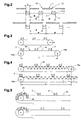
- FIG. 2 schematically shows various settings of a pitch D between successive sliding cam 9 and thus also between successive trailing edge product 22.
- the pitch D can be adapted to different product length respectively compartment length A, B.
- This product distance C can be predetermined by the subsequent machining process. In particular, it may be desirable that the product distance C does not depend on the product length A, B. Otherwise, short products would lead to longer product intervals.
- FIG. 3 shows a schematic diagram of an embodiment of the invention with a length-adjustable and thereby elastic tension element 14 in two positions.
- the tension element is preferably an elastic rope or band 14, for example made of rubber or plastic. It bypasses at least two deflection rollers 19a, which form the transition from the conveying path 18 on the working strand to the return strand and determine a length L of the conveying path 18. Between the pulleys 19 a, the rope or belt 14 extends substantially linearly, whereby it can also be supported by (not shown) support rollers or support rails. At least one of the deflection rollers 19a is displaceable along this linear direction, so that the distance between the deflection rollers 19a can be adjusted.
- the tray length A, B is adjustable in a simple manner.
- that deflection roller 19a which is located on the side for transferring the products 2 to the processing device 4, fixedly arranged, and the opposite guide roller 19a with its axis in the longitudinal direction of the conveying path 18 is movable.
- FIG. 4 shows a schematic diagram of an embodiment of the invention with a length-adjustable conveyor element 15 in two positions.
- the conveying element 15 conveys the alignment elements 5 and is designed as a buffer chain construction, ie with an adjustable distance between the chain links.
- the change in length of the tension element and the distribution of the change in length to the compartment length A, B is preferably effected by means of a slide control (not shown).
- FIG. 5 shows a schematic diagram of an embodiment of the invention with freely definable cam intervals, in operation with a first and a second product spacing:
- the alignment 5 are optional by a clamping mechanism or locking mechanism to a conveyor, in particular a flexible but not substantially elastic conveyor such as a pull rope Coupling is controlled by means of a release device 24.
- a release device 24 In front of the release device 24, returning alignment elements 5 are retained in a storage position 23 and released in a controlled manner, so that the desired compartment length A, B is created. Detecting the length of the compartment and releasing the alignment elements 5 can be effected by mechanical, electrical, pneumatic or by a combination of such elements.
- FIG. 6 schematically shows a variant of the embodiments of Figures 3 or 4 in two positions.
- the two pulleys 19 a are stationary and the length adjustment is achieved by adjusting at least one other roller or tension roller 19 b, via which the return strand 20 leads.
- the axis of the tension roller 19b is displaced perpendicular to the connecting line between the guide rollers 19a.
- An analogous effect can also be achieved with more than one tensioning roller 19b.
- This tension principle can also be applied to the embodiment of FIG. 4 be applied.
- FIG. 7 shows different cam shapes.
- a leading cam 6 is chamfered on the rear side or trailing surface 7, respectively provided with an inclined surface 8.
- a sliding cam 9 has at the front or leading surface 10 a forwardly inclined in the conveying direction alignment surface 11. By the front inclined surface 11, the products 2 are better held together with their trailing edges 22 products.
- the leading and trailing surfaces are perpendicular to the conveying direction.
- the sliding cam 9 is larger than the leading cam 6 is formed to accommodate greater forces.
- FIG. 8 schematically shows a plan view of a conveyor device 1 with parallel pulling members 14 and attached thereto alignment elements 5, and optional support means 13 for receiving and supporting the products.
- tension members and support means straightening or straightening straps 26 are arranged for the lateral alignment of the products 2.
Landscapes
- Engineering & Computer Science (AREA)
- Mechanical Engineering (AREA)
- Attitude Control For Articles On Conveyors (AREA)
- Discharge By Other Means (AREA)
Applications Claiming Priority (1)
| Application Number | Priority Date | Filing Date | Title |
|---|---|---|---|
| CH01537/08A CH699597A1 (de) | 2008-09-29 | 2008-09-29 | Fördervorrichtung zum Fördern und Ausrichten von flachen und optional flexiblen Produkten oder von Stapeln von flachen Produkten. |
Publications (2)
| Publication Number | Publication Date |
|---|---|
| EP2210841A2 true EP2210841A2 (fr) | 2010-07-28 |
| EP2210841A3 EP2210841A3 (fr) | 2010-12-29 |
Family
ID=40340470
Family Applications (1)
| Application Number | Title | Priority Date | Filing Date |
|---|---|---|---|
| EP09405167A Withdrawn EP2210841A3 (fr) | 2008-09-29 | 2009-09-25 | Convoyeur avec des cames d'alignement |
Country Status (5)
| Country | Link |
|---|---|
| US (1) | US8061505B2 (fr) |
| EP (1) | EP2210841A3 (fr) |
| AU (1) | AU2009222520A1 (fr) |
| CA (1) | CA2680631A1 (fr) |
| CH (1) | CH699597A1 (fr) |
Cited By (1)
| Publication number | Priority date | Publication date | Assignee | Title |
|---|---|---|---|---|
| DE102010022126A1 (de) * | 2010-05-20 | 2011-11-24 | Krones Ag | Automatische Einstellung der Teilung einer Förderkette |
Families Citing this family (4)
| Publication number | Priority date | Publication date | Assignee | Title |
|---|---|---|---|---|
| CH703561A1 (de) | 2010-08-06 | 2012-02-15 | Ferag Ag | Vorrichtung zur Ausrichtung eines flächigen Produktes. |
| US8596629B2 (en) * | 2011-11-03 | 2013-12-03 | Pitney Bowes Inc. | Adaptive registration/binding apparatus for preparing collations |
| CN107826720B (zh) * | 2017-11-28 | 2024-04-26 | 苏州索力旺新能源科技有限公司 | 一种光伏接线盒用导电片的传送装置 |
| WO2022269728A1 (fr) * | 2021-06-22 | 2022-12-29 | 株式会社ハイテム | Structure d'auge d'alimentation et aide à l'alimentation |
Citations (9)
| Publication number | Priority date | Publication date | Assignee | Title |
|---|---|---|---|---|
| US4502592A (en) | 1982-02-13 | 1985-03-05 | E.C.H. Will (Gmbh & Co.) | Apparatus for intermittently transporting stacks of paper sheets or the like |
| DE3335583A1 (de) | 1983-09-30 | 1985-04-18 | Maschinenbau Oppenweiler Gmbh, 7155 Oppenweiler | Vorschubvorrichtung zum absatzweisen verschieben von bogenstapeln, insbesondere von gefalzten heften |
| EP0276409A2 (fr) | 1987-01-26 | 1988-08-03 | Ferag AG | Convoyeur pour l'alimentation intermittente |
| EP0300170A1 (fr) | 1987-07-21 | 1989-01-25 | Ferag AG | Procédé et dispositif de séparation de produits se chevauchant, en particulier de produits imprimés |
| EP0309702A1 (fr) | 1987-10-02 | 1989-04-05 | Ferag AG | Bande sans fin pour le transport d'articles |
| US5072573A (en) | 1990-01-12 | 1991-12-17 | Tisma Machine Corporation | Apparatus with adjustable width trays for automatic packaging machines |
| US6293544B1 (en) | 1999-12-22 | 2001-09-25 | Xerox Corporation | Apparatus and method for registering and conveying a compiled set of sheets |
| US20030136086A1 (en) | 2001-12-05 | 2003-07-24 | Kalany Robert M. | Packaging apparatus and methods |
| EP1410992A1 (fr) | 2002-10-14 | 2004-04-21 | SITMA S.p.A. | Dispositif d'alignement et procédé pour alimenter des produits dans une machine automatique d'emballage |
Family Cites Families (14)
| Publication number | Priority date | Publication date | Assignee | Title |
|---|---|---|---|---|
| US3057456A (en) * | 1959-08-04 | 1962-10-09 | Sig Schweiz Industrieges | Endless type conveyer |
| DE1150021B (de) * | 1959-08-04 | 1963-06-06 | Sig Schweiz Industrieges | Foerdervorrichtung mit in verstellbaren Abstaenden sich folgenden Mitnahmeorganen |
| US3040634A (en) * | 1960-04-27 | 1962-06-26 | Fmc Corp | Carton set-up mechanism |
| FR1465356A (fr) * | 1961-11-07 | 1967-01-13 | Remy & Cie E P | Dispositif pour le groupage en nombre déterminé d'objets divers |
| US3368660A (en) * | 1966-11-25 | 1968-02-13 | Johns Nigrelli Johns | Article grouper and feeder |
| US3872647A (en) * | 1973-03-22 | 1975-03-25 | Marinus J M Langen | Carton loader |
| US3896711A (en) * | 1974-03-13 | 1975-07-29 | Container Corp | Apparatus for erecting carton tubes |
| CA1009175A (en) * | 1974-04-19 | 1977-04-26 | Arthur G. Alsop | Stacking mechanism and method |
| US4552261A (en) * | 1983-12-27 | 1985-11-12 | Standard-Knapp, Inc. | Article grouper for case packer |
| US5081821A (en) * | 1988-11-16 | 1992-01-21 | Pemco Company | Method and apparatus for manipulating stacks of paper sheets in wrapping machines |
| GB9421177D0 (en) * | 1994-10-20 | 1994-12-07 | Riverwood Int Ltd | Spacing conveyor mechanism |
| US5806659A (en) * | 1996-10-18 | 1998-09-15 | Bell And Howell Mail Processing Systems | Chain apparatus for high-speed media processing |
| DE102005026639B4 (de) * | 2005-06-09 | 2009-01-08 | Khs Ag | Vorrichtung zum Aufteilen, Eintakten und Gruppieren von Stückgütern |
| GB2436550A (en) * | 2006-03-31 | 2007-10-03 | Meadwestvaco Packaging Systems | Releasably engaging lugs and means of positioning the lugs |
-
2008
- 2008-09-29 CH CH01537/08A patent/CH699597A1/de not_active Application Discontinuation
-
2009
- 2009-09-24 CA CA2680631A patent/CA2680631A1/fr not_active Abandoned
- 2009-09-25 EP EP09405167A patent/EP2210841A3/fr not_active Withdrawn
- 2009-09-28 US US12/568,405 patent/US8061505B2/en not_active Expired - Fee Related
- 2009-09-29 AU AU2009222520A patent/AU2009222520A1/en not_active Abandoned
Patent Citations (9)
| Publication number | Priority date | Publication date | Assignee | Title |
|---|---|---|---|---|
| US4502592A (en) | 1982-02-13 | 1985-03-05 | E.C.H. Will (Gmbh & Co.) | Apparatus for intermittently transporting stacks of paper sheets or the like |
| DE3335583A1 (de) | 1983-09-30 | 1985-04-18 | Maschinenbau Oppenweiler Gmbh, 7155 Oppenweiler | Vorschubvorrichtung zum absatzweisen verschieben von bogenstapeln, insbesondere von gefalzten heften |
| EP0276409A2 (fr) | 1987-01-26 | 1988-08-03 | Ferag AG | Convoyeur pour l'alimentation intermittente |
| EP0300170A1 (fr) | 1987-07-21 | 1989-01-25 | Ferag AG | Procédé et dispositif de séparation de produits se chevauchant, en particulier de produits imprimés |
| EP0309702A1 (fr) | 1987-10-02 | 1989-04-05 | Ferag AG | Bande sans fin pour le transport d'articles |
| US5072573A (en) | 1990-01-12 | 1991-12-17 | Tisma Machine Corporation | Apparatus with adjustable width trays for automatic packaging machines |
| US6293544B1 (en) | 1999-12-22 | 2001-09-25 | Xerox Corporation | Apparatus and method for registering and conveying a compiled set of sheets |
| US20030136086A1 (en) | 2001-12-05 | 2003-07-24 | Kalany Robert M. | Packaging apparatus and methods |
| EP1410992A1 (fr) | 2002-10-14 | 2004-04-21 | SITMA S.p.A. | Dispositif d'alignement et procédé pour alimenter des produits dans une machine automatique d'emballage |
Cited By (3)
| Publication number | Priority date | Publication date | Assignee | Title |
|---|---|---|---|---|
| DE102010022126A1 (de) * | 2010-05-20 | 2011-11-24 | Krones Ag | Automatische Einstellung der Teilung einer Förderkette |
| DE102010022126A9 (de) * | 2010-05-20 | 2017-04-27 | Krones Aktiengesellschaft | Automatische Einstellung der Teilung einer Förderkette |
| DE102010022126B4 (de) * | 2010-05-20 | 2021-03-25 | Krones Aktiengesellschaft | Automatische Einstellung der Teilung einer Förderkette |
Also Published As
| Publication number | Publication date |
|---|---|
| AU2009222520A1 (en) | 2010-04-15 |
| CA2680631A1 (fr) | 2010-03-29 |
| EP2210841A3 (fr) | 2010-12-29 |
| US8061505B2 (en) | 2011-11-22 |
| CH699597A1 (de) | 2010-03-31 |
| US20100078292A1 (en) | 2010-04-01 |
Similar Documents
| Publication | Publication Date | Title |
|---|---|---|
| EP0550828B1 (fr) | Procédé et dispositif de traitement de produits imprimés | |
| EP1119507B1 (fr) | Dispositif permettant de recevoir et de transporter des objets | |
| EP1118564B1 (fr) | Dispositif de transport | |
| DE69103185T2 (de) | Verfahren und Vorrichtung zum Bilden von Stapeln von der Oberseite eines Stapels von Blättern in einer Maschine zur Herstellung von Verpackungen. | |
| DE2938010C2 (de) | Vorrichtung zum Ausrichten von in einer ununterbrochen, geschlossenen Reihe zugeführten Gegenständen | |
| EP0510525B1 (fr) | Procédé et dispositif pour traiter des produits imprimés | |
| EP2428471B1 (fr) | Convoyeur | |
| EP1169249B1 (fr) | Procede et dispositif pour transporter des produits en vrac | |
| EP1320501A1 (fr) | Procede et dispositif pour transferer un produit dans une machine d'emballage | |
| EP2210841A2 (fr) | Convoyeur avec des cames d'alignement | |
| DE1813817C3 (de) | Vorrichtung zum Trennen und Weiterfördern von in einer ununterbrochenen Reihe zulaufenden flachen Gegenständen | |
| DE69715080T2 (de) | Verfahren und Einheit zum Bilden und Fördern von Gruppen von Gegenständen | |
| EP0944544B1 (fr) | Procede et dispositif pour transporter des produits maintenus individuellement | |
| CH680851A5 (fr) | ||
| DE60221268T2 (de) | Übergabevorrichtung für zylindrische stapel von auf einer kante angeordneten produkten | |
| WO2017198772A2 (fr) | Dispositif et procédé pour la réunion, la distribution et/ou la redistribution définies d'une marchandise de détail et/ou de groupes de marchandises de détail | |
| EP0478911A1 (fr) | Dispositif de transfert sélectif d'articles se chevauchant d'un premier chemin de transport à un deuxième chemin de transport | |
| DE102017004232A1 (de) | Objekttransportvorrichtung | |
| EP1231176B1 (fr) | Dispositif pour alimenter des produits imprimés dans un canal de transport | |
| EP3693299B1 (fr) | Dispositif de transport continu des marchandises transportées et procédé de transport continu des marchandises | |
| DE1561141B2 (de) | Vorrichtung zum einfuehren von beilagen in gefaltete druckerzeugnisse | |
| EP2228332B1 (fr) | Dispositif et méthode pour reprendre des produits plats flexibles | |
| EP0499691A1 (fr) | Procédé pour traiter des produits imprimés alimentés de façon continue en une formation imbriquée ainsi que dispositif pour la mise en oeuvre dudit procédé | |
| EP0458733B1 (fr) | Méthode et dispositif pour transporter des produits imprimés | |
| EP1274639B1 (fr) | Dispositif permettant d'acheminer des objets plats |
Legal Events
| Date | Code | Title | Description |
|---|---|---|---|
| PUAI | Public reference made under article 153(3) epc to a published international application that has entered the european phase |
Free format text: ORIGINAL CODE: 0009012 |
|
| AK | Designated contracting states |
Kind code of ref document: A2 Designated state(s): AT BE BG CH CY CZ DE DK EE ES FI FR GB GR HR HU IE IS IT LI LT LU LV MC MK MT NL NO PL PT RO SE SI SK SM TR |
|
| AX | Request for extension of the european patent |
Extension state: AL BA RS |
|
| PUAL | Search report despatched |
Free format text: ORIGINAL CODE: 0009013 |
|
| AK | Designated contracting states |
Kind code of ref document: A3 Designated state(s): AT BE BG CH CY CZ DE DK EE ES FI FR GB GR HR HU IE IS IT LI LT LU LV MC MK MT NL NO PL PT RO SE SI SK SM TR |
|
| AX | Request for extension of the european patent |
Extension state: AL BA RS |
|
| 17P | Request for examination filed |
Effective date: 20110331 |
|
| STAA | Information on the status of an ep patent application or granted ep patent |
Free format text: STATUS: THE APPLICATION IS DEEMED TO BE WITHDRAWN |
|
| 18D | Application deemed to be withdrawn |
Effective date: 20130403 |