EP2211018B1 - Turbinenschaufel - Google Patents
Turbinenschaufel Download PDFInfo
- Publication number
- EP2211018B1 EP2211018B1 EP09252482A EP09252482A EP2211018B1 EP 2211018 B1 EP2211018 B1 EP 2211018B1 EP 09252482 A EP09252482 A EP 09252482A EP 09252482 A EP09252482 A EP 09252482A EP 2211018 B1 EP2211018 B1 EP 2211018B1
- Authority
- EP
- European Patent Office
- Prior art keywords
- airfoil
- shell
- shell portion
- edge
- hollow
- Prior art date
- Legal status (The legal status is an assumption and is not a legal conclusion. Google has not performed a legal analysis and makes no representation as to the accuracy of the status listed.)
- Not-in-force
Links
- 238000007596 consolidation process Methods 0.000 claims abstract description 21
- 239000012530 fluid Substances 0.000 claims description 14
- 229920001169 thermoplastic Polymers 0.000 claims description 10
- 239000004416 thermosoftening plastic Substances 0.000 claims description 10
- 230000000712 assembly Effects 0.000 claims description 8
- 238000000429 assembly Methods 0.000 claims description 8
- 239000002131 composite material Substances 0.000 claims description 8
- 239000012815 thermoplastic material Substances 0.000 claims description 8
- 238000000034 method Methods 0.000 claims description 7
- 238000010438 heat treatment Methods 0.000 claims description 2
- 238000003825 pressing Methods 0.000 claims description 2
- 239000004696 Poly ether ether ketone Substances 0.000 description 5
- 229920002530 polyetherether ketone Polymers 0.000 description 5
- OKTJSMMVPCPJKN-UHFFFAOYSA-N Carbon Chemical compound [C] OKTJSMMVPCPJKN-UHFFFAOYSA-N 0.000 description 4
- 239000000463 material Substances 0.000 description 4
- 239000004743 Polypropylene Substances 0.000 description 3
- 229910052799 carbon Inorganic materials 0.000 description 3
- 239000003822 epoxy resin Substances 0.000 description 3
- 229920001652 poly(etherketoneketone) Polymers 0.000 description 3
- 229920000647 polyepoxide Polymers 0.000 description 3
- 229920001155 polypropylene Polymers 0.000 description 3
- 239000004676 acrylonitrile butadiene styrene Substances 0.000 description 2
- 239000003365 glass fiber Substances 0.000 description 2
- 238000007731 hot pressing Methods 0.000 description 2
- 238000001746 injection moulding Methods 0.000 description 2
- 239000004593 Epoxy Substances 0.000 description 1
- XECAHXYUAAWDEL-UHFFFAOYSA-N acrylonitrile butadiene styrene Chemical compound C=CC=C.C=CC#N.C=CC1=CC=CC=C1 XECAHXYUAAWDEL-UHFFFAOYSA-N 0.000 description 1
- 229920000122 acrylonitrile butadiene styrene Polymers 0.000 description 1
- 239000000853 adhesive Substances 0.000 description 1
- 230000001070 adhesive effect Effects 0.000 description 1
- 238000004891 communication Methods 0.000 description 1
- 230000003628 erosive effect Effects 0.000 description 1
- 239000000446 fuel Substances 0.000 description 1
- 239000011521 glass Substances 0.000 description 1
- 229910002804 graphite Inorganic materials 0.000 description 1
- 239000010439 graphite Substances 0.000 description 1
- 238000005470 impregnation Methods 0.000 description 1
- 238000002347 injection Methods 0.000 description 1
- 239000007924 injection Substances 0.000 description 1
- 238000005304 joining Methods 0.000 description 1
- 238000004519 manufacturing process Methods 0.000 description 1
- 239000007769 metal material Substances 0.000 description 1
- 238000012986 modification Methods 0.000 description 1
- 230000004048 modification Effects 0.000 description 1
- 239000004033 plastic Substances 0.000 description 1
- 229920003023 plastic Polymers 0.000 description 1
- -1 polypropylene Polymers 0.000 description 1
- 230000002787 reinforcement Effects 0.000 description 1
- 238000007789 sealing Methods 0.000 description 1
- 239000000126 substance Substances 0.000 description 1
- 238000003466 welding Methods 0.000 description 1
Images


Classifications
-
- F—MECHANICAL ENGINEERING; LIGHTING; HEATING; WEAPONS; BLASTING
- F01—MACHINES OR ENGINES IN GENERAL; ENGINE PLANTS IN GENERAL; STEAM ENGINES
- F01D—NON-POSITIVE DISPLACEMENT MACHINES OR ENGINES, e.g. STEAM TURBINES
- F01D5/00—Blades; Blade-carrying members; Heating, heat-insulating, cooling or antivibration means on the blades or the members
- F01D5/12—Blades
- F01D5/14—Form or construction
- F01D5/147—Construction, i.e. structural features, e.g. of weight-saving hollow blades
-
- F—MECHANICAL ENGINEERING; LIGHTING; HEATING; WEAPONS; BLASTING
- F01—MACHINES OR ENGINES IN GENERAL; ENGINE PLANTS IN GENERAL; STEAM ENGINES
- F01D—NON-POSITIVE DISPLACEMENT MACHINES OR ENGINES, e.g. STEAM TURBINES
- F01D9/00—Stators
- F01D9/02—Nozzles; Nozzle boxes; Stator blades; Guide conduits, e.g. individual nozzles
- F01D9/04—Nozzles; Nozzle boxes; Stator blades; Guide conduits, e.g. individual nozzles forming ring or sector
- F01D9/041—Nozzles; Nozzle boxes; Stator blades; Guide conduits, e.g. individual nozzles forming ring or sector using blades
-
- Y—GENERAL TAGGING OF NEW TECHNOLOGICAL DEVELOPMENTS; GENERAL TAGGING OF CROSS-SECTIONAL TECHNOLOGIES SPANNING OVER SEVERAL SECTIONS OF THE IPC; TECHNICAL SUBJECTS COVERED BY FORMER USPC CROSS-REFERENCE ART COLLECTIONS [XRACs] AND DIGESTS
- Y10—TECHNICAL SUBJECTS COVERED BY FORMER USPC
- Y10T—TECHNICAL SUBJECTS COVERED BY FORMER US CLASSIFICATION
- Y10T29/00—Metal working
- Y10T29/49—Method of mechanical manufacture
- Y10T29/49316—Impeller making
- Y10T29/4932—Turbomachine making
- Y10T29/49321—Assembling individual fluid flow interacting members, e.g., blades, vanes, buckets, on rotary support member
-
- Y—GENERAL TAGGING OF NEW TECHNOLOGICAL DEVELOPMENTS; GENERAL TAGGING OF CROSS-SECTIONAL TECHNOLOGIES SPANNING OVER SEVERAL SECTIONS OF THE IPC; TECHNICAL SUBJECTS COVERED BY FORMER USPC CROSS-REFERENCE ART COLLECTIONS [XRACs] AND DIGESTS
- Y10—TECHNICAL SUBJECTS COVERED BY FORMER USPC
- Y10T—TECHNICAL SUBJECTS COVERED BY FORMER US CLASSIFICATION
- Y10T29/00—Metal working
- Y10T29/49—Method of mechanical manufacture
- Y10T29/49316—Impeller making
- Y10T29/4932—Turbomachine making
- Y10T29/49323—Assembling fluid flow directing devices, e.g., stators, diaphragms, nozzles
Definitions
- the present invention relates to airfolls, and particularly hollow airfoils.
- Hollow airfoils e.g. fans, blades or vanes
- gas turbine engines are known.
- hollow metallic fan blades have been in operation for many years and also hollow metallic guide vanes.
- GB2147055A discloses such a hollow metallic airfoil.
- GB2154286A discloses a hollow composite airfoil in which a process for forming the airfoil using carbon, graphite or glass reinforced epoxy resin composites is proposed.
- the airfoil has an outer shell producing the airfoil surfaces and a corrugated internal support.
- the shell is formed from stacked assemblies of laminae, one stack for each side of the airfoil and are joined to each other at the leading and trailing edge of the airfoil.
- a boot at one end of the airfoil and a mounting platform at the other end of the airfoil seal off the interior of the airfoil from the exterior.
- a first aspect of the present invention provides an airfoil having:
- the edge shell portions When the hollow shell has a leading edge shell portion and a trailing edge shell portion, the edge shell portions may be joined together along a suction side of the airfoil and along a pressure side of the airfoil during consolidation of the pre-forms.
- the edge shell portions can completely envelope the airfoil, and the number of joins between different portions of the hollow shell can be reduced.
- the or each edge shell portion is formed of fibre-reinforced thermoplastic composite material, such as chopped strand reinforced injection moulded thermoplastic.
- the thermoplastic material can comprise or consist of polyether-ether ketone (PEEK), polyetherketoneketone (PEKK), acrylonitrile butadiene styrene (ABS), or polypropylene (PP).
- the fibres can be, for example, carbon or glass fibres.
- the or each edge shell portion may form part of an outer layer of the hollow shell.
- the hollow shell can have an inner layer and an outer layer.
- the inner layer can be optimised for load bearing capabilities.
- the outer layer can be optimised to protect the airfoil against external threats, such as foreign object or erosion damage.
- the outer surface of the hollow shell can also be adapted or treated to provide low adhesion to dirt and ice, chemical protection, and/or protection against lightning strike damage.
- the outer surface can be metallised.
- the inner layer of the hollow shell may be formed from laminated fibre-reinforced pre-impregnated portions.
- the fibres may be carbon or glass fibres.
- the impregnation material may be a plastic material. Preferably it is a thermoplastic material such as PEEK.
- the inner layer is formed from a suction side shell portion and a pressure side shell portion, these two portions being joined during consolidation at the leading and trailing edges.
- the join at the leading edge can be protected by a leading edge shell portion of the outer layer
- the join at the trailing edge can be protected by a trailing edge shell portion of the outer layer.
- the suction and pressure side shell portions can be two stacked assemblies of pre-impregnated fibre-reinforced laminae, the assemblies being joined during consolidation at the leading and trailing edges.
- Such assemblies may be consolidated into respective unitary bodies before consolidation of the airfoil, or alternatively may only be consolidated themselves during consolidation of the airfoil.
- surfaces of the core and inner surfaces of the hollow shell are formed of thermoplastic material, the core surfaces and the hollow shell inner surfaces being joined together during consolidation of the pre-forms.
- the core may be formed of fibre-reinforced thermoplastic composite material.
- the core is a laminated fibre-reinforced part pre-impregnated with thermoplastic.
- the core may be formed of thermoplastic coated metallic material.
- the airfoil is an airfoil component of a gas turbine engine, such as a guide vane.
- Surfaces of the core and inner surfaces of the hollow shell may define passages which extend along the airfoil.
- one or more of the passages are configured to act as fluid or wiring conduits.
- the surfaces of the core and the inner surfaces of the hollow shell are formed of thermoplastic material.
- thermoplastic material can be PEEK.
- the airfoil may further have end caps at the ends of the airfoil, the end caps having openings which provide access to the passages. In this way, fluid and/or wiring can enter and exit through the passages.
- the airfoil may further have fluid flow pipes and/or wiring passing through one or more of the passages.
- the airfoil is an airfoil component of a gas turbine engine, such as a guide vane.
- a second aspect of the invention provides the use of the airfoil of the previous aspect for the transport of fluid and/or wiring, wherein the fluid and/or wiring is conveyed through one or more passages of the airfoil.
- a third aspect of the invention provides a method of producing the airfoil of the first aspect, including the steps of:
- the positioning step typically includes positioning removable mandrels around the corrugated core pre-form to support the corrugated core pre-form during the consolidation step.
- the hollow shell pre-form may have an outer layer and an inner layer, the outer layer having the or each edge shell portion.
- the inner layer is formed from a suction side shell portion and a pressure side shell portion which are joined during consolidation at the leading and trailing edges of the airfoil.
- the suction and pressure side shell portions may be respective stacked assemblies of pre-impregnated fibre-reinforced laminae.
- Figure 1 shows schematically a perspective view of an embodiment of an airfoil according to the present invention.
- the airfoil has a corrugated core 1, and a hollow shell formed from an inner layer 2, and an outer layer enveloping the inner layer 3.
- the core has lands 4 which contact inner surfaces of the inner layer to support the hollow shell.
- the inner surfaces of the inner layer and surfaces of the core define passages 5 which extend from one end of the airfoil to the other.
- End caps 6 (only the far cap being shown in Figure 1 ) close the ends of the airfoil.
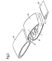
- Figure 2 is an exploded view of parts of the airfoil of Figure 1 (excluding the cap).
- a pre-form for the corrugated core 1 is produced by hot-pressing a flat fibre-reinforced laminated sheet of thermoplastic into the desired corrugated shape.
- the inner layer 2 has suction side 2a and pressure side 2b shell portions, and the outer layer 3 has leading edge 3a and trailing edge 3b shell portions.
- the inner suction side and pressure side shell portions are formed into the desired shapes by hot-pressing fibre-reinforced laminated sheets of thermoplastic, and the edge shell portions are formed by injection moulding chopped strand reinforced thermoplastic to produce unitary bodies which wrap around their respective edges.
- the pre-form for the core 1 and a pre-form for the hollow shell, assembled from the shell portions 2a, 2b, 3a, 3b, are brought together.
- the pre-forms are then consolidated by the application of heat and pressure.
- the core 1 bonds to the inner surfaces of the side shell portions 2a, 2b; the side shell portions 2a, 2b themselves bond together along the leading and trailing edges of the airfoil; and the edge shell portions 3a, 3b bond to and envelope the outer surfaces of the side shell portions 2a, 2b. In this way, the joints between the side shell portions 2a, 2b are protected by the edge shell 3a, 3b portions.
- edge shell 3a, 3b portions have corresponding bevelled joining edges 10 at which they bond together along the suction and pressure sides of the airfoil.
- mandrels 7 are inserted in the passages 5 during consolidation. The mandrels are removed after the consolidation is complete.
- Figure 3 is an exploded view of the consolidated airfoil and its end caps 6.
- the caps are added to each end of the airfoil and formed with openings 9 that allow communication with at least some of the passages 5.
- the caps are also formed from thermoplastic, but use chopped strand reinforcement to facilitate injection moulding of their relatively complex shapes.
- the caps can be joined to the ends of the airfoil by e.g. localised welding or adhesive.
- the airfoil is relatively easy to manufacture. It is also easier to recycle than e.g. fibre-reinforced epoxy based systems.
- the airfoil can perform the same tasks as hollow metallic guide vanes, but can additionally convey fluids and/or wiring through the passages, either directly through the passages or via service pipes inserted through the passages.
- the airfoil can also be lighter than a hollow metallic equivalent.
- the passages can form fluid conduits which are chemically resistant and have good temperature capabilities.
Landscapes
- Engineering & Computer Science (AREA)
- Mechanical Engineering (AREA)
- General Engineering & Computer Science (AREA)
- Architecture (AREA)
- Turbine Rotor Nozzle Sealing (AREA)
- Saccharide Compounds (AREA)
Claims (15)
- Turbinenschaufel, bestehend aus:einem hohlen Hülsenkörper (2a, 2b, 3a, 3b), der die äußeren Oberflächen der Turbinenschaufel bildet undeinem gewellten Kern (1) innerhalb des Hülsenkörpers, der die inneren Oberflächen des Hülsenkörpers berührt, um den Hülsenkörper abzustützen;wobei die Turbinenschaufel durch Verbindung einer hohlen Hülsenkörpervorform und einer gewellten Kernvorform (1) hergestellt ist, dadurch gekennzeichnet,dass wenigstens ein Teil des hohlen Hülsenkörpers einen Hülsenvorderkantenabschnitt (3a) und/oder einen Hülsenhinterkantenabschnitt (3b) aufweist, die vor Vereinigung der Vorformen einen einheitlichen Formkörper bilden, der die jeweilige Kante umschließt.
- Turbinenschaufel nach Anspruch 1, bei welcher der hohle Hülsenkörper einen Hülsenvorderkantenabschnitt (3a) und einen Hülsenhinterkantenabschnitt (3b) aufweist und die Hülsenkantenabschnitte längs einer Saugseite der Turbinenschaufel und längs einer Druckseite der Turbinenschaufel miteinander verbunden werden, während die Vereinigung der Vorformen erfolgt.
- Turbinenschaufel nach Anspruch 1 oder Anspruch 2, bei welcher der oder jeder Hülsenkantenabschnitt (3a, 3b) aus faserverstärktem, thermoplastischen Verbundmaterial hergestellt ist.
- Turbinenschaufel nach einem der vorherigen Ansprüche, bei welcher die Oberflächen des Kerns (1) und die inneren Oberflächen des hohlen Hülsenkörpers (2a, 2b, 3a, 3b) aus thermoplastischem Material hergestellt sind, wobei die Kernoberflächen und die inneren Oberflächen des hohlen Hülsenkörpers miteinander verbunden werden, während die Vorformen vereinigt werden.
- Turbinenschaufel nach einem der vorherigen Ansprüche, bei welcher der hohle Hülsenkörper eine innere Schicht (2a, 2b) und eine äußere Schicht (3a, 3b) aufweist und die äußere Schicht den oder jeden Hülsenkantenabschnitt bildet.
- Turbinenschaufel nach Anspruch 5, bei welcher die innere Schicht (2a, 2b) von einem Saugseitenhülsenabschnitt und einem Druckseitenhülsenabschnitt gebildet ist, die während der Vereinigung an der Vorderkante und an der Hinterkante der Turbinenschaufel festgelegt werden.
- Turbinenschaufel nach Anspruch 6, bei welcher die Saugseitenhülsenabschnitte und die Druckseitenhülsenabschnitte jeweils gestapelte Aufbauten aus vorimprägnierten, faserverstärkten Schichten sind.
- Turbinenschaufel nach einem der vorherigen Ansprüche, bei welcher die Oberflächen des Kerns und die inneren Oberflächen des hohlen Hülsenkörpers Kanäle (5) bilden, die sich längs der Turbinenschaufel erstrecken.
- Turbinenschaufel nach Anspruch 8, welche Endkappen (9) an den Enden aufweist, die Öffnungen besitzen, die einen Zugang zu den Kanälen bilden.
- Turbinenschaufel nach den Ansprüchen 8 oder 9, bei welcher einer oder mehrere der Kanäle als Fluidleitung oder als Kabelführung ausgebildet sind.
- Verwendung der Turbinenschaufel nach einem der Ansprüche 8 bis 10 zum Transport eines Fluids oder/und zur Kabelführung, wobei das Fluid oder/und das Kabel durch einen oder mehrere Kanäle geführt sind.
- Verfahren zur Herstellung einer Turbinenschaufel nach einem der Ansprüche 1 bis 10, mit den folgenden Schritten:es werden eine hohle Hülsenvorform (2a, 2b, 3a, 3b) und eine gewellte Kernvorform (1) erzeugt, die einen einheitlichen Vorderkantenhülsenabschnitt (3a) und/oder einen einheitlichen Hinterkantenhülsenabschnitt (3b) aufweisen, wobei der oder jeder Hülsenkantenabschnitt eine Form aufweist, die die jeweilige Kante umhüllt;es wird die gewellte Kernvorform in die hohle Hülsenvorform eingefügt und es wird die hohle Hülsenvorform mit der gewellten Kernvorform vereinigt, um so die Turbinenschaufel zu erzeugen.
- Verfahren nach Anspruch 12, bei welchem die hohle Hülsenvorform eine äußere Schicht (3a, 3b) und eine innere Schicht (2a, 2b) aufweist, die jeweils den oder jeden Hülsenkantenabschnitt haben.
- Verfahren nach Anspruch 13, bei welchem die innere Schicht (2a, 2b) aus einem Saugseitenabschnitt und einem Druckseitenabschnitt geformt ist, welche Abschnitte während der Vereinigung an den Vorder- und Hinterkanten der Turbinenschaufel miteinander verbunden werden, wobei der Saugseitenhülsenabschnitt und der Druckseitenhülsenabschnitt jeweils als gestapelter Aufbau vorimprägnierter, faserverstärkter Schichten ausgebildet ist.
- Verfahren nach Anspruch 14, bei welchem der Vereinigungsschritt ein Pressen und Erhitzen der hohlen Hülsenvorform und der gewellten Kernvorform umfasst, um die Vorformen zu bilden.
Applications Claiming Priority (1)
| Application Number | Priority Date | Filing Date | Title |
|---|---|---|---|
| GBGB0822909.8A GB0822909D0 (en) | 2008-12-17 | 2008-12-17 | Airfoil |
Publications (2)
| Publication Number | Publication Date |
|---|---|
| EP2211018A1 EP2211018A1 (de) | 2010-07-28 |
| EP2211018B1 true EP2211018B1 (de) | 2011-08-31 |
Family
ID=40326190
Family Applications (1)
| Application Number | Title | Priority Date | Filing Date |
|---|---|---|---|
| EP09252482A Not-in-force EP2211018B1 (de) | 2008-12-17 | 2009-10-27 | Turbinenschaufel |
Country Status (4)
| Country | Link |
|---|---|
| US (1) | US8573948B2 (de) |
| EP (1) | EP2211018B1 (de) |
| AT (1) | ATE522701T1 (de) |
| GB (1) | GB0822909D0 (de) |
Families Citing this family (27)
| Publication number | Priority date | Publication date | Assignee | Title |
|---|---|---|---|---|
| US8888451B2 (en) * | 2007-10-11 | 2014-11-18 | Volvo Aero Corporation | Method for producing a vane, such a vane and a stator component comprising the vane |
| US8690531B2 (en) | 2010-12-30 | 2014-04-08 | General Electroc Co. | Vane with spar mounted composite airfoil |
| EP2472063B1 (de) | 2010-12-30 | 2015-02-11 | Techspace Aero S.A. | Leitschaufel aus Verbundmaterial |
| US8727721B2 (en) | 2010-12-30 | 2014-05-20 | General Electric Company | Vane with spar mounted composite airfoil |
| FR2978495B1 (fr) * | 2011-07-25 | 2013-08-02 | Snecma | Carter, notamment carter intermediaire, de turboreacteur |
| DE102013219774A1 (de) * | 2013-09-30 | 2015-04-02 | MTU Aero Engines AG | Schaufel für eine Gasturbine |
| EP2966264B1 (de) * | 2014-07-07 | 2021-09-22 | Safran Aero Boosters SA | Laufradschaufelsegment eines Verdichters eines axialen Turbotriebwerks |
| US9840184B2 (en) * | 2015-04-13 | 2017-12-12 | Charles Herbert Chadwell, IV | Strap retaining apparatus |
| BE1023290B1 (fr) * | 2015-07-22 | 2017-01-24 | Safran Aero Boosters S.A. | Aube composite de compresseur de turbomachine axiale |
| US10677259B2 (en) | 2016-05-06 | 2020-06-09 | General Electric Company | Apparatus and system for composite fan blade with fused metal lead edge |
| EP3428060A1 (de) * | 2017-07-13 | 2019-01-16 | Ratier-Figeac SAS | Hülle |
| RU2661433C1 (ru) * | 2017-10-30 | 2018-07-16 | Николай Борисович Болотин | Лопатка вентилятора газотурбинного двигателя |
| US11002139B2 (en) * | 2017-12-12 | 2021-05-11 | Hamilton Sundstrand Corporation | Cooled polymer component |
| US10746045B2 (en) | 2018-10-16 | 2020-08-18 | General Electric Company | Frangible gas turbine engine airfoil including a retaining member |
| US11111815B2 (en) | 2018-10-16 | 2021-09-07 | General Electric Company | Frangible gas turbine engine airfoil with fusion cavities |
| US11149558B2 (en) | 2018-10-16 | 2021-10-19 | General Electric Company | Frangible gas turbine engine airfoil with layup change |
| US11434781B2 (en) | 2018-10-16 | 2022-09-06 | General Electric Company | Frangible gas turbine engine airfoil including an internal cavity |
| US10837286B2 (en) | 2018-10-16 | 2020-11-17 | General Electric Company | Frangible gas turbine engine airfoil with chord reduction |
| US10760428B2 (en) | 2018-10-16 | 2020-09-01 | General Electric Company | Frangible gas turbine engine airfoil |
| FR3107299B1 (fr) * | 2020-02-14 | 2022-03-11 | Safran Aircraft Engines | Aube en matériau composite pour stator de turbomachine comprenant un noyau creux en plastique non poreux |
| US11230928B1 (en) * | 2020-07-22 | 2022-01-25 | Raytheon Technologies Corporation | Guide vane with truss structure and honeycomb |
| US12116903B2 (en) | 2021-06-30 | 2024-10-15 | General Electric Company | Composite airfoils with frangible tips |
| US11674399B2 (en) | 2021-07-07 | 2023-06-13 | General Electric Company | Airfoil arrangement for a gas turbine engine utilizing a shape memory alloy |
| US11668317B2 (en) | 2021-07-09 | 2023-06-06 | General Electric Company | Airfoil arrangement for a gas turbine engine utilizing a shape memory alloy |
| FR3127532B1 (fr) * | 2021-09-29 | 2023-10-13 | Safran Aircraft Engines | Module pour une turbomachine d’aeronef |
| US20230303264A1 (en) * | 2022-03-23 | 2023-09-28 | Rolls-Royce Corporation | Aircraft with ram air turbine disk with generator having blade tip integrated magnets |
| US11719119B1 (en) * | 2022-03-23 | 2023-08-08 | Rolls-Royce Corporation | Aircraft with ram air turbine disk with generator having blade shroud ring integrated magnets |
Family Cites Families (14)
| Publication number | Priority date | Publication date | Assignee | Title |
|---|---|---|---|---|
| US3095180A (en) | 1959-03-05 | 1963-06-25 | Stalker Corp | Blades for compressors, turbines and the like |
| US2981337A (en) * | 1959-09-08 | 1961-04-25 | Hiller Aircraft Corp | Propeller blade |
| IT1176673B (it) | 1983-09-23 | 1987-08-18 | Gen Electric | Pala cava per turbomacchina |
| GB2154286A (en) | 1984-02-13 | 1985-09-04 | Gen Electric | Hollow laminated airfoil |
| US4594761A (en) | 1984-02-13 | 1986-06-17 | General Electric Company | Method of fabricating hollow composite airfoils |
| US5056738A (en) | 1989-09-07 | 1991-10-15 | General Electric Company | Damper assembly for a strut in a jet propulsion engine |
| EP0495276A1 (de) | 1991-01-18 | 1992-07-22 | Ko-Jan Carlos Tsai | Verfahren zur Herstellung einer Verbundstruktur |
| GB9202982D0 (en) | 1992-02-13 | 1992-03-25 | Preci Spark Ltd | Reinforced vane |
| US5810552A (en) | 1992-02-18 | 1998-09-22 | Allison Engine Company, Inc. | Single-cast, high-temperature, thin wall structures having a high thermal conductivity member connecting the walls and methods of making the same |
| GB2365078B (en) * | 2000-07-27 | 2004-04-21 | Rolls Royce Plc | A gas turbine engine blade |
| US6454526B1 (en) * | 2000-09-28 | 2002-09-24 | Siemens Westinghouse Power Corporation | Cooled turbine vane with endcaps |
| JP2006507965A (ja) | 2002-04-29 | 2006-03-09 | ロールス − ロイス ネイブル マリーン、インコーポレイテッド | プロペラ |
| GB2402716B (en) | 2003-06-10 | 2006-08-16 | Rolls Royce Plc | A damped aerofoil structure |
| US8348604B2 (en) * | 2008-03-17 | 2013-01-08 | Rolls-Royce Corporation | Airfoil assembly and method of forming same |
-
2008
- 2008-12-17 GB GBGB0822909.8A patent/GB0822909D0/en not_active Ceased
-
2009
- 2009-10-27 AT AT09252482T patent/ATE522701T1/de not_active IP Right Cessation
- 2009-10-27 US US12/588,755 patent/US8573948B2/en active Active
- 2009-10-27 EP EP09252482A patent/EP2211018B1/de not_active Not-in-force
Also Published As
| Publication number | Publication date |
|---|---|
| GB0822909D0 (en) | 2009-01-21 |
| ATE522701T1 (de) | 2011-09-15 |
| EP2211018A1 (de) | 2010-07-28 |
| US8573948B2 (en) | 2013-11-05 |
| US20100150707A1 (en) | 2010-06-17 |
Similar Documents
| Publication | Publication Date | Title |
|---|---|---|
| US8573948B2 (en) | Airfoil | |
| EP2295723B1 (de) | Verbundstoffschaufel bestehend aus einem dreidimensionalen genähten Kern und aus einer Haut aus Komposite und Herstellungsverfahren dieser Schaufel | |
| US10077678B2 (en) | Composite annular casing of a compressor for a turbo machine | |
| EP2353830A2 (de) | Herstellungsverfahren für eine Fanschaufel aus Verbundwerkstoff mit zusammengehärteter Hülle und zugehörige Fanschaufel | |
| US9217333B2 (en) | Composite-material vane | |
| RU2703225C2 (ru) | Направляющая лопатка для газотурбинного двигателя, сделанная из композиционного материала, и способ ее изготовления | |
| CN105408079B (zh) | 生产热塑性纤维复合物的工艺及从其形成的风扇叶片 | |
| US20110070092A1 (en) | Hybrid component | |
| CN103974819A (zh) | 复合材料部件的高压成型 | |
| CN104254439A (zh) | 复合制品及其方法 | |
| EP3985227B1 (de) | Verfahren zur herstellung einer verbundleitschaufel mit einer metallischen vorderkante und zugehörige leitschaufel | |
| EP2959113B1 (de) | Profildichtung für einen gasturbinen-keramikmatrixverbundwerkstoff | |
| EP3754159B1 (de) | Verbundschaufel und verfahren zum formen einer verbundschaufel | |
| EP3159157B1 (de) | Nanoröhrchenverstärkte interlaminare leistung für ein verbundbauteil | |
| CN113665039B (zh) | 一种风扇叶片平台及其制备方法 | |
| CN116249648A (zh) | 多层管状管道和制造方法 | |
| AU2024218881A1 (en) | Monolithic molded fan components and method for their manufacture | |
| CN119212857A (zh) | 用于制造由复合材料制成的轮叶的方法 | |
| EP4667195A1 (de) | Verbundartikel mit barriereschicht | |
| US12358620B2 (en) | Weight balanced rotor blade with thermoplastic composite weight | |
| US20240301889A1 (en) | Turbomachine and method of assembly | |
| US20250065577A1 (en) | Method for producing a part, in particular a part made from a composite material | |
| US20250320823A1 (en) | Woven reinforcing fiber airfoil structure for a turbine engine | |
| CN122029030A (zh) | 具有由热塑性材料制成的前缘的复合轮叶 | |
| EP4551826A1 (de) | Rotorlüfter |
Legal Events
| Date | Code | Title | Description |
|---|---|---|---|
| PUAI | Public reference made under article 153(3) epc to a published international application that has entered the european phase |
Free format text: ORIGINAL CODE: 0009012 |
|
| AK | Designated contracting states |
Kind code of ref document: A1 Designated state(s): AT BE BG CH CY CZ DE DK EE ES FI FR GB GR HR HU IE IS IT LI LT LU LV MC MK MT NL NO PL PT RO SE SI SK SM TR |
|
| AX | Request for extension of the european patent |
Extension state: AL BA RS |
|
| 17P | Request for examination filed |
Effective date: 20101221 |
|
| RIC1 | Information provided on ipc code assigned before grant |
Ipc: F01D 5/14 20060101AFI20110207BHEP Ipc: F01D 9/04 20060101ALI20110207BHEP |
|
| GRAP | Despatch of communication of intention to grant a patent |
Free format text: ORIGINAL CODE: EPIDOSNIGR1 |
|
| GRAS | Grant fee paid |
Free format text: ORIGINAL CODE: EPIDOSNIGR3 |
|
| GRAA | (expected) grant |
Free format text: ORIGINAL CODE: 0009210 |
|
| AK | Designated contracting states |
Kind code of ref document: B1 Designated state(s): AT BE BG CH CY CZ DE DK EE ES FI FR GB GR HR HU IE IS IT LI LT LU LV MC MK MT NL NO PL PT RO SE SI SK SM TR |
|
| REG | Reference to a national code |
Ref country code: CH Ref legal event code: EP Ref country code: GB Ref legal event code: FG4D |
|
| REG | Reference to a national code |
Ref country code: IE Ref legal event code: FG4D |
|
| REG | Reference to a national code |
Ref country code: DE Ref legal event code: R096 Ref document number: 602009002391 Country of ref document: DE Effective date: 20111110 |
|
| REG | Reference to a national code |
Ref country code: NL Ref legal event code: VDEP Effective date: 20110831 |
|
| LTIE | Lt: invalidation of european patent or patent extension |
Effective date: 20110831 |
|
| PG25 | Lapsed in a contracting state [announced via postgrant information from national office to epo] |
Ref country code: SE Free format text: LAPSE BECAUSE OF FAILURE TO SUBMIT A TRANSLATION OF THE DESCRIPTION OR TO PAY THE FEE WITHIN THE PRESCRIBED TIME-LIMIT Effective date: 20110831 Ref country code: NL Free format text: LAPSE BECAUSE OF FAILURE TO SUBMIT A TRANSLATION OF THE DESCRIPTION OR TO PAY THE FEE WITHIN THE PRESCRIBED TIME-LIMIT Effective date: 20110831 Ref country code: LT Free format text: LAPSE BECAUSE OF FAILURE TO SUBMIT A TRANSLATION OF THE DESCRIPTION OR TO PAY THE FEE WITHIN THE PRESCRIBED TIME-LIMIT Effective date: 20110831 Ref country code: HR Free format text: LAPSE BECAUSE OF FAILURE TO SUBMIT A TRANSLATION OF THE DESCRIPTION OR TO PAY THE FEE WITHIN THE PRESCRIBED TIME-LIMIT Effective date: 20110831 Ref country code: FI Free format text: LAPSE BECAUSE OF FAILURE TO SUBMIT A TRANSLATION OF THE DESCRIPTION OR TO PAY THE FEE WITHIN THE PRESCRIBED TIME-LIMIT Effective date: 20110831 Ref country code: NO Free format text: LAPSE BECAUSE OF FAILURE TO SUBMIT A TRANSLATION OF THE DESCRIPTION OR TO PAY THE FEE WITHIN THE PRESCRIBED TIME-LIMIT Effective date: 20111130 Ref country code: IS Free format text: LAPSE BECAUSE OF FAILURE TO SUBMIT A TRANSLATION OF THE DESCRIPTION OR TO PAY THE FEE WITHIN THE PRESCRIBED TIME-LIMIT Effective date: 20111231 |
|
| REG | Reference to a national code |
Ref country code: AT Ref legal event code: MK05 Ref document number: 522701 Country of ref document: AT Kind code of ref document: T Effective date: 20110831 |
|
| PG25 | Lapsed in a contracting state [announced via postgrant information from national office to epo] |
Ref country code: CY Free format text: LAPSE BECAUSE OF FAILURE TO SUBMIT A TRANSLATION OF THE DESCRIPTION OR TO PAY THE FEE WITHIN THE PRESCRIBED TIME-LIMIT Effective date: 20110831 Ref country code: GR Free format text: LAPSE BECAUSE OF FAILURE TO SUBMIT A TRANSLATION OF THE DESCRIPTION OR TO PAY THE FEE WITHIN THE PRESCRIBED TIME-LIMIT Effective date: 20111201 Ref country code: AT Free format text: LAPSE BECAUSE OF FAILURE TO SUBMIT A TRANSLATION OF THE DESCRIPTION OR TO PAY THE FEE WITHIN THE PRESCRIBED TIME-LIMIT Effective date: 20110831 Ref country code: LV Free format text: LAPSE BECAUSE OF FAILURE TO SUBMIT A TRANSLATION OF THE DESCRIPTION OR TO PAY THE FEE WITHIN THE PRESCRIBED TIME-LIMIT Effective date: 20110831 Ref country code: SI Free format text: LAPSE BECAUSE OF FAILURE TO SUBMIT A TRANSLATION OF THE DESCRIPTION OR TO PAY THE FEE WITHIN THE PRESCRIBED TIME-LIMIT Effective date: 20110831 |
|
| PG25 | Lapsed in a contracting state [announced via postgrant information from national office to epo] |
Ref country code: BE Free format text: LAPSE BECAUSE OF FAILURE TO SUBMIT A TRANSLATION OF THE DESCRIPTION OR TO PAY THE FEE WITHIN THE PRESCRIBED TIME-LIMIT Effective date: 20110831 |
|
| PG25 | Lapsed in a contracting state [announced via postgrant information from national office to epo] |
Ref country code: CZ Free format text: LAPSE BECAUSE OF FAILURE TO SUBMIT A TRANSLATION OF THE DESCRIPTION OR TO PAY THE FEE WITHIN THE PRESCRIBED TIME-LIMIT Effective date: 20110831 Ref country code: SK Free format text: LAPSE BECAUSE OF FAILURE TO SUBMIT A TRANSLATION OF THE DESCRIPTION OR TO PAY THE FEE WITHIN THE PRESCRIBED TIME-LIMIT Effective date: 20110831 |
|
| PG25 | Lapsed in a contracting state [announced via postgrant information from national office to epo] |
Ref country code: IT Free format text: LAPSE BECAUSE OF FAILURE TO SUBMIT A TRANSLATION OF THE DESCRIPTION OR TO PAY THE FEE WITHIN THE PRESCRIBED TIME-LIMIT Effective date: 20110831 Ref country code: EE Free format text: LAPSE BECAUSE OF FAILURE TO SUBMIT A TRANSLATION OF THE DESCRIPTION OR TO PAY THE FEE WITHIN THE PRESCRIBED TIME-LIMIT Effective date: 20110831 Ref country code: PT Free format text: LAPSE BECAUSE OF FAILURE TO SUBMIT A TRANSLATION OF THE DESCRIPTION OR TO PAY THE FEE WITHIN THE PRESCRIBED TIME-LIMIT Effective date: 20120102 Ref country code: MC Free format text: LAPSE BECAUSE OF NON-PAYMENT OF DUE FEES Effective date: 20111031 Ref country code: RO Free format text: LAPSE BECAUSE OF FAILURE TO SUBMIT A TRANSLATION OF THE DESCRIPTION OR TO PAY THE FEE WITHIN THE PRESCRIBED TIME-LIMIT Effective date: 20110831 Ref country code: PL Free format text: LAPSE BECAUSE OF FAILURE TO SUBMIT A TRANSLATION OF THE DESCRIPTION OR TO PAY THE FEE WITHIN THE PRESCRIBED TIME-LIMIT Effective date: 20110831 |
|
| PG25 | Lapsed in a contracting state [announced via postgrant information from national office to epo] |
Ref country code: DK Free format text: LAPSE BECAUSE OF FAILURE TO SUBMIT A TRANSLATION OF THE DESCRIPTION OR TO PAY THE FEE WITHIN THE PRESCRIBED TIME-LIMIT Effective date: 20110831 |
|
| PLBE | No opposition filed within time limit |
Free format text: ORIGINAL CODE: 0009261 |
|
| STAA | Information on the status of an ep patent application or granted ep patent |
Free format text: STATUS: NO OPPOSITION FILED WITHIN TIME LIMIT |
|
| REG | Reference to a national code |
Ref country code: IE Ref legal event code: MM4A |
|
| 26N | No opposition filed |
Effective date: 20120601 |
|
| REG | Reference to a national code |
Ref country code: DE Ref legal event code: R097 Ref document number: 602009002391 Country of ref document: DE Effective date: 20120601 |
|
| PG25 | Lapsed in a contracting state [announced via postgrant information from national office to epo] |
Ref country code: IE Free format text: LAPSE BECAUSE OF NON-PAYMENT OF DUE FEES Effective date: 20111027 |
|
| PG25 | Lapsed in a contracting state [announced via postgrant information from national office to epo] |
Ref country code: MT Free format text: LAPSE BECAUSE OF FAILURE TO SUBMIT A TRANSLATION OF THE DESCRIPTION OR TO PAY THE FEE WITHIN THE PRESCRIBED TIME-LIMIT Effective date: 20110831 Ref country code: MK Free format text: LAPSE BECAUSE OF FAILURE TO SUBMIT A TRANSLATION OF THE DESCRIPTION OR TO PAY THE FEE WITHIN THE PRESCRIBED TIME-LIMIT Effective date: 20110831 |
|
| PG25 | Lapsed in a contracting state [announced via postgrant information from national office to epo] |
Ref country code: SM Free format text: LAPSE BECAUSE OF FAILURE TO SUBMIT A TRANSLATION OF THE DESCRIPTION OR TO PAY THE FEE WITHIN THE PRESCRIBED TIME-LIMIT Effective date: 20110831 Ref country code: ES Free format text: LAPSE BECAUSE OF FAILURE TO SUBMIT A TRANSLATION OF THE DESCRIPTION OR TO PAY THE FEE WITHIN THE PRESCRIBED TIME-LIMIT Effective date: 20111211 |
|
| PG25 | Lapsed in a contracting state [announced via postgrant information from national office to epo] |
Ref country code: LU Free format text: LAPSE BECAUSE OF NON-PAYMENT OF DUE FEES Effective date: 20111027 |
|
| PG25 | Lapsed in a contracting state [announced via postgrant information from national office to epo] |
Ref country code: BG Free format text: LAPSE BECAUSE OF FAILURE TO SUBMIT A TRANSLATION OF THE DESCRIPTION OR TO PAY THE FEE WITHIN THE PRESCRIBED TIME-LIMIT Effective date: 20111130 |
|
| PG25 | Lapsed in a contracting state [announced via postgrant information from national office to epo] |
Ref country code: TR Free format text: LAPSE BECAUSE OF FAILURE TO SUBMIT A TRANSLATION OF THE DESCRIPTION OR TO PAY THE FEE WITHIN THE PRESCRIBED TIME-LIMIT Effective date: 20110831 |
|
| PG25 | Lapsed in a contracting state [announced via postgrant information from national office to epo] |
Ref country code: HU Free format text: LAPSE BECAUSE OF FAILURE TO SUBMIT A TRANSLATION OF THE DESCRIPTION OR TO PAY THE FEE WITHIN THE PRESCRIBED TIME-LIMIT Effective date: 20110831 |
|
| REG | Reference to a national code |
Ref country code: CH Ref legal event code: PL |
|
| PG25 | Lapsed in a contracting state [announced via postgrant information from national office to epo] |
Ref country code: LI Free format text: LAPSE BECAUSE OF NON-PAYMENT OF DUE FEES Effective date: 20131031 Ref country code: CH Free format text: LAPSE BECAUSE OF NON-PAYMENT OF DUE FEES Effective date: 20131031 |
|
| REG | Reference to a national code |
Ref country code: FR Ref legal event code: PLFP Year of fee payment: 7 |
|
| REG | Reference to a national code |
Ref country code: FR Ref legal event code: PLFP Year of fee payment: 8 |
|
| REG | Reference to a national code |
Ref country code: FR Ref legal event code: PLFP Year of fee payment: 9 |
|
| REG | Reference to a national code |
Ref country code: FR Ref legal event code: PLFP Year of fee payment: 10 |
|
| PGFP | Annual fee paid to national office [announced via postgrant information from national office to epo] |
Ref country code: FR Payment date: 20221024 Year of fee payment: 14 |
|
| PGFP | Annual fee paid to national office [announced via postgrant information from national office to epo] |
Ref country code: GB Payment date: 20221018 Year of fee payment: 14 Ref country code: DE Payment date: 20221028 Year of fee payment: 14 |
|
| P01 | Opt-out of the competence of the unified patent court (upc) registered |
Effective date: 20230528 |
|
| REG | Reference to a national code |
Ref country code: DE Ref legal event code: R119 Ref document number: 602009002391 Country of ref document: DE |
|
| GBPC | Gb: european patent ceased through non-payment of renewal fee |
Effective date: 20231027 |
|
| PG25 | Lapsed in a contracting state [announced via postgrant information from national office to epo] |
Ref country code: GB Free format text: LAPSE BECAUSE OF NON-PAYMENT OF DUE FEES Effective date: 20231027 |
|
| PG25 | Lapsed in a contracting state [announced via postgrant information from national office to epo] |
Ref country code: GB Free format text: LAPSE BECAUSE OF NON-PAYMENT OF DUE FEES Effective date: 20231027 Ref country code: FR Free format text: LAPSE BECAUSE OF NON-PAYMENT OF DUE FEES Effective date: 20231031 Ref country code: DE Free format text: LAPSE BECAUSE OF NON-PAYMENT OF DUE FEES Effective date: 20240501 |