EP2211134A2 - Procédé et dispositif de dérivation de gaz de fuite d'un évaporateur - Google Patents
Procédé et dispositif de dérivation de gaz de fuite d'un évaporateur Download PDFInfo
- Publication number
- EP2211134A2 EP2211134A2 EP10000363A EP10000363A EP2211134A2 EP 2211134 A2 EP2211134 A2 EP 2211134A2 EP 10000363 A EP10000363 A EP 10000363A EP 10000363 A EP10000363 A EP 10000363A EP 2211134 A2 EP2211134 A2 EP 2211134A2
- Authority
- EP
- European Patent Office
- Prior art keywords
- evaporator
- pressure
- liquid
- temperature
- evaporated
- Prior art date
- Legal status (The legal status is an assumption and is not a legal conclusion. Google has not performed a legal analysis and makes no representation as to the accuracy of the status listed.)
- Withdrawn
Links
- 238000000034 method Methods 0.000 title claims abstract description 13
- 238000007599 discharging Methods 0.000 claims abstract 2
- 239000007788 liquid Substances 0.000 claims description 24
- 230000001105 regulatory effect Effects 0.000 claims description 3
- 238000012544 monitoring process Methods 0.000 claims description 2
- 238000001704 evaporation Methods 0.000 abstract description 2
- 239000012530 fluid Substances 0.000 abstract 3
- 239000007789 gas Substances 0.000 description 30
- UGFAIRIUMAVXCW-UHFFFAOYSA-N Carbon monoxide Chemical compound [O+]#[C-] UGFAIRIUMAVXCW-UHFFFAOYSA-N 0.000 description 25
- 229910002091 carbon monoxide Inorganic materials 0.000 description 25
- XLYOFNOQVPJJNP-UHFFFAOYSA-N water Substances O XLYOFNOQVPJJNP-UHFFFAOYSA-N 0.000 description 13
- 230000015572 biosynthetic process Effects 0.000 description 9
- 238000003786 synthesis reaction Methods 0.000 description 9
- QTBSBXVTEAMEQO-UHFFFAOYSA-N Acetic acid Chemical compound CC(O)=O QTBSBXVTEAMEQO-UHFFFAOYSA-N 0.000 description 3
- 238000010438 heat treatment Methods 0.000 description 3
- 238000004519 manufacturing process Methods 0.000 description 3
- 239000000463 material Substances 0.000 description 3
- IJGRMHOSHXDMSA-UHFFFAOYSA-N Atomic nitrogen Chemical compound N#N IJGRMHOSHXDMSA-UHFFFAOYSA-N 0.000 description 2
- 238000003860 storage Methods 0.000 description 2
- UFHFLCQGNIYNRP-UHFFFAOYSA-N Hydrogen Chemical compound [H][H] UFHFLCQGNIYNRP-UHFFFAOYSA-N 0.000 description 1
- 241000257303 Hymenoptera Species 0.000 description 1
- 239000008186 active pharmaceutical agent Substances 0.000 description 1
- 238000009833 condensation Methods 0.000 description 1
- 230000005494 condensation Effects 0.000 description 1
- 238000001514 detection method Methods 0.000 description 1
- 230000008020 evaporation Effects 0.000 description 1
- 230000008014 freezing Effects 0.000 description 1
- 238000007710 freezing Methods 0.000 description 1
- 239000001257 hydrogen Substances 0.000 description 1
- 229910052739 hydrogen Inorganic materials 0.000 description 1
- 229910052757 nitrogen Inorganic materials 0.000 description 1
- 238000012261 overproduction Methods 0.000 description 1
- 229920000515 polycarbonate Polymers 0.000 description 1
- 239000004417 polycarbonate Substances 0.000 description 1
- 229920002635 polyurethane Polymers 0.000 description 1
- 239000004814 polyurethane Substances 0.000 description 1
- 231100000331 toxic Toxicity 0.000 description 1
- 230000002588 toxic effect Effects 0.000 description 1
- 238000011144 upstream manufacturing Methods 0.000 description 1
- 238000009834 vaporization Methods 0.000 description 1
- 230000008016 vaporization Effects 0.000 description 1
Images
Classifications
-
- F—MECHANICAL ENGINEERING; LIGHTING; HEATING; WEAPONS; BLASTING
- F28—HEAT EXCHANGE IN GENERAL
- F28D—HEAT-EXCHANGE APPARATUS, NOT PROVIDED FOR IN ANOTHER SUBCLASS, IN WHICH THE HEAT-EXCHANGE MEDIA DO NOT COME INTO DIRECT CONTACT
- F28D1/00—Heat-exchange apparatus having stationary conduit assemblies for one heat-exchange medium only, the media being in contact with different sides of the conduit wall, in which the other heat-exchange medium is a large body of fluid, e.g. domestic or motor car radiators
- F28D1/02—Heat-exchange apparatus having stationary conduit assemblies for one heat-exchange medium only, the media being in contact with different sides of the conduit wall, in which the other heat-exchange medium is a large body of fluid, e.g. domestic or motor car radiators with heat-exchange conduits immersed in the body of fluid
- F28D1/0206—Heat exchangers immersed in a large body of liquid
- F28D1/0213—Heat exchangers immersed in a large body of liquid for heating or cooling a liquid in a tank
-
- B—PERFORMING OPERATIONS; TRANSPORTING
- B01—PHYSICAL OR CHEMICAL PROCESSES OR APPARATUS IN GENERAL
- B01D—SEPARATION
- B01D1/00—Evaporating
- B01D1/30—Accessories for evaporators ; Constructional details thereof
-
- F—MECHANICAL ENGINEERING; LIGHTING; HEATING; WEAPONS; BLASTING
- F28—HEAT EXCHANGE IN GENERAL
- F28D—HEAT-EXCHANGE APPARATUS, NOT PROVIDED FOR IN ANOTHER SUBCLASS, IN WHICH THE HEAT-EXCHANGE MEDIA DO NOT COME INTO DIRECT CONTACT
- F28D21/00—Heat-exchange apparatus not covered by any of the groups F28D1/00 - F28D20/00
- F28D21/0017—Flooded core heat exchangers
-
- F—MECHANICAL ENGINEERING; LIGHTING; HEATING; WEAPONS; BLASTING
- F28—HEAT EXCHANGE IN GENERAL
- F28F—DETAILS OF HEAT-EXCHANGE AND HEAT-TRANSFER APPARATUS, OF GENERAL APPLICATION
- F28F27/00—Control arrangements or safety devices specially adapted for heat-exchange or heat-transfer apparatus
-
- F—MECHANICAL ENGINEERING; LIGHTING; HEATING; WEAPONS; BLASTING
- F28—HEAT EXCHANGE IN GENERAL
- F28D—HEAT-EXCHANGE APPARATUS, NOT PROVIDED FOR IN ANOTHER SUBCLASS, IN WHICH THE HEAT-EXCHANGE MEDIA DO NOT COME INTO DIRECT CONTACT
- F28D21/00—Heat-exchange apparatus not covered by any of the groups F28D1/00 - F28D20/00
- F28D2021/0019—Other heat exchangers for particular applications; Heat exchange systems not otherwise provided for
- F28D2021/0061—Other heat exchangers for particular applications; Heat exchange systems not otherwise provided for for phase-change applications
- F28D2021/0064—Vaporizers, e.g. evaporators
-
- F—MECHANICAL ENGINEERING; LIGHTING; HEATING; WEAPONS; BLASTING
- F28—HEAT EXCHANGE IN GENERAL
- F28F—DETAILS OF HEAT-EXCHANGE AND HEAT-TRANSFER APPARATUS, OF GENERAL APPLICATION
- F28F2265/00—Safety or protection arrangements; Arrangements for preventing malfunction
- F28F2265/16—Safety or protection arrangements; Arrangements for preventing malfunction for preventing leakage
Definitions
- the invention relates to a method for the discharge of leakage gas from an evaporator, through which a liquid is guided in a line system and thereby evaporated.
- the invention relates to a device for carrying out the method.
- Leakage gas is to be understood in the following to mean a gas which is formed in an evaporator when liquid to be vaporized or evaporated emerges via a leak from the line system in which it is passed through the evaporator.
- Carbon monoxide is consumed in large quantities in a large number of industrial processes, such as the production of ants or acetic acid, but also, for example, in the production of polycarbonates or polyurethanes. Most of this carbon monoxide is produced in synthesis gas plants and delivered directly to consumers.
- such a synthesis gas plant comprises a cryogenic part in which from a hydrogen and carbon monoxide-containing synthesis gas z. B. in a condensation process or by Methanskysche a carbon monoxide product is separated, to be subsequently supplied to one or more consumers. Disruptions, such as the failure of a consumer, lead to pressure fluctuations and a current overproduction of carbon monoxide through the synthesis gas plant. On the other hand, disturbances in the synthesis gas plant itself lead to insufficient carbon monoxide being produced.
- Synthesis gas plants can only be changed in their performance with moderate speed and adapted to new performance requirements of the consumer or consumers. However, this is not sufficient in practice to be able to bring delivered and required performance in line at all times. In addition, a power adjustment is not possible if disturbances occur in the synthesis gas plant.
- liquid carbon monoxide In order to vaporize the liquid carbon monoxide, it is passed in the prior art via a conduit system through a container filled with water.
- the necessary enthalpy of vaporization is provided by low-pressure steam, which is introduced into the water and keeps it at a constant temperature of about 40 ° C.
- cryogenic liquid carbon monoxide can pass into the water, causing it to evaporate and suddenly increase its volume.
- the water tank is open to the atmosphere and releases the gaseous carbon monoxide in a safe location into the environment in the event of damage. It would be desirable, however, to burn the toxic carbon monoxide, for example, in a torch and dispose of it.
- the material selection for torch systems is determined by the medium to be burned (flare gas). Therefore, "warm" and “cold” flare gas paths are provided whose material is selected according to the expected temperature of the flare gas.
- cryogenic carbon monoxide into a "warm” flare gas path, as this would exceed the strength of the material.
- An introduction into a "cold” Fackelgasweg is also not possible because entrained or condensed water would freeze and lead to transfers.
- the invention is therefore based on the object of specifying a method of the generic type and a device for its implementation, which make it possible to safely and environmentally safe discharge leakage gas from an evaporator.
- the stated object is procedurally achieved according to the invention that the leakage gas collected in a pressure vessel and then regulated for disposal is fed to a torch.
- the pressure vessel is used here as a storage for the leakage gas, from which it is taken in an amount and at a temperature that allow easy disposal in a torch.
- Leakage gas generated in the evaporator leads to an increase in pressure in the pressure vessel, which is used for the detection of leakage gas.
- the method according to the invention is therefore proposed to continuously monitor the pressure in the pressure vessel and, when a predetermined pressure limit value is exceeded, output a signal which is used to interrupt the supply of liquid to be evaporated to the evaporator.
- a temperature is monitored to detect a leakage and to generate a signal for interrupting the supply of liquid to be evaporated to the evaporator, which changes due to leaking leakage gas.
- a temperature is monitored to detect a leakage and to generate a signal for interrupting the supply of liquid to be evaporated to the evaporator, which changes due to leaking leakage gas.
- Suitable for this purpose is, for example, the temperature of a heat transfer medium, with the aid of which energy is transferred to the liquid to be evaporated, and which is in direct contact with the line system, or the temperature upstream or downstream of a pressure relief valve, can flow through the leakage gas from the evaporator to the torch as soon as a preset limit pressure is exceeded. In both cases, leakage gas leakage causes a rapid and significant drop in the monitored temperature. If the monitored temperature falls below a predetermined limit, a signal is output, which is used to interrupt the supply of liquid to be evaporated to the evaporator.
- the inventive method can be used for the discharge of leakage gas from all conceivable evaporators. With particular advantage, however, it becomes the Derived from carbon monoxide used, which can form as leakage gas in evaporators, in which liquid and cryogenic carbon monoxide is evaporated in the indirect heat exchanger against warm water.
- the invention relates to a device for the discharge of leakage gas from an evaporator, through which a liquid in a line system leading and thereby vaporizable.
- the object is achieved according to the device device according to the invention in that it comprises a pressure vessel surrounding the evaporator and which is connected to a line (torch lead) with a torch.
- a preferred embodiment of the device according to the invention provides that it comprises a device for monitoring the pressure prevailing in the pressure vessel, which is so operatively connected to a arranged in the supply line for the liquid to be evaporated obturator that the supply line is closed by the obturator, as soon as the pressure in the pressure vessel exceeds a limit.
- a further preferred embodiment of the device according to the invention provides that it is equipped with temperature-low switches, with which the temperature in the Fackel Arthur and in the evaporator can be monitored, and arranged with a arranged in the supply line for the liquid to be evaporated obturator in Active connection is that the supply line is closed by the obturator, as soon as the temperature in the pressure vessel falls below a limit.
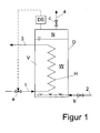
- FIG. 1 schematically illustrated embodiment.
- the exemplary embodiment shows an evaporator in a synthesis gas plant, in which liquid, cryogenic carbon monoxide is evaporated in indirect heat exchange with warm water.
- liquid carbon monoxide is introduced into the evaporator V, which is designed with a pressure vessel D.
- the pressure vessel D is filled with a water bath W, the nitrogen N is superimposed.
- the water bath W is maintained at a constant temperature of about 40 ° C.
- the water transfers the enthalpy necessary for the evaporation to the carbon monoxide flowing in the heating coil H, so that gaseous carbon monoxide leaves the evaporator V via line 3. If leakage occurs in the heating coil H, liquid carbon monoxide can pass into the warm water W, where it evaporates abruptly, the water W cools down and pressure in the pressure vessel D is increased.
- This increase in pressure is registered via the pressure switch DS, which outputs a signal when a predetermined limit pressure is exceeded, through which the equipped with an adjustment, arranged in the conduit 1 shut-off a closed and the supply of liquid carbon monoxide to the evaporator V is interrupted.
- the amount of low-pressure steam 2 is increased by the control member b and Heating power increased.
- the warmed carbon monoxide gas is then withdrawn via the control element c controlled from the pressure vessel D and fed via line 4 a torch (not shown) for disposal.
Landscapes
- Engineering & Computer Science (AREA)
- Physics & Mathematics (AREA)
- Thermal Sciences (AREA)
- Mechanical Engineering (AREA)
- General Engineering & Computer Science (AREA)
- Chemical & Material Sciences (AREA)
- Chemical Kinetics & Catalysis (AREA)
- Filling Or Discharging Of Gas Storage Vessels (AREA)
Applications Claiming Priority (1)
| Application Number | Priority Date | Filing Date | Title |
|---|---|---|---|
| DE200910005923 DE102009005923A1 (de) | 2009-01-23 | 2009-01-23 | Verfahren und Vorrichtung zur Ableitung von Leckagegas aus einem Verdampfer |
Publications (2)
| Publication Number | Publication Date |
|---|---|
| EP2211134A2 true EP2211134A2 (fr) | 2010-07-28 |
| EP2211134A3 EP2211134A3 (fr) | 2014-01-08 |
Family
ID=42154664
Family Applications (1)
| Application Number | Title | Priority Date | Filing Date |
|---|---|---|---|
| EP10000363.1A Withdrawn EP2211134A3 (fr) | 2009-01-23 | 2010-01-15 | Procédé et dispositif de dérivation de gaz de fuite d'un évaporateur |
Country Status (4)
| Country | Link |
|---|---|
| EP (1) | EP2211134A3 (fr) |
| CN (1) | CN102003621B (fr) |
| DE (1) | DE102009005923A1 (fr) |
| RU (1) | RU2511867C2 (fr) |
Citations (1)
| Publication number | Priority date | Publication date | Assignee | Title |
|---|---|---|---|---|
| DE102005003497A1 (de) | 2005-01-25 | 2006-07-27 | Linde Ag | Verfahren und Vorrichtung zur Zwischenspeicherung von Kohlenmonoxid in Synthesegasanlagen |
Family Cites Families (13)
| Publication number | Priority date | Publication date | Assignee | Title |
|---|---|---|---|---|
| FR2033567A5 (fr) * | 1969-02-27 | 1970-12-04 | Stein Industrie | |
| DE2255034B2 (de) * | 1972-11-10 | 1974-12-19 | Friedrich Uhde Gmbh, 4600 Dortmund | Verfahren zum mehrstufigen Konzentrieren von Alkalilauge |
| JPS5728940A (en) * | 1980-07-30 | 1982-02-16 | Hitachi Ltd | Monitoring device for contamination of heat exchanger |
| SU1610198A1 (ru) * | 1988-12-14 | 1990-11-30 | Специализированное Проектно-Конструкторское И Технологическое Бюро Специализированного Транспортного Управления По Очистке Городских Территорий И Водных Протоков Исполкома Ленгорсовета | Установка дл сжигани отходов |
| RU2079317C1 (ru) * | 1995-04-13 | 1997-05-20 | Закрытое Акционерное общество "ЭЛОРГ СТМ" | Генератор для установки газового пожаротушения |
| RU2090512C1 (ru) * | 1995-12-21 | 1997-09-20 | Борис Алексеевич Зимин | Установка для перегонки жидкостей и выпаривания растворов |
| JP3775920B2 (ja) * | 1998-04-23 | 2006-05-17 | 松下電器産業株式会社 | 空気調和機 |
| DE19960462C2 (de) * | 1999-12-15 | 2003-02-06 | Renzmann Und Gruenewald Gmbh | Verfahren zur Wiederholungsdruckprüfung von Doppelrohrsicherheitswärmeübertragern |
| US6506229B2 (en) * | 2001-01-08 | 2003-01-14 | Inco Limited | Two experimental trials using the system 10 demonstrate the efficacy of the present process: |
| CN1368007A (zh) * | 2001-02-08 | 2002-09-11 | 新疆皇朝果蔬发展有限公司 | So2气体熏蒸洗涤葡萄贮藏保鲜设备 |
| DE502006008159D1 (de) * | 2005-03-24 | 2010-12-09 | Ems Chemie Ag | Verwendung eines Leitungssystems für Fluide mit flüchtigen Bestandteilen |
| US8066023B2 (en) * | 2007-04-10 | 2011-11-29 | Black & Veatch Corporation | System and method for collecting and increasing the pressure of seal leak gas |
| DE102007041766B4 (de) * | 2007-09-04 | 2012-04-19 | Frank Triesch | Leckageüberwachung von Anlagen mit mindestens zwei Medienkreisläufen, insbesondere Wärmeübertragern |
-
2009
- 2009-01-23 DE DE200910005923 patent/DE102009005923A1/de not_active Withdrawn
-
2010
- 2010-01-15 EP EP10000363.1A patent/EP2211134A3/fr not_active Withdrawn
- 2010-01-22 RU RU2010102022/06A patent/RU2511867C2/ru active
- 2010-01-22 CN CN201010109230.3A patent/CN102003621B/zh active Active
Patent Citations (1)
| Publication number | Priority date | Publication date | Assignee | Title |
|---|---|---|---|---|
| DE102005003497A1 (de) | 2005-01-25 | 2006-07-27 | Linde Ag | Verfahren und Vorrichtung zur Zwischenspeicherung von Kohlenmonoxid in Synthesegasanlagen |
Also Published As
| Publication number | Publication date |
|---|---|
| CN102003621B (zh) | 2014-11-05 |
| CN102003621A (zh) | 2011-04-06 |
| EP2211134A3 (fr) | 2014-01-08 |
| DE102009005923A1 (de) | 2010-07-29 |
| RU2010102022A (ru) | 2011-07-27 |
| RU2511867C2 (ru) | 2014-04-10 |
Similar Documents
| Publication | Publication Date | Title |
|---|---|---|
| EP3017238B1 (fr) | Dispositif de refroidissement d'un dissipateur avec un liquide surrefroidi dans un circuit de refroidissement | |
| DE68926220T2 (de) | Verfahren und Vorrichtung zur Dampfkrafterzeugung | |
| DE69402624T2 (de) | Vorrichtung zur Lieferung von Hochdruckgas | |
| DE19717267B4 (de) | Verfahren zur Aufbereitung von tiefgekühltem Flüssiggas | |
| DE112015004382T5 (de) | Wasserstoffkraftstoffversorgungssystem | |
| EP3722652A1 (fr) | Récipient de stockage pour gaz liquéfié à très basse température | |
| DE3202279A1 (de) | Gasuebergabestation | |
| DE102014223626A1 (de) | Vorrichtung und Verfahren zur Rückgewinnung von Abwärmeenergie und ein Nutzkraftfahrzeug | |
| DE112022003973T5 (de) | Kryogenes sicherheitsbehältersystem | |
| EP2682569A1 (fr) | Procédé et dispositif destinés à la transformation d'énergie | |
| EP2667116B1 (fr) | Procédé et dispositif destinés au refroidissement | |
| EP2986910B1 (fr) | Système et procédé de préchauffage d'eau d'alimentation dans des centrales électriques à vapeur avec découplage de la vapeur de processus | |
| EP2326800A2 (fr) | Centrale à vapeur pour produire de l'énergie électrique | |
| EP4343247A1 (fr) | Procédé et dispositif de production de gaz d'air | |
| EP3594554A1 (fr) | Dispositif de sous-refroidissement des gaz liquéfiés | |
| EP1892457B1 (fr) | Procédé et dispositif destinés à l'enregistrement de gaz combustible, en particulier de gaz naturel | |
| DE102008032291A1 (de) | Vorrichtung und Verfahren zum Entgraten von Formteilen | |
| EP2211134A2 (fr) | Procédé et dispositif de dérivation de gaz de fuite d'un évaporateur | |
| DE102020001082A1 (de) | Vorrichtung und Verfahren zur Erzeugung eines temperierten, kalten Gasstroms | |
| EP4446680A2 (fr) | Procédé et dispositif de liquéfaction de gaz | |
| EP2679879B1 (fr) | Dispositif de surfusion de gaz liquides à bas point d'ébullition | |
| EP3662145B1 (fr) | Procédé amélioré de génération d'électricité lors de la regazéification d'un fluide par réduction de pression surcritique | |
| DE102018008011A1 (de) | Energiespeicherung mit kryogenen Fluiden | |
| DE102014105779A1 (de) | Dampf/Wasser-Wärmeübertragungseinrichtung | |
| EP1846691B1 (fr) | Procede et dispositif pour remplir des reservoirs sous pression avec des gaz ou des melanges de gaz non liquefies |
Legal Events
| Date | Code | Title | Description |
|---|---|---|---|
| PUAI | Public reference made under article 153(3) epc to a published international application that has entered the european phase |
Free format text: ORIGINAL CODE: 0009012 |
|
| AK | Designated contracting states |
Kind code of ref document: A2 Designated state(s): AT BE BG CH CY CZ DE DK EE ES FI FR GB GR HR HU IE IS IT LI LT LU LV MC MK MT NL NO PL PT RO SE SI SK SM TR |
|
| AX | Request for extension of the european patent |
Extension state: AL BA RS |
|
| PUAL | Search report despatched |
Free format text: ORIGINAL CODE: 0009013 |
|
| AK | Designated contracting states |
Kind code of ref document: A3 Designated state(s): AT BE BG CH CY CZ DE DK EE ES FI FR GB GR HR HU IE IS IT LI LT LU LV MC MK MT NL NO PL PT RO SE SI SK SM TR |
|
| AX | Request for extension of the european patent |
Extension state: AL BA RS |
|
| RIC1 | Information provided on ipc code assigned before grant |
Ipc: F17C 7/04 20060101ALI20131203BHEP Ipc: G01M 3/32 20060101ALI20131203BHEP Ipc: F28D 1/02 20060101AFI20131203BHEP Ipc: F28F 27/00 20060101ALI20131203BHEP Ipc: G01M 3/22 20060101ALI20131203BHEP Ipc: B01D 1/30 20060101ALI20131203BHEP |
|
| 17P | Request for examination filed |
Effective date: 20140703 |
|
| RBV | Designated contracting states (corrected) |
Designated state(s): AT BE BG CH CY CZ DE DK EE ES FI FR GB GR HR HU IE IS IT LI LT LU LV MC MK MT NL NO PL PT RO SE SI SK SM TR |
|
| 17Q | First examination report despatched |
Effective date: 20150129 |
|
| STAA | Information on the status of an ep patent application or granted ep patent |
Free format text: STATUS: THE APPLICATION IS DEEMED TO BE WITHDRAWN |
|
| 18D | Application deemed to be withdrawn |
Effective date: 20160419 |