EP2211189A2 - Multimètre numérique disposant d'un affichage distant avec une commutation automatique de mode de communication - Google Patents
Multimètre numérique disposant d'un affichage distant avec une commutation automatique de mode de communication Download PDFInfo
- Publication number
- EP2211189A2 EP2211189A2 EP09156905A EP09156905A EP2211189A2 EP 2211189 A2 EP2211189 A2 EP 2211189A2 EP 09156905 A EP09156905 A EP 09156905A EP 09156905 A EP09156905 A EP 09156905A EP 2211189 A2 EP2211189 A2 EP 2211189A2
- Authority
- EP
- European Patent Office
- Prior art keywords
- remote display
- display unit
- communication
- base unit
- multimeter
- Prior art date
- Legal status (The legal status is an assumption and is not a legal conclusion. Google has not performed a legal analysis and makes no representation as to the accuracy of the status listed.)
- Granted
Links
Images


Classifications
-
- G—PHYSICS
- G01—MEASURING; TESTING
- G01R—MEASURING ELECTRIC VARIABLES; MEASURING MAGNETIC VARIABLES
- G01R15/00—Details of measuring arrangements of the types provided for in groups G01R17/00 - G01R29/00, G01R33/00 - G01R33/26 or G01R35/00
- G01R15/12—Circuits for multi-testers, i.e. multimeters, e.g. for measuring voltage, current, or impedance at will
- G01R15/125—Circuits for multi-testers, i.e. multimeters, e.g. for measuring voltage, current, or impedance at will for digital multimeters
-
- G—PHYSICS
- G08—SIGNALLING
- G08C—TRANSMISSION SYSTEMS FOR MEASURED VALUES, CONTROL OR SIMILAR SIGNALS
- G08C17/00—Arrangements for transmitting signals characterised by the use of a wireless electrical link
- G08C17/02—Arrangements for transmitting signals characterised by the use of a wireless electrical link using a radio link
-
- G—PHYSICS
- G08—SIGNALLING
- G08C—TRANSMISSION SYSTEMS FOR MEASURED VALUES, CONTROL OR SIMILAR SIGNALS
- G08C23/00—Non-electrical signal transmission systems, e.g. optical systems
- G08C23/04—Non-electrical signal transmission systems, e.g. optical systems using light waves, e.g. infrared
-
- H—ELECTRICITY
- H04—ELECTRIC COMMUNICATION TECHNIQUE
- H04Q—SELECTING
- H04Q9/00—Arrangements in telecontrol or telemetry systems for selectively calling a substation from a main station, in which substation desired apparatus is selected for applying a control signal thereto or for obtaining measured values therefrom
-
- H—ELECTRICITY
- H04—ELECTRIC COMMUNICATION TECHNIQUE
- H04Q—SELECTING
- H04Q2209/00—Arrangements in telecontrol or telemetry systems
- H04Q2209/40—Arrangements in telecontrol or telemetry systems using a wireless architecture
Definitions
- the present invention relates generally to digital multimeters. More particularly, the invention relates to a digital multimeter having a remote display with automatic communication mode switching.
- Digital multimeters function to measure a number of electrical parameters as needed for service, troubleshooting and maintenance. Such parameters may include AC voltage and current, DC voltage and current, resistance and continuity. In some cases, a DMM may measure other parameters such as capacitance and temperature.
- a DMM will often be configured as a hand-held unit having a rotary knob by which various functions are selected.
- a plurality of lead jacks are provided in the case (i.e., housing) of the unit for connection of test leads. The specific jack used may depend on the function that has been selected.
- An LCD display provides a reading of the tested parameter. Details regarding the construction and operation of multimeters may be discerned from U.S. Pat. Nos. 7,034,517 , 6,466,003 and 6,043,640 , each of which is incorporated herein by reference in its entirety.
- a remote display separate from the DMM but linked by communication to the DMM, may be used to lessen this difficulty. Examples of remote displays are shown in U.S. Pub. No. 2003/0137310 to Holzel and U.S. Pat. No. 7,304,618 to Plathe .
- the remote display may use wireless coupling, such as infrared (IR) or radio frequency (RF), for communication with the DMM. While IR and RF are both effective, each has its limitations. RF utilizes a relatively high level of power, thus reducing battery life at the remote display. IR uses less power, but requires a line of sight between transmitter and receiver.
- IR infrared
- RF radio frequency
- the present invention provides a multimeter comprising a base unit having at least one test lead terminal.
- a remote display unit separate from the base unit is also provided.
- the remote display unit has a display operative to show measured parameters.
- the multimeter further comprises communication circuitry operative to provide electrical communication between the base unit and the remote display unit.
- the communication circuitry provides electrical communication in a plurality of alternative communication modes.
- At least two of the alternative communication modes are wireless communication modes.
- a first communication may be an optical communication mode (such as IR), whereas a second communication mode may be an RF communication mode.
- the communication circuitry provides electrical communication in a first communication mode when the remote display unit is located adjacent to the base unit and in a second communication mode when the remote display unit is located apart from the base unit. For example, the communication circuitry may first attempt to establish communication from the base unit in an IR communication mode and then switch to an RF communication mode if IR communication is unsuccessful.
- the remote display unit has an end surface canted at an acute angle relative to perpendicular such that the display will be tilted when the remote display unit is placed on a horizontal surface.
- the remote display unit may also be adapted to be placed on a vertical surface.
- an internal magnet may be utilized to retain the remote display unit on the vertical surface.
- the present invention provides a method of establishing electrical communication between a base unit and a separate remote display unit of an electrical test instrument.
- a request for response via an IR communication mode is sent to the other of the base unit and the remote display unit. If a response to the request for response is received, then communication is maintained in an optical communication mode. If a response to the request for response is not received, then communication is established in an RF communication mode.
- a further aspect of the present invention provides an electrical test instrument comprising a base unit and a remote display unit separate from but matable with the base unit.
- the remote display unit has a display operative to show measured parameters.
- the electrical test instrument further comprises communication circuitry operative to provide electrical communication between the base unit and the remote display unit.
- the communication circuitry is operative to provide electrical communication in a first communication mode when the remote display unit is mated with the base unit and a second communication mode when the remote display unit is located apart from the base unit.
- a multimeter comprising a base unit having a plurality of test lead jacks and a rotary selector knob.
- a remote display unit separate from but matable with the base unit is also provided.
- the remote display unit has a display operative to show measured parameters.
- the multimeter further includes communication circuitry operative to provide electrical communication between the base unit and the remote display unit.
- the communication circuitry is operative to provide electrical communication in a first communication mode when the remote display unit is mated with the base unit and a second communication mode when the remote display unit is located apart from the base unit.
- the first and second communication modes are wireless communication modes.
- Figure 1 is a top perspective view of a DMM constructed in accordance with an embodiment of the present invention
- Figure 2 is a top plan view of the DMM of Figure 1 ;
- Figure 3 is a side elevational view of the DMM of Figure 1 ;
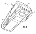
- Figure 4 is a bottom perspective view of the DMM of Figure 1 ;
- Figure 5 illustrates the characters that may appear on the DMM's display in accordance with the embodiment of Figure 1 ;
- Figure 6 is a diagrammatic representation showing test leads of a DMM connected to a circuit under test
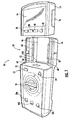
- Figure 7 is a perspective view of the DMM of Figure 1 showing separation of the remote display unit
- Figure 8 illustrates the manner in which the retaining mechanism may be released for separation of the remote display unit
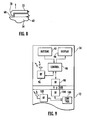
- Figure 9 is a diagrammatic representation showing communication between the remote display unit and base unit when the remote display unit is mated with the base unit;
- Figures 10 and 11 are flowcharts respectively showing the manner in which the base unit and the remote display unit select a communication mode
- Figure 12 shows the remote display unit placed on a flat surface, such as a shelf or table top
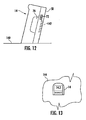
- Figure 13 shows the remote display unit attached to a vertical surface.
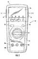
- FIGS 1 through 4 illustrate a digital multimeter (DMM) 10 constructed in accordance with an embodiment of the present invention.
- Multimeter 10 comprises a base unit 12 and a remote display unit 14.
- the housing of base unit 12 defines an interior cavity in which various internal components are located.
- the housing of base unit 12 is preferably formed having two or more housing members which are assembled together to form the interior cavity.
- these housing members may be molded of high impact rigid plastic material. In some cases, it may be desirable to overmold a softer polymeric material on at least portions of the rigid plastic material to enhance gripability and user comfort.
- remote display unit 14 is mated to base unit 12 such that its display 16 will be located in a conventional position on the overall DMM.
- Display 16 which will typically be an LCD display located behind a transparent window, shows a variety of information of interest to the user.
- display 16 will include a backlight that may be activated when desired to facilitate use in low-light conditions.
- Figure 5 depicts various characters (both numeric and symbolic) that may appear on display 16 depending on the operating mode of the DMM and other factors.
- the primary icons are a 4-digit, 7-segment numeric display.
- the measurement annunciators which indicate the units of measurement displayed by the numbers.
- the bottom right and left icons indicate a low battery condition with the remote unit and base unit, respectively.
- Auto Range and Manual Range indicate the meter ranging condition.
- the icons on the top left indicate the display modes and the icon on the top right indicates RF communication mode.
- the lighting bolt indicates a predetermined high voltage on the test leads.
- Base unit 12 includes a rotary selector knob 18 which allows the user to select a particular multimeter function. For example, 5-10 such functions may be indicated by respective stop positions in the knob rotation. As one skilled in the art will appreciate, suitable graphics will typically be printed on the top surface of the base unit housing to indicate the respective functions.
- Base unit 12 also includes a plurality of jacks 20a-c for connection of respective test leads.
- two test leads are connected to a respective two of lead jacks 20a-c depending on the parameter being tested.
- Figure 6 shows a pair of test leads 22 and 24 connected to a circuit 26 under test.
- DMM 10 preferably has test lead holders 28 and 30 defined on the bottom of base unit 12.
- Test lead holders 28 and 30 may be configured to retain the test leads in two orientations: (1) a storage orientation in which the leads are nested; and (2) a "third hand” orientation in which the terminal end of a test lead extends away from the DMM housing.
- base unit 12 can be used to maintain the lead's terminal end in position on one side of circuit 26 under test while the user positions the other test lead. This leaves the user's second hand free to operate the DMM.
- DMM 10 may include a shift key 32 located on base unit 12. Shift key 32 allows the user to select alternate functions for respective positions of selector knob 18. A high voltage indicator light 34 alerts a user who may not be viewing the remote display unit 14 (when separated from base unit 12) that the test lead has encountered a high voltage situation.
- buttons are also provided on remote display unit 14 itself. Typically, these buttons will relate to functions dealing directly with the display rather than the operating parameters of DMM 10.
- buttons will relate to functions dealing directly with the display rather than the operating parameters of DMM 10.
- One skilled in the art will appreciate, however, that variations of the present invention are possible in which different user interface elements are placed on base unit 12 and/or remote display unit 14. For example, in some embodiments, it may be desirable not to have any selector buttons on remote display 14.
- buttons are provided on remote display unit 14: hold button 36, min/max button 38, range button 40 and backlight button 42.
- backlight button 42 activates the internal light used to illuminate the LCD display.
- min/max button 38 causes the display to enter the min/max mode. In this mode, the meter captures the smallest reading and the largest reading. These readings can be displayed by toggling min/max button 38. Holding the button for a couple of seconds returns the meter to normal display mode.
- Pressing range button 40 puts the meter in manual range mode. Subsequent presses manually change the measurement range of the meter. Holding range button 40 for a couple of seconds returns the meter to autorange mode.
- FIG. 7 shows the manner in which remote display unit 14 is removed from base unit 12 in the illustrated embodiment.
- base unit 12 defines a receiving portion 50 at which remote display unit 14 is mated.
- Receiving portion 50 defines a pair of lateral rails 52 and 54 located on either side of a recess 56.
- the back of remote display unit 14 is generally complimentary to the configuration of receiving portion 50.
- remote display unit 14 includes a back portion 58 adapted to be slidably received in recess portion 56.
- a suitable latching mechanism is preferably provided to retain remote display unit 14 with respect to base unit 12.
- the latching mechanism is easily releasable by the user.
- rails 52 and 54 include respective flanges 60 and 62 extending part of the way along their length.
- flanges 60 and 62 terminate before reaching wall 64 of base unit 12 to define respective gaps 66 and 68.
- gap 68 receives the end projection 70 of a spring-loaded latching arm 72 carried by the remote display unit 14. End projection 70 thus retains remote display unit 14 in position by engaging the end surface of flange 62.
- a similar latching arm is associated with the other flange 60.
- buttons 74 and 76 located on the respective sides of remote display unit 12 (as indicated by arrows S in Figure 2 ). Release buttons 74 and 76 are operatively connected to an associated latching arm, thus causing the latching to move inward (and away from its corresponding flange 60 or 62 on base unit 12). The user can then simply slide remote display unit 14 until it is completely separated from base unit 12.
- DMM 10 is preferably operable to switch between first and second communication modes depending on whether remote display unit 14 is mated or separated with respect to base unit 12.
- remote display unit 14 will preferably communicate with base unit 12 using RF communication when the two units are separated from each other.
- RF communication is advantageous because it does not require a direct line of sight between base unit 12 and remote display unit 14.
- DMM 10 is adapted to switch to a lower power mode of communication when remote display unit 14 is attached to base unit 12. In this embodiment, for example, DMM 10 utilizes IR communication when remote display unit 14 is mated.
- the present embodiment utilizes two different types of wireless communication depending on whether or not remote display unit 14 is separated from base unit 12.
- direct electrical connection can alternatively be used when remote display unit 14 is docked.
- a mechanical switch can be used to achieve communication mode switching. Often, however, it will be preferable to use logical methodology to determine whether remote display unit 14 is mated with or separated from base unit 12.
- remote display unit 14 includes control circuitry 90, which receives inputs from buttons 92 and provides information to display 94. Control circuitry 90 also selects whether to communicate with base unit 12 via RF transceiver 96 or IR interface 98.
- RF transceiver 96 may include any circuit components necessary in order to effect RF communication with base unit 12. These may include a digital-to-analog converter, frequency generator, modulator and antenna.
- IR interface 98 will include components necessary for IR communication, such as an IR-LED and photodetector.
- control circuitry 90 may be implemented in hardware, firmware, software, or a combination thereof as necessary or desirable.
- Base unit 12 will likewise include circuit elements used in communicating with remote display unit 14.
- control circuitry 100 (which may be implemented as hardware, firmware, software, or a combination thereof) is in electrical communication with an RF transceiver 102 and IR interface 104. Control circuitry 100 determines whether communication with remote display unit 14 should occur by RF transceiver 102 or IR interface 104.
- both base unit 12 and remote display unit 14 are preferably equipped with an IR transmissive window, such as window 106 of base unit 12 ( Fig. 7 ), which are aligned when remote display unit 14 is mated in order to provide the desired line of sight between IR interface 98 and IR interface 104 (as shown at 108 in Fig. 9 ).
- an IR transmissive window such as window 106 of base unit 12 ( Fig. 7 )
- FIGS 10 and 11 illustrate respective processes that may be performed by control circuitry 100 and control circuitry 90 in order to switch communication between RF and IR modes as described above.
- the process implemented by control circuitry 100 begins as indicated at 110. Initially, the "radio" will be off (as indicated at 112), meaning that there will be no RF communication as this point.
- base unit 12 next "pings" remote display unit 14 via the IR interface.
- control circuitry 100 waits for a predetermined period of time for a response from remote display unit 14. If the remote display unit 14 responds, IR communication rather than RF communication will be utilized as indicated at 118. On the other hand, if remote display unit 14 does not respond to the "ping," it is assumed that remote display unit 14 is separated from base unit 12. In this case, as indicated at 120, RF communication will be utilized rather than IR communication.
- a similar process occurs at control circuitry 90 of remote display unit 14.
- the process starts as indicated at 120. Initially, the process assumes a "radio on” condition, meaning that communication will occur via RF (as indicated at 122). Nevertheless, the process will continually listen for a "ping" via IR, as indicated at 124. Decision block 126 asks whether or not a ping is "heard.” If a ping is heard, as indicated as 128, RF communication is switched off and IR communication will be utilized. On the other hand, if no ping is heard, the radio will remain on and RF communication will be utilized as indicated at 130.
- remote display unit 14 the physical interface between the end surface of remote display unit 14 and wall 64 of base unit 12 is situated at a small angle ⁇ relative to the vertical. As shown in Figure 12 , this is advantageous because it will produce a slight tilt when remote display unit 14 is placed on a horizontal surface 140, such as a shelf or table. This tilt facilitates viewing by a user whose eye level will typically be higher than that of surface 140.
- remote display unit 14 may be adapted for attachment to a vertical surface.
- remote display unit 14 includes a magnet 142 located at back portion 58.
- Magnet 142 may be located inside of a removable door used to cover the battery compartment of remote display unit 14. As shown in Figure 13 , magnet 142 allows remote display unit 14 to be placed on any vertical surface 144 having suitable ferrous characteristics.
- the present invention provides a digital multimeter having a remote display with automatic communication mode switching. While preferred embodiments of the invention have been shown and described, modifications and variations may be made thereto by those of ordinary skill in the art without departing from the spirit and scope of the present invention. In addition, it should be understood that aspects of the various embodiments may be interchanged both in whole or in part. Furthermore, those of ordinary skill in the art will appreciate that the foregoing description is by way of example only, and is not intended to be limitative of the invention as further described in the appended claims.
- An electrical test instrument comprises:
- optical communication mode is an IR communication mode.
- An electrical test instrument as set forth above, further comprising a latching mechanism which releasably retains said remote display unit in mated relationship with said base unit.
- a multimeter comprising:
- optical communication mode is an IR communication mode
Landscapes
- Physics & Mathematics (AREA)
- General Physics & Mathematics (AREA)
- Engineering & Computer Science (AREA)
- Computer Networks & Wireless Communication (AREA)
- Measuring Instrument Details And Bridges, And Automatic Balancing Devices (AREA)
- Arrangements For Transmission Of Measured Signals (AREA)
Applications Claiming Priority (1)
| Application Number | Priority Date | Filing Date | Title |
|---|---|---|---|
| US12/356,885 US8358121B2 (en) | 2009-01-21 | 2009-01-21 | Digital multimeter having remote display with automatic communication mode switching |
Publications (3)
| Publication Number | Publication Date |
|---|---|
| EP2211189A2 true EP2211189A2 (fr) | 2010-07-28 |
| EP2211189A3 EP2211189A3 (fr) | 2012-12-26 |
| EP2211189B1 EP2211189B1 (fr) | 2018-09-19 |
Family
ID=41666444
Family Applications (1)
| Application Number | Title | Priority Date | Filing Date |
|---|---|---|---|
| EP09156905.3A Active EP2211189B1 (fr) | 2009-01-21 | 2009-03-31 | Multimètre numérique disposant d'un affichage distant avec une commutation automatique de mode de communication |
Country Status (3)
| Country | Link |
|---|---|
| US (1) | US8358121B2 (fr) |
| EP (1) | EP2211189B1 (fr) |
| CN (1) | CN101782600A (fr) |
Cited By (1)
| Publication number | Priority date | Publication date | Assignee | Title |
|---|---|---|---|---|
| WO2014074208A1 (fr) * | 2012-11-07 | 2014-05-15 | Eaton Corporation | Dispositif et système de surveillance de jonctions électriques |
Families Citing this family (38)
| Publication number | Priority date | Publication date | Assignee | Title |
|---|---|---|---|---|
| US8004272B2 (en) * | 2009-03-11 | 2011-08-23 | Fluke Corporation | Digital multimeter having visible light communication port |
| KR101598336B1 (ko) * | 2009-05-29 | 2016-02-29 | 엘지전자 주식회사 | 공간리모콘의 페어링방법 및 동작방법 |
| US20100306688A1 (en) * | 2009-06-01 | 2010-12-02 | Cho Su Yeon | Image display device and operation method therefor |
| US8704958B2 (en) * | 2009-06-01 | 2014-04-22 | Lg Electronics Inc. | Image display device and operation method thereof |
| KR101572843B1 (ko) * | 2009-06-03 | 2015-11-30 | 엘지전자 주식회사 | 영상 표시 장치 및 그 동작 방법 |
| US8856555B2 (en) | 2009-07-17 | 2014-10-07 | Fluke Corporation | Power state coordination for portable test tools |
| US8755173B2 (en) * | 2009-08-03 | 2014-06-17 | Fluke Corporation | Digital multimeters including a ruggedized jacket |
| USD625633S1 (en) * | 2009-08-03 | 2010-10-19 | Fluke Corporation | Digital multimeter including a jacket |
| US8374507B2 (en) * | 2009-09-18 | 2013-02-12 | Fluke Corporation | Digital multimeter having remote display with automatic communication binding |
| US8405380B2 (en) | 2009-09-28 | 2013-03-26 | Fluke Corporation | Digital multimeters including a remote display |
| USD634227S1 (en) * | 2009-09-28 | 2011-03-15 | Fluke Corporation | Digital multimeter including a remote display, the body for the digital multimeter including a remote display, and the head for the digital multimeter including a remote display |
| US20110193548A1 (en) * | 2010-02-05 | 2011-08-11 | Appa Technology Corp. | Separation-type avometer |
| US9615147B2 (en) * | 2010-05-17 | 2017-04-04 | Flir Systems, Inc. | Multisensory meter system |
| USD684073S1 (en) * | 2012-01-27 | 2013-06-11 | Fluke Corporation | Digital multimeter with wireless transmitter |
| US10095659B2 (en) | 2012-08-03 | 2018-10-09 | Fluke Corporation | Handheld devices, systems, and methods for measuring parameters |
| WO2014047843A1 (fr) * | 2012-09-27 | 2014-04-03 | 深圳华盛昌机械实业有限公司 | Procédé et dispositif de mesure et d'enregistrement d'un paramètre électrique |
| WO2014063042A1 (fr) | 2012-10-19 | 2014-04-24 | Milwaukee Electric Tool Corporation | Dispositif d'examen visuel |
| USD726047S1 (en) | 2013-02-05 | 2015-04-07 | Fluke Corporation | Main Body for a data logger |
| CN105408898B (zh) | 2013-03-15 | 2019-05-28 | 弗兰克公司 | 测量数据的自动记录和图形生成 |
| US9568504B2 (en) | 2013-03-15 | 2017-02-14 | Milwaukee Electric Tool Corporation | Digital multi-meter |
| USD723401S1 (en) | 2013-06-19 | 2015-03-03 | Danaher (Shanghai) Industrial Instrumentation Technologies R&D Co., Ltd. | Digital multimeter |
| USD724454S1 (en) * | 2013-06-19 | 2015-03-17 | Danaher (Shanghai) Industrial Instrumentation Technologies R&D Co., Ltd. | Digital multimeter |
| USD723959S1 (en) | 2013-06-19 | 2015-03-10 | Danaher (Shanghai) Industrial Instrumentation Technologies R&D Co., Ltd. | Digital multimeter |
| USD712764S1 (en) * | 2013-06-25 | 2014-09-09 | Flir Systems, Inc. | Meter |
| USD713275S1 (en) * | 2013-06-25 | 2014-09-16 | Flir Systems, Inc. | Meter |
| USD719040S1 (en) * | 2013-07-12 | 2014-12-09 | Milwaukee Electric Tool Corporation | Electrical tester |
| US9739801B2 (en) * | 2013-07-16 | 2017-08-22 | Fluke Corporation | Analytical gateway device for measurement devices |
| USD724976S1 (en) | 2013-12-31 | 2015-03-24 | Milwaukee Electric Tool Corporation | Electrical tester |
| US9664708B2 (en) | 2014-01-09 | 2017-05-30 | Milwaukee Electric Tool Corporation | Test and measurement device including grooves for receiving probes in a use position |
| US9509364B2 (en) * | 2014-10-01 | 2016-11-29 | Amphenol Antenna Solutions, Inc. | Integrated antenna unit with field replaceable frequency specific devices |
| CN104236441A (zh) * | 2014-10-04 | 2014-12-24 | 胡达广 | 分体式测量工具 |
| US10630034B2 (en) | 2015-05-27 | 2020-04-21 | Amphenol Corporation | Integrated antenna unit with blind mate interconnect |
| CN105490695A (zh) * | 2015-11-23 | 2016-04-13 | 国网重庆市电力公司电力科学研究院 | 一种可穿戴式测量仪 |
| JP6690473B2 (ja) * | 2016-08-30 | 2020-04-28 | オムロン株式会社 | 計測装置およびその制御方法、並びに制御プログラム |
| USD853258S1 (en) * | 2017-05-09 | 2019-07-09 | Lin Xiaohong | Multifunctional multimeter |
| US11346858B1 (en) * | 2020-12-18 | 2022-05-31 | Product Line Design Llc | Electrical circuit bypass device |
| US20240319237A1 (en) | 2023-03-23 | 2024-09-26 | Fluke Corporation | Multi-channel handheld digital multimeter having separate common terminals |
| USD1120785S1 (en) * | 2023-12-29 | 2026-03-31 | Fluke Corporation | Multimeter |
Citations (5)
| Publication number | Priority date | Publication date | Assignee | Title |
|---|---|---|---|---|
| US6043640A (en) | 1997-10-29 | 2000-03-28 | Fluke Corporation | Multimeter with current sensor |
| US6466003B1 (en) | 1998-06-30 | 2002-10-15 | Fluke Corporation | Microamp measurement for two-terminal digital meter |
| US20030137310A1 (en) | 2002-01-22 | 2003-07-24 | Thomas Holzel | Remote viewing screen for test instrument |
| US7034517B2 (en) | 2004-03-15 | 2006-04-25 | Fluke Corporation | Multimeter with filtered measurement mode |
| US7304618B2 (en) | 2003-02-14 | 2007-12-04 | Plathe Henry J | Remote display for portable meter |
Family Cites Families (28)
| Publication number | Priority date | Publication date | Assignee | Title |
|---|---|---|---|---|
| FR2537272B1 (fr) | 1982-12-03 | 1986-04-04 | Solomat Sa | Appareil de mesure multi-sondes |
| US4942356A (en) * | 1988-05-12 | 1990-07-17 | Snap-On Tools Corporation | Modular electronic device |
| US5640155A (en) | 1992-02-18 | 1997-06-17 | O'connor Springer | Meter cradle with wireless communication port |
| US5880867A (en) | 1996-03-29 | 1999-03-09 | Intermec Ip Corp. | Infrared backbone communication network having a radio frequency backup channel |
| US6035350A (en) | 1997-01-21 | 2000-03-07 | Dell Usa, L.P. | Detachable I/O device with built-in RF/IR functionality to facilitate remote audio-visual presentation |
| US6353313B1 (en) | 1997-09-11 | 2002-03-05 | Comsonics, Inc. | Remote, wireless electrical signal measurement device |
| US6568848B1 (en) | 1999-09-20 | 2003-05-27 | Maverick Industries, Inc. | Wireless remote cooking thermometer system |
| US6436038B1 (en) | 2000-08-11 | 2002-08-20 | Clarissa Engstrom | Animal vital signs monitoring system |
| US6944402B1 (en) * | 2000-11-18 | 2005-09-13 | Tribeam Technologies, Inc. | Extended range infrared communication (ERIC) for an infrared associated (IrDA) compliant portable device |
| US6784855B2 (en) | 2001-02-15 | 2004-08-31 | Microsoft Corporation | Methods and systems for a portable, interactive display device for use with a computer |
| US6812685B2 (en) * | 2001-03-22 | 2004-11-02 | Actuant Corporation | Auto-selecting, auto-ranging contact/noncontact voltage and continuity tester |
| US6912379B2 (en) * | 2002-03-21 | 2005-06-28 | Taiwan Security Net Co., Ltd. | Infrared ray transmitting and receiving device having a signal communicator |
| US20030184515A1 (en) * | 2002-04-02 | 2003-10-02 | Huo-Lu Tsai | Computer user input assembly with wired and wireless transmission capability |
| US7109700B2 (en) | 2003-05-30 | 2006-09-19 | David Fazzina | Multimeter having off-device display device and selection device |
| KR100524018B1 (ko) | 2003-07-25 | 2005-10-26 | 삼성전자주식회사 | 이동형 디스플레이장치 및 이동형 디스플레이 시스템 |
| DE602004016115D1 (de) | 2004-04-08 | 2008-10-09 | Accenture Global Services Gmbh | Verfahren und Vorrichtung zur entfernten Überwachung eines Messgerät |
| US7355523B2 (en) | 2004-04-15 | 2008-04-08 | Alberto Sid | Remote controlled intelligent lighting system |
| TWM257451U (en) | 2004-06-15 | 2005-02-21 | Der Ee Electrical Instr Co Ltd | Multi-purposed electric meter with wireless control and measurement |
| GB0413746D0 (en) | 2004-06-19 | 2004-07-21 | Atomic Energy Authority Uk | Wireless probe |
| US7075289B2 (en) | 2004-07-27 | 2006-07-11 | Der Ee Electrical Instrument Co., Ltd. | Wireless remote control measuring multipurpose meter |
| DE202004011873U1 (de) | 2004-07-29 | 2004-11-04 | DER EE ELECTRICAL INSTRUMENT CO., LTD., Yung Ho | Drahtlos fernbedienbarer Vielfunktionsstrommesser |
| FR2873839B3 (fr) | 2004-07-30 | 2006-11-17 | Der Ee Electrical Instr Co | Poste multifonction de mesure a distance |
| US7675683B2 (en) | 2004-09-22 | 2010-03-09 | Motion Research Corporation | Ambient light display and system for displaying data |
| US7382272B2 (en) | 2005-10-19 | 2008-06-03 | Schweitzer Engineering Laboratories, Inc. | System, a tool and method for communicating with a faulted circuit indicator using a remote display |
| US20080143317A1 (en) | 2006-12-19 | 2008-06-19 | Lecroy Corporation | Resizable display |
| US20080231256A1 (en) | 2006-12-19 | 2008-09-25 | Lecroy Corporation | Removable Front Panel Control for Oscilloscope |
| US8552843B2 (en) | 2008-02-12 | 2013-10-08 | Smk Manufacturing | Universal remote controller having home automation function |
| US8374507B2 (en) | 2009-09-18 | 2013-02-12 | Fluke Corporation | Digital multimeter having remote display with automatic communication binding |
-
2009
- 2009-01-21 US US12/356,885 patent/US8358121B2/en active Active
- 2009-03-31 EP EP09156905.3A patent/EP2211189B1/fr active Active
- 2009-04-10 CN CN200910134310A patent/CN101782600A/zh active Pending
Patent Citations (5)
| Publication number | Priority date | Publication date | Assignee | Title |
|---|---|---|---|---|
| US6043640A (en) | 1997-10-29 | 2000-03-28 | Fluke Corporation | Multimeter with current sensor |
| US6466003B1 (en) | 1998-06-30 | 2002-10-15 | Fluke Corporation | Microamp measurement for two-terminal digital meter |
| US20030137310A1 (en) | 2002-01-22 | 2003-07-24 | Thomas Holzel | Remote viewing screen for test instrument |
| US7304618B2 (en) | 2003-02-14 | 2007-12-04 | Plathe Henry J | Remote display for portable meter |
| US7034517B2 (en) | 2004-03-15 | 2006-04-25 | Fluke Corporation | Multimeter with filtered measurement mode |
Cited By (2)
| Publication number | Priority date | Publication date | Assignee | Title |
|---|---|---|---|---|
| WO2014074208A1 (fr) * | 2012-11-07 | 2014-05-15 | Eaton Corporation | Dispositif et système de surveillance de jonctions électriques |
| US9013189B2 (en) | 2012-11-07 | 2015-04-21 | Eaton Corporation | Electrical joint monitoring device and electrical joint monitoring system employing the same |
Also Published As
| Publication number | Publication date |
|---|---|
| US8358121B2 (en) | 2013-01-22 |
| EP2211189B1 (fr) | 2018-09-19 |
| CN101782600A (zh) | 2010-07-21 |
| US20100181990A1 (en) | 2010-07-22 |
| EP2211189A3 (fr) | 2012-12-26 |
Similar Documents
| Publication | Publication Date | Title |
|---|---|---|
| EP2211189B1 (fr) | Multimètre numérique disposant d'un affichage distant avec une commutation automatique de mode de communication | |
| US8374507B2 (en) | Digital multimeter having remote display with automatic communication binding | |
| US8405380B2 (en) | Digital multimeters including a remote display | |
| US12007526B2 (en) | Wall scanner | |
| AU767415B2 (en) | Detection of flip closure state of a flip phone | |
| US9423417B2 (en) | Voltage tester having alternatively attachable or separable probes | |
| US20090206859A1 (en) | Probe device having a light source thereon | |
| GB2494584A (en) | Infrared thermometer with pistol grip handle and rechargeable battery pack | |
| US20100299091A1 (en) | Multi-function portable electronic device | |
| EP2581749B1 (fr) | Testeur de tension ayant des sondes attachées ou séparables | |
| CN102565489A (zh) | 一种遥控电子万用表 | |
| US20080018426A1 (en) | Remote controlled power switch system | |
| CN117268583A (zh) | 一种数字化食物温度智能探测装置 | |
| CN215812990U (zh) | 触摸型智能数字万用表结构 | |
| CN219348002U (zh) | 一种插入式窖池温度检测装置 | |
| CN103078648A (zh) | 按键采集电路 | |
| CN109547778B (zh) | 机顶盒测试装置 | |
| KR100669606B1 (ko) | 충전기가 내장된 이동통신 단말기의 충전 방법 | |
| JPH05172887A (ja) | 無線検相装置 | |
| JP2010130381A (ja) | ダウンコンバータ装置および測定システム | |
| EP2312810A1 (fr) | Dispositif terminal de communication, procédé de commande d'éclairage et programme de commande d'éclairage | |
| CN105496348A (zh) | 一种游戏视力检测装置 |
Legal Events
| Date | Code | Title | Description |
|---|---|---|---|
| PUAI | Public reference made under article 153(3) epc to a published international application that has entered the european phase |
Free format text: ORIGINAL CODE: 0009012 |
|
| AK | Designated contracting states |
Kind code of ref document: A2 Designated state(s): AT BE BG CH CY CZ DE DK EE ES FI FR GB GR HR HU IE IS IT LI LT LU LV MC MK MT NL NO PL PT RO SE SI SK TR |
|
| AX | Request for extension of the european patent |
Extension state: AL BA RS |
|
| PUAL | Search report despatched |
Free format text: ORIGINAL CODE: 0009013 |
|
| AK | Designated contracting states |
Kind code of ref document: A3 Designated state(s): AT BE BG CH CY CZ DE DK EE ES FI FR GB GR HR HU IE IS IT LI LT LU LV MC MK MT NL NO PL PT RO SE SI SK TR |
|
| AX | Request for extension of the european patent |
Extension state: AL BA RS |
|
| RIC1 | Information provided on ipc code assigned before grant |
Ipc: G08C 19/02 20060101ALI20121122BHEP Ipc: G01R 15/12 20060101AFI20121122BHEP |
|
| 17P | Request for examination filed |
Effective date: 20130626 |
|
| AKX | Designation fees paid |
Designated state(s): DE ES FR GB IT |
|
| STAA | Information on the status of an ep patent application or granted ep patent |
Free format text: STATUS: EXAMINATION IS IN PROGRESS |
|
| 17Q | First examination report despatched |
Effective date: 20170712 |
|
| REG | Reference to a national code |
Ref country code: DE Ref legal event code: R079 Ref document number: 602009054562 Country of ref document: DE Free format text: PREVIOUS MAIN CLASS: G01R0015120000 Ipc: H04Q0009000000 |
|
| GRAP | Despatch of communication of intention to grant a patent |
Free format text: ORIGINAL CODE: EPIDOSNIGR1 |
|
| STAA | Information on the status of an ep patent application or granted ep patent |
Free format text: STATUS: GRANT OF PATENT IS INTENDED |
|
| RIC1 | Information provided on ipc code assigned before grant |
Ipc: G01R 15/12 20060101ALI20180312BHEP Ipc: G08C 23/04 20060101ALI20180312BHEP Ipc: G08C 17/02 20060101ALI20180312BHEP Ipc: H04Q 9/00 20060101AFI20180312BHEP |
|
| INTG | Intention to grant announced |
Effective date: 20180410 |
|
| GRAS | Grant fee paid |
Free format text: ORIGINAL CODE: EPIDOSNIGR3 |
|
| GRAA | (expected) grant |
Free format text: ORIGINAL CODE: 0009210 |
|
| STAA | Information on the status of an ep patent application or granted ep patent |
Free format text: STATUS: THE PATENT HAS BEEN GRANTED |
|
| AK | Designated contracting states |
Kind code of ref document: B1 Designated state(s): DE ES FR GB IT |
|
| REG | Reference to a national code |
Ref country code: GB Ref legal event code: FG4D |
|
| REG | Reference to a national code |
Ref country code: DE Ref legal event code: R096 Ref document number: 602009054562 Country of ref document: DE |
|
| PG25 | Lapsed in a contracting state [announced via postgrant information from national office to epo] |
Ref country code: IT Free format text: LAPSE BECAUSE OF FAILURE TO SUBMIT A TRANSLATION OF THE DESCRIPTION OR TO PAY THE FEE WITHIN THE PRESCRIBED TIME-LIMIT Effective date: 20180919 Ref country code: ES Free format text: LAPSE BECAUSE OF FAILURE TO SUBMIT A TRANSLATION OF THE DESCRIPTION OR TO PAY THE FEE WITHIN THE PRESCRIBED TIME-LIMIT Effective date: 20180919 |
|
| REG | Reference to a national code |
Ref country code: DE Ref legal event code: R097 Ref document number: 602009054562 Country of ref document: DE |
|
| PLBE | No opposition filed within time limit |
Free format text: ORIGINAL CODE: 0009261 |
|
| STAA | Information on the status of an ep patent application or granted ep patent |
Free format text: STATUS: NO OPPOSITION FILED WITHIN TIME LIMIT |
|
| 26N | No opposition filed |
Effective date: 20190620 |
|
| PGFP | Annual fee paid to national office [announced via postgrant information from national office to epo] |
Ref country code: GB Payment date: 20260327 Year of fee payment: 18 |
|
| PGFP | Annual fee paid to national office [announced via postgrant information from national office to epo] |
Ref country code: DE Payment date: 20260327 Year of fee payment: 18 |
|
| PGFP | Annual fee paid to national office [announced via postgrant information from national office to epo] |
Ref country code: FR Payment date: 20260325 Year of fee payment: 18 |