EP2211216B1 - Coupleur de pompe monolytique pour guide optique amplificateur avec rapport largeur/hauteur élevé - Google Patents
Coupleur de pompe monolytique pour guide optique amplificateur avec rapport largeur/hauteur élevé Download PDFInfo
- Publication number
- EP2211216B1 EP2211216B1 EP10151169A EP10151169A EP2211216B1 EP 2211216 B1 EP2211216 B1 EP 2211216B1 EP 10151169 A EP10151169 A EP 10151169A EP 10151169 A EP10151169 A EP 10151169A EP 2211216 B1 EP2211216 B1 EP 2211216B1
- Authority
- EP
- European Patent Office
- Prior art keywords
- pump
- coupler
- fiber
- section
- core
- Prior art date
- Legal status (The legal status is an assumption and is not a legal conclusion. Google has not performed a legal analysis and makes no representation as to the accuracy of the status listed.)
- Active
Links
Images




Classifications
-
- G—PHYSICS
- G02—OPTICS
- G02B—OPTICAL ELEMENTS, SYSTEMS OR APPARATUS
- G02B6/00—Light guides; Structural details of arrangements comprising light guides and other optical elements, e.g. couplings
- G02B6/24—Coupling light guides
- G02B6/26—Optical coupling means
- G02B6/28—Optical coupling means having data bus means, i.e. plural waveguides interconnected and providing an inherently bidirectional system by mixing and splitting signals
- G02B6/2804—Optical coupling means having data bus means, i.e. plural waveguides interconnected and providing an inherently bidirectional system by mixing and splitting signals forming multipart couplers without wavelength selective elements, e.g. "T" couplers, star couplers
-
- H—ELECTRICITY
- H01—ELECTRIC ELEMENTS
- H01S—DEVICES USING THE PROCESS OF LIGHT AMPLIFICATION BY STIMULATED EMISSION OF RADIATION [LASER] TO AMPLIFY OR GENERATE LIGHT; DEVICES USING STIMULATED EMISSION OF ELECTROMAGNETIC RADIATION IN WAVE RANGES OTHER THAN OPTICAL
- H01S3/00—Lasers, i.e. devices using stimulated emission of electromagnetic radiation in the infrared, visible or ultraviolet wave range
- H01S3/02—Constructional details
- H01S3/04—Arrangements for thermal management
- H01S3/042—Arrangements for thermal management for solid state lasers
-
- H—ELECTRICITY
- H01—ELECTRIC ELEMENTS
- H01S—DEVICES USING THE PROCESS OF LIGHT AMPLIFICATION BY STIMULATED EMISSION OF RADIATION [LASER] TO AMPLIFY OR GENERATE LIGHT; DEVICES USING STIMULATED EMISSION OF ELECTROMAGNETIC RADIATION IN WAVE RANGES OTHER THAN OPTICAL
- H01S3/00—Lasers, i.e. devices using stimulated emission of electromagnetic radiation in the infrared, visible or ultraviolet wave range
- H01S3/05—Construction or shape of optical resonators; Accommodation of active medium therein; Shape of active medium
- H01S3/06—Construction or shape of active medium
- H01S3/063—Waveguide lasers, i.e. whereby the dimensions of the waveguide are of the order of the light wavelength
- H01S3/067—Fibre lasers
- H01S3/06704—Housings; Packages
-
- H—ELECTRICITY
- H01—ELECTRIC ELEMENTS
- H01S—DEVICES USING THE PROCESS OF LIGHT AMPLIFICATION BY STIMULATED EMISSION OF RADIATION [LASER] TO AMPLIFY OR GENERATE LIGHT; DEVICES USING STIMULATED EMISSION OF ELECTROMAGNETIC RADIATION IN WAVE RANGES OTHER THAN OPTICAL
- H01S3/00—Lasers, i.e. devices using stimulated emission of electromagnetic radiation in the infrared, visible or ultraviolet wave range
- H01S3/05—Construction or shape of optical resonators; Accommodation of active medium therein; Shape of active medium
- H01S3/06—Construction or shape of active medium
- H01S3/063—Waveguide lasers, i.e. whereby the dimensions of the waveguide are of the order of the light wavelength
- H01S3/067—Fibre lasers
- H01S3/06708—Constructional details of the fibre, e.g. compositions, cross-section, shape or tapering
- H01S3/06729—Peculiar transverse fibre profile
-
- H—ELECTRICITY
- H01—ELECTRIC ELEMENTS
- H01S—DEVICES USING THE PROCESS OF LIGHT AMPLIFICATION BY STIMULATED EMISSION OF RADIATION [LASER] TO AMPLIFY OR GENERATE LIGHT; DEVICES USING STIMULATED EMISSION OF ELECTROMAGNETIC RADIATION IN WAVE RANGES OTHER THAN OPTICAL
- H01S3/00—Lasers, i.e. devices using stimulated emission of electromagnetic radiation in the infrared, visible or ultraviolet wave range
- H01S3/09—Processes or apparatus for excitation, e.g. pumping
- H01S3/091—Processes or apparatus for excitation, e.g. pumping using optical pumping
- H01S3/094—Processes or apparatus for excitation, e.g. pumping using optical pumping by coherent light
- H01S3/094003—Processes or apparatus for excitation, e.g. pumping using optical pumping by coherent light the pumped medium being a fibre
- H01S3/094019—Side pumped fibre, whereby pump light is coupled laterally into the fibre via an optical component like a prism, or a grating, or via V-groove coupling
-
- H—ELECTRICITY
- H01—ELECTRIC ELEMENTS
- H01S—DEVICES USING THE PROCESS OF LIGHT AMPLIFICATION BY STIMULATED EMISSION OF RADIATION [LASER] TO AMPLIFY OR GENERATE LIGHT; DEVICES USING STIMULATED EMISSION OF ELECTROMAGNETIC RADIATION IN WAVE RANGES OTHER THAN OPTICAL
- H01S3/00—Lasers, i.e. devices using stimulated emission of electromagnetic radiation in the infrared, visible or ultraviolet wave range
- H01S3/09—Processes or apparatus for excitation, e.g. pumping
- H01S3/091—Processes or apparatus for excitation, e.g. pumping using optical pumping
- H01S3/094—Processes or apparatus for excitation, e.g. pumping using optical pumping by coherent light
- H01S3/094049—Guiding of the pump light
- H01S3/094053—Fibre coupled pump, e.g. delivering pump light using a fibre or a fibre bundle
-
- H—ELECTRICITY
- H01—ELECTRIC ELEMENTS
- H01S—DEVICES USING THE PROCESS OF LIGHT AMPLIFICATION BY STIMULATED EMISSION OF RADIATION [LASER] TO AMPLIFY OR GENERATE LIGHT; DEVICES USING STIMULATED EMISSION OF ELECTROMAGNETIC RADIATION IN WAVE RANGES OTHER THAN OPTICAL
- H01S3/00—Lasers, i.e. devices using stimulated emission of electromagnetic radiation in the infrared, visible or ultraviolet wave range
- H01S3/09—Processes or apparatus for excitation, e.g. pumping
- H01S3/091—Processes or apparatus for excitation, e.g. pumping using optical pumping
- H01S3/094—Processes or apparatus for excitation, e.g. pumping using optical pumping by coherent light
- H01S3/09408—Pump redundancy
Definitions
- the present disclosure relates to an optical fiber coupler for coupling pump radiation into an optical fiber, and a method for manufacturing the optical fiber coupler.
- Gain media based on optical fibers are finding increasing applications in advanced laser sensor systems. These gain media based on optical fibers (e.g., fiber lasers and amplifiers) have a broad range of performance features including high efficiency, robust single-mode output, high reliability, compact coiled packaging, large surface-area-to-volume ratio for favorable thermal performance, and an all-fiber architecture without any free-space optics (i.e., no requirement for a rigid optical bench). Over the past decade, the output powers of fiber lasers have increased by several orders of magnitude, for example, from the watt-level to multi-kW powers.
- U.S. Patent No. 5,864,644 describes a conventional Tapered Fiber Bundle (TFB) for coupling light into and out of cladding-pumped fiber devices.
- TFB Tapered Fiber Bundle
- a group of multi-mode pump fibers are combined with a single-mode signal fiber to form a close-packed bundle.
- This close-packed bundle is then heated and stretched to produce a tapered bundle with a final diameter approximately equal to the diameter of one of the original fibers.
- a bundle of six pump fibers and one signal fiber (e.g., each having a diameter of 125 ⁇ m) has an initial cross-sectional dimension of 375 ⁇ m (i.e., 3 x 125 ⁇ m).
- the final TFB When heated and tapered, the final TFB will have a diameter of 125 ⁇ m, and will contain the original power in all of the input fibers with insertion losses kept within a few percent.
- the TFB is then fusion-spliced to form a double-clad, or cladding pumped, gain fiber in which all of the pump power efficiently enters the pump cladding, where it will ultimately be absorbed by the active doped core.
- the signal beam also efficiently passes through the TFB into the core of the gain fiber.
- TFBs are widely recognized as one of the enabling technologies supporting development of high-power fiber lasers and amplifiers. In all known types of TFBs, the pump and signal beams propagate through independent circular cores that provide index-based guiding in all transverse directions.
- the tapered architecture may generate optical power losses, and these losses may pose thermal loading challenges for high pump powers.
- U.S. Patent No. 6,477,295 describes a conventional bulk pump-coupling block of glass that is bonded to a fiber for which the outer cladding is removed. Pump light is then directed into the block in a manner such that it will enter the gain fiber at the boundary of the block with the gain fiber.
- This reference envisions a free-space coupling.
- this design does not provide an all-fiber monolithic design.
- This reference also requires that the fiber core be continuous and uninterrupted throughout the coupler, making the fabrication of the pump-coupling block very challenging, and requiring a significant amount of handling of raw, uncoated fiber, which might pose a possibility of contaminating the fiber surface.
- any pump power that has not been absorbed i.e., by the time it propagates to the next pump coupler down the fiber length
- the design disclosed in this reference also requires precise matching of the indices.
- U.S. Patent No. 6,529,318 describes a conventional prism-coupling approach that is conceivably scalable to relatively high powers.
- This reference describes several approaches whereby prisms attached to flat surfaces on a gain fiber are used to reflect pump beams into a gain fiber.
- This reference only considers prisms that direct free-space pump beams into the gain fiber.
- this reference does not provide an all-fiber monolithic design.
- the architecture disclosed in this reference is inherently single-sided (i.e., one cannot inject pump light from two opposite sides of the fiber at the same location), thereby reducing the possible pump power per injection point.
- rectangular claddings are envisioned in this reference, this reference does not disclose a high-aspect ratio rectangular core or a semi-guiding core.
- a high-aspect ratio rectangular core is a core shaped as a rectangle rather than a circle, where one dimension of the rectangle, the slow-axis direction, is much larger (e.g., by a factor of 10 to 100 or more) than the other dimension of the rectangle, the fast-axis direction, and in which index-based guiding is employed at all four core-cladding interfaces.
- the high-aspect ratio rectangular core is considered in the art to be "semi-guiding" if the index-based guiding is employed in only one transverse direction (i.e., the fast-axis direction).
- the optical adhesive used to attach the prism to the fiber may lead to reliability problems due to the degradation of the adhesive under strong illumination of the pump source.
- US2003/031226-A1 discloses solid state slab laser, whereby the laser is an edge-pumped configuration which employs a high-aspect ratio slab.
- the lasing region preferably has a rectangular cross-section and is pumped by laser diode arrays from a narrow side of the slab.
- EP0320990-A2 discloses an optical fiber laser having a multimode rectangular slab cladding.
- the dimensions of the rectangular slab are preferably such that the width and height thereof exceed those of the junction of a pump laser diode used to provide pump radiation.
- the rectangular slab cladding efficiently receives radiation from a pump source and, in turn, causes efficient coupling therefrom into the single-mode core.
- the pump source can be coupled via an optical fiber into the slab cladding.
- EP1059707-A2 discloses a single mode fiber laser and amplifier.
- Each waveguide includes a rectangular shaped core that has a thin dimension in one direction and a large dimension in an orthogonal direction.
- Mode filters are provided adjacent the thin ends of the core.
- the pump light is provided from the large side of the ribbon to pump the laser.
- an optical fiber coupler for coupling pump radiation into a rectangular optical fiber.
- the optical fiber coupler includes a fiber section and a pump fiber.
- the fiber section includes a core having a high aspect ratio cross-section with a fast-axis dimension and a slow-axis dimension, and an interface section.
- the core is positioned in contact with first and second signal claddings to form reflective boundaries at the fast-axis boundaries of the core.
- the pump fiber is coupled to the fiber section via the interface section, and is configured to couple the pump radiation into the fiber section.
- a method of manufacturing a pump coupler includes providing an interface section that includes at least one pump fiber, and joining the interface section to a coupler section.
- the at least one pump fiber is configured to couple pump radiation into the coupler section.
- the coupler section includes a core having a high aspect ratio cross-section with a fast-axis dimension and a slow-axis dimension.
- the core is positioned in contact with first and second signal claddings to form reflective boundaries at fast-axis boundaries of the core.
- FIG. 1 illustrates a semi-guiding high aspect ratio core (SHARC) high-power fiber laser
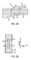
- FIG. 2A illustrates a schematic of a pump coupler with two pump fibers, wherein the pump coupler is located between two gain fibers in accordance with an embodiment of the present disclosure
- FIG. 2B illustrates a cross-sectional view of the pump coupler in accordance with an embodiment of the present disclosure
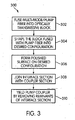
- FIG. 3 illustrates a method of manufacturing the pump coupler in accordance with an embodiment of the present disclosure
- FIGS. 4A-E illustrate procedures in the method of manufacturing the pump coupler in accordance with an embodiment of the present disclosure
- FIG. 5 illustrates a ray tracing analysis performed for a pump coupler having a single pump fiber, which is configured to couple pump radiation into the fiber section in accordance with an embodiment of the present disclosure
- FIG. 6 illustrates a ray tracing analysis performed for a pump coupler having four pump fibers that are configured to couple pump radiation into the fiber section in accordance with an embodiment of the present disclosure
- FIG. 7 illustrates an end view of a pump coupler having three pump fibers positioned in a pump coupler facet in accordance with an embodiment of the present disclosure
- FIG. 8A illustrates a top plan view of a pump coupler in accordance with an embodiment of the present disclosure
- FIG. 8B illustrates an edge view of a pump coupler in accordance with an embodiment of the present disclosure
- FIG. 8C illustrates an end view of a pump coupler in accordance with an embodiment of the present disclosure
- FIG. 9 illustrates a schematic of a pump coupler showing different angular dimensions in accordance with an embodiment of the present disclosure
- FIG. 10 illustrates a schematic of a pump coupler with pump fibers embedded into the pump coupler in accordance with an embodiment of the present disclosure
- a semi-guiding high-aspect ratio core (SHARC) fiber architecture that is scalable to high power levels is disclosed in related co-pending U.S. Patent Application No. 11/891,328, filed on August 9, 2007 and entitled "Method and Apparatus for Generation and Amplification of Light in a Semi-Guiding High Aspect Ratio Core Fiber".
- the cross-section of a SHARC fiber amplifier is schematically shown in FIG. 1 .
- Signal cladding layers are positioned in contact with the core to provide fast-axis waveguiding by means of total internal reflection.
- the material properties are designed to minimize any abrupt changes in the refractive index at the slow-axis edges of the core.
- the aspect ratio of the rectangular core may range from 30:1 to 100:1, or more depending on the desired power goal.
- the power scalability arises from the fact that the slow-axis dimension may be increased linearly with power such that the power is scaled accordingly. Hence, processes that limit the increase in power , such as optical damage and stimulated scattering, are held constant as the power is increased. Therefore, excellent beam quality may be achieved even at high powers using the SHARC fiber architecture.
- the SHARC fiber since the fast-axis dimension is maintained relatively small, the SHARC fiber may be coiled as easily as a conventional fiber.
- index-based guiding is employed in only one transverse direction (i.e., the fast-axis direction), and thus the term "semi-guiding." Higher-order planar fast-axis modes are stripped out of the core by coiling the fiber, analogous to the approach used with conventional large-mode area (LMA) fibers.
- LMA large-mode area
- the index-based guiding is not employed in the slow-axis direction mainly because it would lead to highly multimode operation. Instead an alternative form of spatial mode control is employed.
- the SHARC fiber When the SHARC fiber is employed as a laser oscillator, a single-mode performance in the slow-axis direction may be achieved using a low-Fresnel number resonator in that plane. Generally, this type of long and thin resonator is readily available, and is well known to produce diffraction-limited output beams.
- mode control When the SHARC fiber is employed as an amplifier, mode control may be achieved using a combination of mode-dependent gain and mode-dependent loss, such that the lowest-order mode has the greatest gain-loss difference.
- the present disclosure proposes a pump coupler configured to couple the outputs of multiple fiber-coupled semiconductor diode pump lasers into a gain fiber without any free-space optics (i.e., other than the micro-optics employed to couple diode laser beams, for example, into the pump fibers).
- This type of all-fiber capability avoids the use of complex free-space optics to shape the pump radiation and launch the pump radiation into the gain fiber.
- the free-space schemes typically require "fast" optics that are expensive and require precise alignment, and they must maintain that alignment precision over a wide range of operational thermal and vibrational environments.
- the pump coupler may be attached to a rectangular gain fiber.
- the pump radiation is configured to pass through the pump coupler into the gain fiber.
- the pump coupler may be spliced between two sections of gain fiber.
- the pump coupler of the present disclosure is designed such that it also propagates the signal from one gain fiber to the next.
- the pump coupler of the present disclosure is configured in one or more embodiments to couple pump radiation into a semi-guiding high aspect ratio core (SHARC) fiber.
- semi-guiding refers to the fact that the pump coupler provides index-based guiding in the narrow (fast-axis) direction, while free diffraction occurs in the wide (slow-axis) direction.
- the pump coupler of the present disclosure is designed such that it allows pump radiation to enter the gain fiber without imposing any appreciable loss on the signal beam, which also passes through the pump coupler.
- the pump radiation is configured to enter and propagate at an angle relative to the fiber axis, thus, allowing the pump radiation to efficiently enter the gain fiber from the edge of the fiber and propagate along the plane of the semi-guiding core.
- the semi-guiding core of the pump coupler also efficiently carries the signal from one end to the other.
- the signal-beam fast-axis dimension may only be in the range of 20 ⁇ m, the guiding in that direction is absolutely essential for efficient propagation of the beam from one gain fiber through the pump coupler into the next gain fiber.
- the slow-axis signal-beam dimension may be approximately around 1 mm or more. Since the length of the pump coupler length may approximately range from 5 to 10 mm, very little diffraction occurs in the wide direction (i.e., slow-axis signal-beam dimension), so no guiding is required by the pump coupler in the slow-axis signal-beam dimension.
- FIGS. 2A and 2B show a schematic of a pump coupler or optical fiber coupler 10 in accordance with an embodiment.
- Pump coupler 10 is configured for coupling pump radiation into rectangular optical fiber 12 (only a short section of which is illustrated).
- Pump coupler 10 includes fiber section 14 and pump fiber 16.
- Fiber section 14 includes semi-guiding core 18 having a high aspect ratio cross-section (i.e., the width of core 18 can exceed the thickness of core 18, for example, by a factor greater than 50) with a fast-axis dimension Y-Y and a slow-axis dimension X-X.
- Core 18 is positioned in contact with first and second signal claddings 20 and 22 to form reflective boundaries at fast-axis boundaries 24 and 26 of core 18.
- Pump fiber 16 is configured to couple the pump radiation into fiber section 14.
- Fiber section 14 includes joining or connecting portion or surface 28 that couples to rectangular fiber 12.
- the coordinate along the expanded dimension is traditionally referred to as the slow axis dimension X-X, while the narrow dimension is denoted the fast axis dimension Y-Y.
- the cross-sectional area of the expanded core is determined to maintain essentially constant amid safe power intensity level as the total beam power is increased.
- the damage-limited output power increases proportionally to the increase of the slow-axis core dimension X-X.
- pump coupler 10 is located between two gain or optical fibers 12.
- Fiber section 14 is configured to propagate the signal between the two gain or optical fibers 12 with minimal loss.
- the beam is guided through coupler 10 by the index-based waveguide.
- claddings 20 and 22 are positioned in contact with core 18 to provide fast-axis waveguiding by means of total internal reflection. As noted above, there is no guiding needed in the slow-axis direction X-X.
- gain fibers 12 and pump fibers 16 are made of a silica or a glass material. In another embodiment, gain fibers 12 and pump fibers 16 may be made of a polymer material, a plastic material, a fused silica material or other types of glass materials.
- a cross-section of pump fiber 16 is rectangular.
- the cross-sectional shape of pump fiber 16 may be selected from the group consisting of a square, an ellipse, a circle, a triangle, a polygon, or any other desired shaped.
- core 18 of fiber section 14 may include a passive SHARC fiber. In other words, core 18 of coupler or fiber section 14 includes a material without gain. In another embodiment, core 18 of fiber section 14 may include an active SHARC fiber. In other words, core 18 of coupler or fiber section 14 includes a material with gain. The use of an active SHARC fiber would provide amplification in power.
- joining or connecting surface or portion 28 of fiber section 14 of pump coupler 10 is coupled to rectangular fiber 12 by fusion bonding.
- coating 27 is provided on outer surface 29 of pump coupler 10.
- coating 27 is made from a polymer material, an acrylate material, or any other coating material appreciated by one skilled in the art.
- coating 27 is configured to protect the fiber from breaking.
- coating 27 is configured to control the range of angles internally reflected at surface 29.
- coating 27 is configured to control or determine a numerical aperture of the gain fiber at outer surface 29 of pump coupler 10, where the numerical aperture of the gain fiber is approximately 0.45 or more. In other words, coating 27 is configured to determine how high the angle of incidence of the light or radiation can be at outer surface 29.
- the numerical aperture is controlled or determined by changing the thickness of the coating, and/or material of the coating.
- FIG. 3 illustrates a method of manufacturing a pump coupler in accordance with an embodiment of the present disclosure.
- Method, 300 begins at procedure 302.
- procedure 302 as shown in FIG. 4A , multi-mode or pump fiber 16 (two are shown in the illustrated embodiment) capable of carrying the pump radiation is fused within optically transmissive block 30.
- optically transmissive block 30 may be made of a silica or glass material.
- the optically transmissive block 30 may be made of a polymer material, a plastic material or other types of glass materials.
- Method 300 then proceeds to procedure 304 in which block 30 that is fused with pump fiber 16 is shaped into a desired configuration 32.
- a dashed line "ABCD" is shown to indicate a fabrication pattern in block 30.
- Block 30 is cut into desired configuration 32 along the fabrication pattern ABCD.
- desired configuration 32 may be referred to as an interface section.
- Method 300 then proceeds to procedure 306 in which polished surface 34 is formed on desired configuration 32.
- FIG. 4C illustrates interface section 32 with pump fibers 16 and polished surface 34.
- Method 300 then proceeds to procedure 308 in which interface section 32 is coupled or joined with coupler or fiber section 14.
- coupler section 14 includes core 18 having a high aspect ratio cross-section with fast-axis dimension Y-Y and slow-axis dimension X-X.
- core 18 is positioned in contact with first and second signal claddings 20 and 22 to form the reflective boundaries at fast-axis boundaries 24 and 26 of core 18.
- joining interface section 32 to coupler section 14 includes bonding polished surface 34 of interface section 32 with surface 36 of coupler section 14.
- interface section 32 that includes pump fiber 16 is constructed and arranged to facilitate a strong, high-quality bond.
- polished surface 34 is made of sufficiently high quality so that it can be bonded to coupler section 14 as is shown in FIG. 4D .
- interface section 32 is joined to coupler section 14 using diffusion bonding.
- interface section 32 is joined to coupler section 14 using silicate bonding, fusion splicing, adhesive bonding, or any other attachment mechanism appreciated by one skilled in the art.
- Method 300 then proceeds to procedure 310 in which the remnants of interface section 32 are removed to yield a final single-sided coupler, as shown in FIG. 4E .
- pump fibers 16 are attached on only one side of fiber section or coupler section 14 forming a single-sided coupler configuration.
- Second pump fiber may be attached on an opposing side of fiber section 14 forming a double-sided coupler configuration as shown in FIG. 2A .
- a method similar to method 300 may be employed to produce the double-sided coupler as shown in FIG. 2A , with all of the bonding being done before the final shaping of interface sections 32. The use of more than two fibers is possible.
- fusing pump fiber 16 with optically transmissive block 30 includes penetrating pump fiber 16 all the way through desired configuration 32 to polished surface 34 of interface section 32.
- fusing pump fiber 16 with optically transmissive block 30 includes terminating pump fiber 16 at an intermediate section, wherein the intermediate section is positioned in between an entry section of the interface section and polished surface 34 of interface section 32.
- FIG. 5 illustrates a ray tracing analysis performed for the single-sided pump coupler 10 having single pump fiber 16 that is configured to couple pump radiation into fiber section 14 in accordance with an embodiment.
- Single pump fiber 16 may be configured to couple the pump radiation through the end of coupler 10.
- the cross-hatched area in the drawing represents the pump-radiation path within coupler 10.
- pump fiber 16 makes an angle ⁇ with coupler axis A-A.
- Edge surface 40 of interface section 32 makes an angle ⁇ with the coupler axis A-A.
- Angles ⁇ and ⁇ are design parameters for pump coupler 10 that can be optimized for best performance of pump coupler 10.
- FIG. 6 illustrates a ray tracing analysis performed for pump coupler 10 having four pump fibers 16 that are configured to couple pump radiation into fiber section 14 in accordance with an embodiment of the present disclosure.
- two pump fibers 16 couple or launch pump radiation (e.g., light) from each of the opposite edges of coupler 10.
- the fibers of the coupler shown in FIG. 6 are oriented parallel to the axis of the coupler A-A.
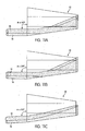
- the pump radiation may enter pump coupler 10 at an angle ⁇ , for example, as shown in FIGS. 11a-11c and 12 .
- FIG. 6 shows that the pump radiation from each pump fiber (two fibers 16A and 16B are shown in the illustrated embodiment) are reflected by the edge surface 40 such that the pump radiation passes through pump coupler end 50 into the adjoining gain fiber (not shown).
- the distance by which the pump fibers may penetrate into the pump coupler may depend on the angle at which the pump radiation enters the pump coupler. That is, for example, deeper penetrations of the pump fibers into the pump coupler are possible by increasing angle ⁇ as shown in FIG. 11A .
- the pump coupler in accordance with the embodiments of the present disclosure is compatible with two-dimensional arrays of pump fibers at the pump facets rather than just being a linear array, as shown in FIG. 6 .
- Calculations for a representative multi-kW-class SHARC fiber amplifier using 200 ⁇ m core, 0.22 numerical aperture pump fibers indicate that such a two-dimensional array of pump fibers is compatible with the dimensions and acceptance angles of the gain fiber.
- FIG. 7 shows a pump coupler used for such a fiber amplifier that allows pump facets having dimensions of 600 ⁇ m wide by 400 ⁇ m high.
- FIG. 7 illustrates how a two-dimensional array of three pump fibers 16 could be located in that area (i.e., having dimensions of 600 ⁇ m wide by 400 ⁇ m high).
- each pump fiber is configured to retain its own independent cladding.
- the pump fibers are partially fused together such that they share a common cladding, thus, allowing a higher pump-fiber packing density.
- the length of the pump coupler, not including the pump fibers is 5 mm.
- pump coupler 10 includes three pump fibers, where the pump fibers may have different sizes. For example, a larger diameter (i.e., 400 ⁇ m diameter) fiber may be used on the inner portion of the pump facet, and two smaller diameter (i.e., 200 ⁇ m diameter) fibers may be used on the outer portion of the pump facet. Two pump fibers 16, each having different diameters are used in pump coupler 10 shown in FIGS. 11A-11C . Therefore, in accordance with the embodiments of the present disclosure, any number of pump fibers may be used in the pump coupler. The number of pump fibers used in the pump coupler may be based on the pump power that needs to be coupled into the gain fibers. Also, each pump fiber used in the pump coupler may have different size.
- FIGS. 5, 6 , 8A-8C , 9; 10 , 11A-11C and 12 do not illustrate gain fibers 12 (as shown in FIG. 2A ) positioned on ends or edges of pump coupler 10 for clarity. However, in practice, gain fiber 12 would be positioned on each edge of the pump coupler.
Landscapes
- Physics & Mathematics (AREA)
- General Physics & Mathematics (AREA)
- Optics & Photonics (AREA)
- Lasers (AREA)
- Optical Couplings Of Light Guides (AREA)
Claims (15)
- Coupleur (10) à fibre optique, pour le couplage d'un rayonnement de pompe multi-mode dans une fibre optique (12), caractérisé en ce qu'il comprend :- une section de fibre (14) comprenant un coeur (18) présentant une section transversale ayant un rapport de dimensions élevé, avec une dimension d'axe rapide (Y-Y) étroite et une dimension d'axe lent (X-X) plus large, et une section d'interface (32), dans lequel le coeur est placé en contact avec des premier et deuxième gaines de signal (20, 22) pour former des frontières réfléchissantes seulement aux frontières d'axe rapide (24, 26) du coeur ; et- une fibre de pompe (16), couplée à la section de fibre via la section d'interface et configurée pour coupler le rayonnement de pompe dans la section de fibre, de manière à ce que le rayonnement de pompe pénètre au moins dans la dimension étroite.
- Coupleur selon la revendication 1, caractérisé en ce qu'une section transversale de la fibre de pompe (16) est de forme rectangulaire ou carrée.
- Coupleur selon la revendication 1, caractérisé en ce que la fibre de pompe (16) est attachée sur une face de la section de fibre formant une configuration de coupleur à une seule face.
- Coupleur selon la revendication 3, caractérisé en ce qu'une deuxième fibre de pompe (16) est attachée sur une face opposée de la section de fibre (14) formant une configuration de coupleur à deux faces.
- Coupleur selon la revendication 1, caractérisé en ce que le coeur (18) de la section de fibre (14) comprend un matériau ayant un gain associé.
- Coupleur selon la revendication 1, caractérisé en ce qu'il comprend une pluralité de fibres de pompe (16), configurées pour coupler le rayonnement de pompe dans la section de fibre (14), depuis des faces opposées du coupleur.
- Coupleur selon la revendication 1, caractérisé en ce que le rayonnement de pompe est configuré pour pénétrer dans le coupleur sous un angle (θ) par rapport à un axe central (A-A) du coupleur.
- Coupleur selon la revendication 1, comprenant en outre un revêtement (27) en polymère, prévu sur une surface extérieure (29) de la section de fibre (14) et de la fibre de pompe (16).
- Procédé de fabrication d'un coupleur de pompe (10), caractérisé en ce qu'il comprend :- fourniture d'une section d'interface (32) comprenant au moins une fibre de pompe (16) configurée pour coupler un rayonnement de pompe multi-mode dans une section de coupleur (14) ; et- jonction de la section d'interface à la section de coupleur, dans lequel la section de coupleur comprend un coeur (18) présentant une section transversale ayant un rapport de dimensions élevé, avec une dimension d'axe rapide (Y-Y) étroite et une dimension d'axe lent (X-X) plus large, le coeur étant placé en contact avec des premier et deuxième gaines de signal (20, 22) pour former des frontières réfléchissantes seulement aux frontières daxe rapide (24, 26) du coeur ; et le rayonnement de pompe pénètre au moins dans la dimension étroite.
- Procédé selon la revendication 9, caractérisé en ce que la fourniture de la section d'interface (32) comprend :(a) la fusion de la au moins une fibre de pompe (16) avec un bloc (30) optiquement transmissif ;(b) le façonnage à une configuration souhaitée du bloc optiquement transmissif fondu avec la au moins une fibre de pompe ; et(c) le formage d'une surface (34) polie sur la section d'interface.
- Procédé selon la revendication 9, caractérisé en ce que la jonction de la section d'interface (32) à la section de coupleur (14) comprend la liaison d'une surface (34) polie de la section d'interface à une surface (36) de la section de coupleur.
- Procédé selon la revendication 10, caractérisé en ce que la fusion de la au moins une fibre de pompe (16) avec le bloc (30) optiquement transmissif comprend la pénétration d'une ou plusieurs de la au moins une fibre de pompe (16) tout au long d'elle, sous la configuration souhaitée, jusqu'à la surface (34) polie de la section d'interface (32).
- Procédé selon la revendication 10, caractérisé en ce que la fusion de la au moins une fibre de pompe (16) avec le bloc (30) optiquement transmissif comprend la terminaison d'une ou plusieurs de la au moins une fibre de pompe (16) en une section intermédiaire, dans lequel la section intermédiaire est placée entre une section d'entrée et la surface (34) polie de la section d'interface.
- Procédé selon la revendication 9, caractérisé en ce qu'il comprend en outre la fourniture de la section de coupleur (14) comprenant un matériau ayant un gain associé.
- Procédé selon la revendication 9, caractérisé en ce qu'il comprend en outre la commande d'une ouverture numérique de la fibre, par fourniture d'un revêtement (27) sur une surface extérieure (29) de la section d'interface (32) et de la section de coupleur (14).
Applications Claiming Priority (1)
| Application Number | Priority Date | Filing Date | Title |
|---|---|---|---|
| US12/357,540 US7978943B2 (en) | 2009-01-22 | 2009-01-22 | Monolithic pump coupler for high-aspect ratio solid-state gain media |
Publications (2)
| Publication Number | Publication Date |
|---|---|
| EP2211216A1 EP2211216A1 (fr) | 2010-07-28 |
| EP2211216B1 true EP2211216B1 (fr) | 2012-06-27 |
Family
ID=41722744
Family Applications (1)
| Application Number | Title | Priority Date | Filing Date |
|---|---|---|---|
| EP10151169A Active EP2211216B1 (fr) | 2009-01-22 | 2010-01-20 | Coupleur de pompe monolytique pour guide optique amplificateur avec rapport largeur/hauteur élevé |
Country Status (2)
| Country | Link |
|---|---|
| US (1) | US7978943B2 (fr) |
| EP (1) | EP2211216B1 (fr) |
Families Citing this family (7)
| Publication number | Priority date | Publication date | Assignee | Title |
|---|---|---|---|---|
| US7991253B2 (en) * | 2009-04-30 | 2011-08-02 | Hewlett-Packard Development Company, L.P. | Memristive array with waveguide |
| JP5933561B2 (ja) * | 2010-09-21 | 2016-06-15 | オーエフエス ファイテル,エルエルシー | ファイバ光カプラのna低減 |
| CA2863024A1 (fr) * | 2011-02-03 | 2013-08-09 | 3Sae Technologies, Inc. | Fibre a pompage lateral, son procede de fabrication et dispositifs optiques l'utilisant |
| JP6126562B2 (ja) * | 2014-08-27 | 2017-05-10 | 三星ダイヤモンド工業株式会社 | 光ファイバ装置 |
| US10177521B2 (en) | 2017-02-20 | 2019-01-08 | Raytheon Company | Optical fiber for light amplification having a core with low bend loss and end features with high bend loss and related method |
| US10222623B2 (en) | 2017-04-26 | 2019-03-05 | Raytheon Company | Composite graded-index fiber mode field adaptor for high-aspect-ratio core optical fibers |
| US11280973B2 (en) | 2020-06-01 | 2022-03-22 | Raytheon Company | Compact package for high-aspect-ratio rectangular (HARR) optical fiber or other optical fiber |
Citations (1)
| Publication number | Priority date | Publication date | Assignee | Title |
|---|---|---|---|---|
| US20030031226A1 (en) * | 2001-05-22 | 2003-02-13 | Byren Robert W. | System and method for pumping a slab laser |
Family Cites Families (29)
| Publication number | Priority date | Publication date | Assignee | Title |
|---|---|---|---|---|
| DE2614647A1 (de) | 1976-04-05 | 1977-10-13 | Siemens Ag | Aus-/einkoppler fuer multimode-lichtleitfasern |
| US4553238A (en) | 1983-09-30 | 1985-11-12 | The Board Of Trustees Of The Leland Stanford University | Fiber optic amplifier |
| US4848881A (en) | 1984-12-03 | 1989-07-18 | Hughes Aircraft Company | Variable lens and birefringence compensator |
| US4818062A (en) | 1987-04-28 | 1989-04-04 | Spectra Diode Laboratories, Inc. | Optical system with bright light output |
| US4815079A (en) | 1987-12-17 | 1989-03-21 | Polaroid Corporation | Optical fiber lasers and amplifiers |
| US5046809A (en) | 1989-09-29 | 1991-09-10 | Siemens Aktiengesellschaft | Coupling arrangement for optically coupling a fiber to a planar optical waveguide integrated on a substrate |
| US5555254A (en) | 1993-11-05 | 1996-09-10 | Trw Inc. | High brightness solid-state laser with zig-zag amplifier |
| US5386427A (en) | 1994-02-10 | 1995-01-31 | Massachusetts Institute Of Technology | Thermally controlled lenses for lasers |
| US5909529A (en) | 1996-10-10 | 1999-06-01 | Corning Incorporated | Method of manufacturing planar gradient-index waveguide lenses |
| US6477295B1 (en) | 1997-01-16 | 2002-11-05 | Jds Uniphase Corporation | Pump coupling of double clad fibers |
| US7164818B2 (en) | 2001-05-03 | 2007-01-16 | Neophontonics Corporation | Integrated gradient index lenses |
| US5864644A (en) | 1997-07-21 | 1999-01-26 | Lucent Technologies Inc. | Tapered fiber bundles for coupling light into and out of cladding-pumped fiber devices |
| US5930433A (en) | 1997-07-23 | 1999-07-27 | Hewlett-Packard Company | Waveguide array document scanner |
| US6014391A (en) | 1997-12-19 | 2000-01-11 | Raytheon Company | Thermally improved slab laser pump cavity apparatus with integral concentrator and method of making same |
| EP1155258A1 (fr) | 1998-12-30 | 2001-11-21 | Oseir Oy | Procede et dispositif de couplage de sources de lumiere a un guide lumineux |
| US6317548B1 (en) | 1999-03-11 | 2001-11-13 | Hughes Electronics Corporation | Temperature and optical length control of optical fibers and optical waveguide devices |
| US6370297B1 (en) * | 1999-03-31 | 2002-04-09 | Massachusetts Institute Of Technology | Side pumped optical amplifiers and lasers |
| US6229939B1 (en) | 1999-06-03 | 2001-05-08 | Trw Inc. | High power fiber ribbon laser and amplifier |
| US6400871B1 (en) | 2000-05-19 | 2002-06-04 | Hrl Laboratories, Llc | Phase control mechanism for coherent fiber amplifier arrays |
| EP1168532A1 (fr) | 2000-06-23 | 2002-01-02 | Universität Bern | Méthode de compensation des effets thermo-optiques |
| US6594420B1 (en) | 2000-07-28 | 2003-07-15 | Harris Corporation | Multi-fiber ribbon form factor-compliant, integrated multi-channel optical amplifier |
| US6594410B2 (en) * | 2000-08-26 | 2003-07-15 | Cidra Corporation | Wide range tunable optical filter |
| GB0031463D0 (en) | 2000-12-21 | 2001-02-07 | Univ Southampton | Fibre laser |
| SE0004839D0 (sv) * | 2000-12-22 | 2000-12-22 | Ericsson Telefon Ab L M | Method and communication apparatus in a communication system |
| US6529318B1 (en) | 2001-08-30 | 2003-03-04 | Np Photonics, Inc. | Total internal reflection (TIR) coupler and method for side-coupling pump light into a fiber |
| US6904219B1 (en) * | 2002-07-26 | 2005-06-07 | Boston Laser, Inc. | Ultra high-power continuous wave planar waveguide amplifiers and lasers |
| DE602004014766D1 (de) * | 2003-06-16 | 2008-08-14 | Soreq Nuclear Res Ct | Optische vorrichtung |
| US7539377B2 (en) * | 2007-01-11 | 2009-05-26 | Gonthier Francois | Method and device for optically coupling optical fibres |
| US7983312B2 (en) | 2007-08-09 | 2011-07-19 | Raytheon Company | Method and apparatus for generation and amplification of light in a semi-guiding high aspect ratio core fiber |
-
2009
- 2009-01-22 US US12/357,540 patent/US7978943B2/en active Active
-
2010
- 2010-01-20 EP EP10151169A patent/EP2211216B1/fr active Active
Patent Citations (1)
| Publication number | Priority date | Publication date | Assignee | Title |
|---|---|---|---|---|
| US20030031226A1 (en) * | 2001-05-22 | 2003-02-13 | Byren Robert W. | System and method for pumping a slab laser |
Also Published As
| Publication number | Publication date |
|---|---|
| US20100183260A1 (en) | 2010-07-22 |
| EP2211216A1 (fr) | 2010-07-28 |
| US7978943B2 (en) | 2011-07-12 |
Similar Documents
| Publication | Publication Date | Title |
|---|---|---|
| EP2028734B1 (fr) | Appareil pour fournir un rayonnement optique | |
| US6704479B2 (en) | Method for coupling light into cladding-pumped fiber sources using an embedded mirror | |
| US7957432B2 (en) | Light coupler and fiber laser system including the same | |
| EP2841983B1 (fr) | Coupleur de fibres optiques pour coupler des faisceaux de signal en un faisceau optique de forme non circulaire | |
| US6990278B2 (en) | Mode multiplexing optical coupling device | |
| US8837885B2 (en) | Optic coupler, optical fiber laser device, and active optical module using the same | |
| EP2211216A1 (fr) | Coupleur de pompe monolytique pour guide optique amplificateur avec rapport largeur/hauteur élevé | |
| US9494739B2 (en) | Cladding mode spatial filter | |
| JP2007249213A (ja) | 光ファイバを側面ポンピングする方法とその装置 | |
| US20110069725A1 (en) | Method and apparatus for generation and amplification of light in a semi-guiding high aspect ratio core fiber | |
| CA2613137A1 (fr) | Dispositifs de couplage optique, procedes de production et utilisation de ces dispositifs | |
| US8588267B1 (en) | Rectangular core optical fiber and rectangular core optical fiber arrays | |
| US6882664B2 (en) | Laser with internally coupled pump source | |
| US7983313B2 (en) | System and method for coupling multiple beams to an active fiber | |
| US11808982B2 (en) | Optical combiner, laser device, and method for manufacturing optical combiner | |
| US6766075B1 (en) | Side pumping of optical fiber systems via multiple delivery fibers | |
| EP2671106B1 (fr) | Fibre à pompage latéral, son procédé de fabrication et dispositifs optiques l'utilisant | |
| CN115808804A (zh) | 一种激光光斑整形器件及其制作方法 | |
| JP3939816B2 (ja) | レーザ装置 | |
| WO2004083921A1 (fr) | Fibre optique et procede de lancement de la puissance de pompage dans une fibre et son procede de fabrication | |
| WO2010149163A1 (fr) | Dispositif de coupleur optique | |
| KR101544455B1 (ko) | 광섬유 펌프-시그널 결합기 및 이의 제조방법 | |
| WO2020264126A1 (fr) | Amplificateur à fibre à pompage inverse avec suppresseur de lumière de gaine entre segments de fibre active | |
| JP2000150987A (ja) | 光ファイバレーザとレーザ装置および光ファイバアンプ | |
| US20040047553A1 (en) | Injection device for optical fibre and preparation method |
Legal Events
| Date | Code | Title | Description |
|---|---|---|---|
| PUAI | Public reference made under article 153(3) epc to a published international application that has entered the european phase |
Free format text: ORIGINAL CODE: 0009012 |
|
| AK | Designated contracting states |
Kind code of ref document: A1 Designated state(s): AT BE BG CH CY CZ DE DK EE ES FI FR GB GR HR HU IE IS IT LI LT LU LV MC MK MT NL NO PL PT RO SE SI SK SM TR |
|
| 17P | Request for examination filed |
Effective date: 20110124 |
|
| GRAP | Despatch of communication of intention to grant a patent |
Free format text: ORIGINAL CODE: EPIDOSNIGR1 |
|
| GRAS | Grant fee paid |
Free format text: ORIGINAL CODE: EPIDOSNIGR3 |
|
| GRAA | (expected) grant |
Free format text: ORIGINAL CODE: 0009210 |
|
| AK | Designated contracting states |
Kind code of ref document: B1 Designated state(s): AT BE BG CH CY CZ DE DK EE ES FI FR GB GR HR HU IE IS IT LI LT LU LV MC MK MT NL NO PL PT RO SE SI SK SM TR |
|
| REG | Reference to a national code |
Ref country code: GB Ref legal event code: FG4D |
|
| REG | Reference to a national code |
Ref country code: CH Ref legal event code: EP |
|
| REG | Reference to a national code |
Ref country code: AT Ref legal event code: REF Ref document number: 564511 Country of ref document: AT Kind code of ref document: T Effective date: 20120715 |
|
| REG | Reference to a national code |
Ref country code: IE Ref legal event code: FG4D |
|
| REG | Reference to a national code |
Ref country code: DE Ref legal event code: R096 Ref document number: 602010001997 Country of ref document: DE Effective date: 20120823 |
|
| PG25 | Lapsed in a contracting state [announced via postgrant information from national office to epo] |
Ref country code: FI Free format text: LAPSE BECAUSE OF FAILURE TO SUBMIT A TRANSLATION OF THE DESCRIPTION OR TO PAY THE FEE WITHIN THE PRESCRIBED TIME-LIMIT Effective date: 20120627 Ref country code: LT Free format text: LAPSE BECAUSE OF FAILURE TO SUBMIT A TRANSLATION OF THE DESCRIPTION OR TO PAY THE FEE WITHIN THE PRESCRIBED TIME-LIMIT Effective date: 20120627 Ref country code: SE Free format text: LAPSE BECAUSE OF FAILURE TO SUBMIT A TRANSLATION OF THE DESCRIPTION OR TO PAY THE FEE WITHIN THE PRESCRIBED TIME-LIMIT Effective date: 20120627 Ref country code: NO Free format text: LAPSE BECAUSE OF FAILURE TO SUBMIT A TRANSLATION OF THE DESCRIPTION OR TO PAY THE FEE WITHIN THE PRESCRIBED TIME-LIMIT Effective date: 20120927 |
|
| REG | Reference to a national code |
Ref country code: NL Ref legal event code: VDEP Effective date: 20120627 |
|
| REG | Reference to a national code |
Ref country code: AT Ref legal event code: MK05 Ref document number: 564511 Country of ref document: AT Kind code of ref document: T Effective date: 20120627 |
|
| REG | Reference to a national code |
Ref country code: LT Ref legal event code: MG4D Effective date: 20120627 |
|
| PG25 | Lapsed in a contracting state [announced via postgrant information from national office to epo] |
Ref country code: SI Free format text: LAPSE BECAUSE OF FAILURE TO SUBMIT A TRANSLATION OF THE DESCRIPTION OR TO PAY THE FEE WITHIN THE PRESCRIBED TIME-LIMIT Effective date: 20120627 Ref country code: GR Free format text: LAPSE BECAUSE OF FAILURE TO SUBMIT A TRANSLATION OF THE DESCRIPTION OR TO PAY THE FEE WITHIN THE PRESCRIBED TIME-LIMIT Effective date: 20120928 Ref country code: LV Free format text: LAPSE BECAUSE OF FAILURE TO SUBMIT A TRANSLATION OF THE DESCRIPTION OR TO PAY THE FEE WITHIN THE PRESCRIBED TIME-LIMIT Effective date: 20120627 Ref country code: HR Free format text: LAPSE BECAUSE OF FAILURE TO SUBMIT A TRANSLATION OF THE DESCRIPTION OR TO PAY THE FEE WITHIN THE PRESCRIBED TIME-LIMIT Effective date: 20120627 |
|
| PG25 | Lapsed in a contracting state [announced via postgrant information from national office to epo] |
Ref country code: BE Free format text: LAPSE BECAUSE OF FAILURE TO SUBMIT A TRANSLATION OF THE DESCRIPTION OR TO PAY THE FEE WITHIN THE PRESCRIBED TIME-LIMIT Effective date: 20120627 Ref country code: CZ Free format text: LAPSE BECAUSE OF FAILURE TO SUBMIT A TRANSLATION OF THE DESCRIPTION OR TO PAY THE FEE WITHIN THE PRESCRIBED TIME-LIMIT Effective date: 20120627 Ref country code: SK Free format text: LAPSE BECAUSE OF FAILURE TO SUBMIT A TRANSLATION OF THE DESCRIPTION OR TO PAY THE FEE WITHIN THE PRESCRIBED TIME-LIMIT Effective date: 20120627 Ref country code: CY Free format text: LAPSE BECAUSE OF FAILURE TO SUBMIT A TRANSLATION OF THE DESCRIPTION OR TO PAY THE FEE WITHIN THE PRESCRIBED TIME-LIMIT Effective date: 20120627 Ref country code: IS Free format text: LAPSE BECAUSE OF FAILURE TO SUBMIT A TRANSLATION OF THE DESCRIPTION OR TO PAY THE FEE WITHIN THE PRESCRIBED TIME-LIMIT Effective date: 20121027 Ref country code: EE Free format text: LAPSE BECAUSE OF FAILURE TO SUBMIT A TRANSLATION OF THE DESCRIPTION OR TO PAY THE FEE WITHIN THE PRESCRIBED TIME-LIMIT Effective date: 20120627 Ref country code: AT Free format text: LAPSE BECAUSE OF FAILURE TO SUBMIT A TRANSLATION OF THE DESCRIPTION OR TO PAY THE FEE WITHIN THE PRESCRIBED TIME-LIMIT Effective date: 20120627 Ref country code: RO Free format text: LAPSE BECAUSE OF FAILURE TO SUBMIT A TRANSLATION OF THE DESCRIPTION OR TO PAY THE FEE WITHIN THE PRESCRIBED TIME-LIMIT Effective date: 20120627 |
|
| PG25 | Lapsed in a contracting state [announced via postgrant information from national office to epo] |
Ref country code: IT Free format text: LAPSE BECAUSE OF FAILURE TO SUBMIT A TRANSLATION OF THE DESCRIPTION OR TO PAY THE FEE WITHIN THE PRESCRIBED TIME-LIMIT Effective date: 20120627 Ref country code: PT Free format text: LAPSE BECAUSE OF FAILURE TO SUBMIT A TRANSLATION OF THE DESCRIPTION OR TO PAY THE FEE WITHIN THE PRESCRIBED TIME-LIMIT Effective date: 20121029 Ref country code: PL Free format text: LAPSE BECAUSE OF FAILURE TO SUBMIT A TRANSLATION OF THE DESCRIPTION OR TO PAY THE FEE WITHIN THE PRESCRIBED TIME-LIMIT Effective date: 20120627 |
|
| PG25 | Lapsed in a contracting state [announced via postgrant information from national office to epo] |
Ref country code: NL Free format text: LAPSE BECAUSE OF FAILURE TO SUBMIT A TRANSLATION OF THE DESCRIPTION OR TO PAY THE FEE WITHIN THE PRESCRIBED TIME-LIMIT Effective date: 20120627 |
|
| PG25 | Lapsed in a contracting state [announced via postgrant information from national office to epo] |
Ref country code: ES Free format text: LAPSE BECAUSE OF FAILURE TO SUBMIT A TRANSLATION OF THE DESCRIPTION OR TO PAY THE FEE WITHIN THE PRESCRIBED TIME-LIMIT Effective date: 20121008 Ref country code: DK Free format text: LAPSE BECAUSE OF FAILURE TO SUBMIT A TRANSLATION OF THE DESCRIPTION OR TO PAY THE FEE WITHIN THE PRESCRIBED TIME-LIMIT Effective date: 20120627 |
|
| PLBE | No opposition filed within time limit |
Free format text: ORIGINAL CODE: 0009261 |
|
| STAA | Information on the status of an ep patent application or granted ep patent |
Free format text: STATUS: NO OPPOSITION FILED WITHIN TIME LIMIT |
|
| 26N | No opposition filed |
Effective date: 20130328 |
|
| REG | Reference to a national code |
Ref country code: DE Ref legal event code: R097 Ref document number: 602010001997 Country of ref document: DE Effective date: 20130328 |
|
| PG25 | Lapsed in a contracting state [announced via postgrant information from national office to epo] |
Ref country code: BG Free format text: LAPSE BECAUSE OF FAILURE TO SUBMIT A TRANSLATION OF THE DESCRIPTION OR TO PAY THE FEE WITHIN THE PRESCRIBED TIME-LIMIT Effective date: 20120927 |
|
| PG25 | Lapsed in a contracting state [announced via postgrant information from national office to epo] |
Ref country code: MC Free format text: LAPSE BECAUSE OF NON-PAYMENT OF DUE FEES Effective date: 20130131 |
|
| REG | Reference to a national code |
Ref country code: IE Ref legal event code: MM4A |
|
| PG25 | Lapsed in a contracting state [announced via postgrant information from national office to epo] |
Ref country code: IE Free format text: LAPSE BECAUSE OF NON-PAYMENT OF DUE FEES Effective date: 20130120 |
|
| PG25 | Lapsed in a contracting state [announced via postgrant information from national office to epo] |
Ref country code: MT Free format text: LAPSE BECAUSE OF FAILURE TO SUBMIT A TRANSLATION OF THE DESCRIPTION OR TO PAY THE FEE WITHIN THE PRESCRIBED TIME-LIMIT Effective date: 20120627 |
|
| REG | Reference to a national code |
Ref country code: CH Ref legal event code: PL |
|
| PG25 | Lapsed in a contracting state [announced via postgrant information from national office to epo] |
Ref country code: LI Free format text: LAPSE BECAUSE OF NON-PAYMENT OF DUE FEES Effective date: 20140131 Ref country code: CH Free format text: LAPSE BECAUSE OF NON-PAYMENT OF DUE FEES Effective date: 20140131 |
|
| PG25 | Lapsed in a contracting state [announced via postgrant information from national office to epo] |
Ref country code: SM Free format text: LAPSE BECAUSE OF FAILURE TO SUBMIT A TRANSLATION OF THE DESCRIPTION OR TO PAY THE FEE WITHIN THE PRESCRIBED TIME-LIMIT Effective date: 20120627 |
|
| PG25 | Lapsed in a contracting state [announced via postgrant information from national office to epo] |
Ref country code: TR Free format text: LAPSE BECAUSE OF FAILURE TO SUBMIT A TRANSLATION OF THE DESCRIPTION OR TO PAY THE FEE WITHIN THE PRESCRIBED TIME-LIMIT Effective date: 20120627 |
|
| PG25 | Lapsed in a contracting state [announced via postgrant information from national office to epo] |
Ref country code: HU Free format text: LAPSE BECAUSE OF FAILURE TO SUBMIT A TRANSLATION OF THE DESCRIPTION OR TO PAY THE FEE WITHIN THE PRESCRIBED TIME-LIMIT; INVALID AB INITIO Effective date: 20100120 Ref country code: MK Free format text: LAPSE BECAUSE OF FAILURE TO SUBMIT A TRANSLATION OF THE DESCRIPTION OR TO PAY THE FEE WITHIN THE PRESCRIBED TIME-LIMIT Effective date: 20120627 Ref country code: LU Free format text: LAPSE BECAUSE OF NON-PAYMENT OF DUE FEES Effective date: 20130120 |
|
| REG | Reference to a national code |
Ref country code: FR Ref legal event code: PLFP Year of fee payment: 7 |
|
| REG | Reference to a national code |
Ref country code: FR Ref legal event code: PLFP Year of fee payment: 8 |
|
| REG | Reference to a national code |
Ref country code: FR Ref legal event code: PLFP Year of fee payment: 9 |
|
| P01 | Opt-out of the competence of the unified patent court (upc) registered |
Effective date: 20230530 |
|
| PGFP | Annual fee paid to national office [announced via postgrant information from national office to epo] |
Ref country code: GB Payment date: 20251220 Year of fee payment: 17 |
|
| PGFP | Annual fee paid to national office [announced via postgrant information from national office to epo] |
Ref country code: FR Payment date: 20251217 Year of fee payment: 17 |
|
| PGFP | Annual fee paid to national office [announced via postgrant information from national office to epo] |
Ref country code: DE Payment date: 20251217 Year of fee payment: 17 |