EP2212036B1 - Procédé de nettoyage - Google Patents
Procédé de nettoyage Download PDFInfo
- Publication number
- EP2212036B1 EP2212036B1 EP08852747.8A EP08852747A EP2212036B1 EP 2212036 B1 EP2212036 B1 EP 2212036B1 EP 08852747 A EP08852747 A EP 08852747A EP 2212036 B1 EP2212036 B1 EP 2212036B1
- Authority
- EP
- European Patent Office
- Prior art keywords
- burner
- cleaning
- pressure vessel
- compressed air
- cleaning device
- Prior art date
- Legal status (The legal status is an assumption and is not a legal conclusion. Google has not performed a legal analysis and makes no representation as to the accuracy of the status listed.)
- Not-in-force
Links
- 238000004140 cleaning Methods 0.000 title claims description 59
- 238000000034 method Methods 0.000 title claims description 21
- 239000000446 fuel Substances 0.000 claims description 26
- 238000002485 combustion reaction Methods 0.000 claims description 19
- 239000002245 particle Substances 0.000 claims description 17
- 239000012530 fluid Substances 0.000 claims description 4
- 238000005406 washing Methods 0.000 claims 2
- 239000007788 liquid Substances 0.000 description 32
- 239000007789 gas Substances 0.000 description 23
- 238000007664 blowing Methods 0.000 description 5
- 238000009792 diffusion process Methods 0.000 description 5
- 230000000694 effects Effects 0.000 description 5
- 238000011010 flushing procedure Methods 0.000 description 4
- 239000012535 impurity Substances 0.000 description 4
- 239000000463 material Substances 0.000 description 4
- KRKNYBCHXYNGOX-UHFFFAOYSA-N citric acid Chemical compound OC(=O)CC(O)(C(O)=O)CC(O)=O KRKNYBCHXYNGOX-UHFFFAOYSA-N 0.000 description 3
- 238000004891 communication Methods 0.000 description 3
- MBMLMWLHJBBADN-UHFFFAOYSA-N Ferrous sulfide Chemical compound [Fe]=S MBMLMWLHJBBADN-UHFFFAOYSA-N 0.000 description 2
- 229910000831 Steel Inorganic materials 0.000 description 2
- 238000006243 chemical reaction Methods 0.000 description 2
- 239000000567 combustion gas Substances 0.000 description 2
- 238000011109 contamination Methods 0.000 description 2
- 238000000151 deposition Methods 0.000 description 2
- 238000011049 filling Methods 0.000 description 2
- 230000001771 impaired effect Effects 0.000 description 2
- 238000002156 mixing Methods 0.000 description 2
- 238000000746 purification Methods 0.000 description 2
- 239000010959 steel Substances 0.000 description 2
- 150000003464 sulfur compounds Chemical class 0.000 description 2
- 229910000838 Al alloy Inorganic materials 0.000 description 1
- 229910000851 Alloy steel Inorganic materials 0.000 description 1
- 241001156002 Anthonomus pomorum Species 0.000 description 1
- 239000002253 acid Substances 0.000 description 1
- 230000002411 adverse Effects 0.000 description 1
- XAGFODPZIPBFFR-UHFFFAOYSA-N aluminium Chemical compound [Al] XAGFODPZIPBFFR-UHFFFAOYSA-N 0.000 description 1
- 229910052782 aluminium Inorganic materials 0.000 description 1
- 239000012459 cleaning agent Substances 0.000 description 1
- 238000005260 corrosion Methods 0.000 description 1
- 230000007797 corrosion Effects 0.000 description 1
- 230000008021 deposition Effects 0.000 description 1
- 238000004090 dissolution Methods 0.000 description 1
- 238000001035 drying Methods 0.000 description 1
- 230000008030 elimination Effects 0.000 description 1
- 238000003379 elimination reaction Methods 0.000 description 1
- 230000002349 favourable effect Effects 0.000 description 1
- 238000010304 firing Methods 0.000 description 1
- 238000002347 injection Methods 0.000 description 1
- 239000007924 injection Substances 0.000 description 1
- 230000001404 mediated effect Effects 0.000 description 1
- 239000000203 mixture Substances 0.000 description 1
- 150000007524 organic acids Chemical class 0.000 description 1
- 235000005985 organic acids Nutrition 0.000 description 1
- 239000000843 powder Substances 0.000 description 1
- 239000013049 sediment Substances 0.000 description 1
- 239000000243 solution Substances 0.000 description 1
- 239000000126 substance Substances 0.000 description 1
- 238000011144 upstream manufacturing Methods 0.000 description 1
- XLYOFNOQVPJJNP-UHFFFAOYSA-N water Substances O XLYOFNOQVPJJNP-UHFFFAOYSA-N 0.000 description 1
Images

Classifications
-
- B—PERFORMING OPERATIONS; TRANSPORTING
- B08—CLEANING
- B08B—CLEANING IN GENERAL; PREVENTION OF FOULING IN GENERAL
- B08B3/00—Cleaning by methods involving the use or presence of liquid or steam
- B08B3/04—Cleaning involving contact with liquid
-
- B—PERFORMING OPERATIONS; TRANSPORTING
- B08—CLEANING
- B08B—CLEANING IN GENERAL; PREVENTION OF FOULING IN GENERAL
- B08B9/00—Cleaning hollow articles by methods or apparatus specially adapted thereto
-
- B—PERFORMING OPERATIONS; TRANSPORTING
- B08—CLEANING
- B08B—CLEANING IN GENERAL; PREVENTION OF FOULING IN GENERAL
- B08B9/00—Cleaning hollow articles by methods or apparatus specially adapted thereto
- B08B9/02—Cleaning pipes or tubes or systems of pipes or tubes
- B08B9/027—Cleaning the internal surfaces; Removal of blockages
-
- C—CHEMISTRY; METALLURGY
- C11—ANIMAL OR VEGETABLE OILS, FATS, FATTY SUBSTANCES OR WAXES; FATTY ACIDS THEREFROM; DETERGENTS; CANDLES
- C11D—DETERGENT COMPOSITIONS; USE OF SINGLE SUBSTANCES AS DETERGENTS; SOAP OR SOAP-MAKING; RESIN SOAPS; RECOVERY OF GLYCEROL
- C11D7/00—Compositions of detergents based essentially on non-surface-active compounds
- C11D7/22—Organic compounds
- C11D7/26—Organic compounds containing oxygen
- C11D7/265—Carboxylic acids or salts thereof
-
- C—CHEMISTRY; METALLURGY
- C11—ANIMAL OR VEGETABLE OILS, FATS, FATTY SUBSTANCES OR WAXES; FATTY ACIDS THEREFROM; DETERGENTS; CANDLES
- C11D—DETERGENT COMPOSITIONS; USE OF SINGLE SUBSTANCES AS DETERGENTS; SOAP OR SOAP-MAKING; RESIN SOAPS; RECOVERY OF GLYCEROL
- C11D2111/00—Cleaning compositions characterised by the objects to be cleaned; Cleaning compositions characterised by non-standard cleaning or washing processes
- C11D2111/10—Objects to be cleaned
- C11D2111/14—Hard surfaces
- C11D2111/20—Industrial or commercial equipment, e.g. reactors, tubes or engines
-
- C—CHEMISTRY; METALLURGY
- C11—ANIMAL OR VEGETABLE OILS, FATS, FATTY SUBSTANCES OR WAXES; FATTY ACIDS THEREFROM; DETERGENTS; CANDLES
- C11D—DETERGENT COMPOSITIONS; USE OF SINGLE SUBSTANCES AS DETERGENTS; SOAP OR SOAP-MAKING; RESIN SOAPS; RECOVERY OF GLYCEROL
- C11D2111/00—Cleaning compositions characterised by the objects to be cleaned; Cleaning compositions characterised by non-standard cleaning or washing processes
- C11D2111/40—Specific cleaning or washing processes
- C11D2111/46—Specific cleaning or washing processes applying energy, e.g. irradiation
Definitions
- the present invention relates to a method for cleaning components of a burner.
- Gas turbine combustors include a plurality of tubular fuel rail systems configured for different fuels. Each burner has a first end to which fuels can be supplied to the burner via different connections. The first end of the burner opposite the second end of the burner opens in the installed state in the combustion chamber of the gas turbine. The second end is usually provided with a plurality of nozzle systems from which the fuel or a fuel-air mixture can be injected into the combustion chamber. For fastening the burner to a combustion chamber wall, a burner flange encompassing the burner is provided between the first and the second end, which can be screwed to the combustion chamber wall.
- US 4,995,915 discloses a system for cleaning dirty gas firing nozzles in gas turbines in which a chemical cleaning agent is added to the gas during operation of the gas turbine.
- the DE 10 2005 009 274 B3 relates to a cleaning method for incinerators having at least one combustion chamber for post combustion of combustion gases, wherein at least one jet of air is injected into the combustion chamber, to improve the afterburning by a turbulence of the combustion gases.
- the air jet of the DE 10 2005 009 724 If necessary, a twist is occasionally mediated. If the injected air jet already receives a twist for the purpose of better mixing imparted, the spin is thus additionally generated for cleaning purposes.
- the US 20050000550A1 discloses a mobile cleaning device for cleaning injection needles. This has a housing with a closable lid. Within this Housing the needles are arranged. Also within the housing a tight intermediate plate is arranged; thus a gap is formed. Through this intermediate plate, the individual needles are pushed through. Subsequently, in this intermediate space, a rinsing liquid is introduced which, when the intermediate space is filled, then also penetrates through the needles and thus rinses them.
- the EP 1 574 675 A2 discloses a mobile cleaning apparatus and method according to the preamble of claim 1.
- the cleaning apparatus comprises hoses which are attached to the component to be cleaned.
- the hoses are mounted at the beginning of the component and at the end of the component.
- liquid is passed through the component with pressure to clean the component.
- air is pumped through the component to remove the liquid.
- water is pumped through the component. Then the hoses are removed.
- the DE 19832767 A1 shows a turbine blade, which is completely immersed in a collecting container with cleaning liquid. This method is therefore particularly well suited for smaller high-temperature components. In one work step, a turbine blade can thus be cleaned. In order to clean all components, they would therefore have to be individually introduced manually in the collecting container, cleaned and then taken out again.
- the blowing is carried out by means of a rinsing liquid under elevated pressure.
- the blowing can be carried out by means of compressed air under increased pressure.
- the pressure vessel may still have a vent and a connection piece for a pump. Other connections, in particular inflows and outflows of the burner are to be closed pressure-tight.
- the Cleaning of the burner or the components is carried out by means of rinsing with a liquid under elevated pressure.
- rinsing liquid is pumped from a reservoir for rinsing liquid by means of a pump into the pressure vessel until it is sufficiently filled.
- the vents is closed.
- the required rinsing pressure is built up by the pump, which is connected to a rinsing liquid reservoir. By this pressure, the liquid flows through the burner into the sump, thus dissolving deposits, and entrains the dissolved sediment particles.
- the compressed air When flushing with compressed air, the compressed air is pumped through the inlet openings in the pressure vessel until it is sufficiently filled. If the pressure vessel filled sufficiently enough, the compressed air flows at high pressure through the component to be cleaned and thus dissolves deposits.
- a particularly efficient cleaning results from the combination of the two possibilities.
- the cleaning of the burner that is, in particular the individual fuel nozzles and the thus in flow communication inner fuel lines of the burner, by flushing the burner fuel lines with a rinsing liquid under elevated pressure, wherein the flow in the reverse direction - based on the fuel flow direction - he follows.
- the deposits are dissolved in the interior of the burner and transported away (blow out with rinsing liquid).
- the rinsing liquid can pulsate, since deposits are removed in the dead spaces of the flow.
- a further increase in the cleaning effect is achieved by reversing the flow.
- the air also flows in - in relation to the otherwise flowing fuel -inverted direction, so that the air-blown particles emerge from the burner through the first end. Also, the air flow can pulsate, to prevent the dissolved particles in a line bend deposit (blow out with compressed air).
- the compressed air and / or the rinsing liquid on particles have a abrasive effect. This also makes it possible to mechanically remove the deposits from the component walls or "knock off" them.
- the gas turbine 1 has a compressor 2 for combustion air, a combustion chamber 4 and a turbine 6 for driving the compressor 2 and a generator or a work machine, not shown, and an annulus 24 for transferring the hot gas M from the combustion chamber 4 to the turbine 6.
- supplied air L is compressed.
- the turbine 6 and the compressor 2 are arranged on a common, also called turbine rotor turbine shaft 8, with which the generator or the working machine is connected, and which is rotatably mounted about its central axis.
- the turbine 6 has a number of rotatable blades 12 connected to the turbine shaft 8.
- the blades 12 are arranged in a ring on the turbine shaft 8 and thus form a number of blade rows.
- the rotor blades 6 serve to drive the turbine shaft 8 by momentum transfer from the hot medium flowing through the turbine 6, the working medium, for example the hot gas M.
- the guide blades 14 with the end 22 serve to guide the flow of the turbine Working medium, for example, the hot gas M.
- Each vane 14 has a designated also as a blade root platform 18, which is arranged for fixing the respective vane 14 on the inner casing of the turbine 6 as a wall element.
- Each blade 12 is attached to the turbine shaft 8 in an analogous manner via a platform, also referred to as a blade root 20.
- a guide ring 21 is disposed on the inner housing 16 of the turbine 6 respectively.
- the guide rings 21 arranged between adjacent rows of guide blades serve, in particular, as cover elements which protect the inner wall 16 or other housings against thermal overstress by the hot working medium M flowing through the turbine 6.
- the combustion chamber 4 is designed as a so-called annular combustion chamber, in which a plurality of burners 10 arranged around the turbine shaft 8 in the circumferential direction open in a common combustion chamber space.
- the combustion chamber 4 is configured in its entirety as an annular structure which is positioned around the turbine shaft 8 around.
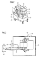
- Fig. 2 shows a mobile cleaning device for cleaning components of a burner 10.
- This essentially comprises a closable pressure vessel 32.
- the pressure vessel 32 may be configured as a housing or a kind of bell. It preferably consists of a seamless steel tube. For better corrosion resistance, the housing can be coated, eg powder-coated.
- the pressure vessel 32 may be made of a steel or steel alloy or a high strength aluminum or aluminum alloy. At the pressure vessel 32 high-strength clamping bars 31 and clamping anchors are attached.
- the pressure vessel 32 is at the burner flange 58 ( Fig. 4 ) attached. This already existing holes can be used. This ensures a particularly quick and easy attachment.
- a part of a pressure vessel wall can be formed by the burner flange 58 ( Fig. 4, Fig. 5 ), so that the nozzle-side, exit-side end of the burner 10 is disposed within the pressure vessel 32.
- the first end of the burner 10, which is disposed opposite the exit-side end and intended for the supply of fuel, is then provided outside the pressure vessel 32.
- a collecting container 42 is connected. It can be directly connected to a movable base 40.
- the sump 42 may be in fluid communication with the fuel lines stand ( Fig. 3 ).
- the attachment of the burner 10 via its burner flange 58 ( Fig. 4 ), which can be pressure-tightly connected to the mobile cleaning device by means of a quick-release device.
- the pressure vessel 32 further comprises a worm gear 36, which has a self-closing closure. This is connected to the movable base 40, which contributes significantly to the mobility of the cleaning device and substantially simplifies positioning of the cleaning device.
- a mobile device contaminated burner 10 can be achieved directly on the site, on the system or in various cleaning equipment.
- Fig. 1 further shows the mobile cleaning device with a burner 10 during the blow-out.
- the mobile cleaning device furthermore has a replaceable cover 34.
- a replaceable cover 34 About this change cover 34 pilot and diffusion burners can be cleaned with the same mobile cleaning device.
- the replacement cover 34 can be made different in size, for example, with different hole pattern.
- the pilot or diffusion burner of a burner 10 is in this case with the aid of the removable cover 34 in the mobile unit. assembled. About the quick-release device of the burner flange 58 is sealed. Thus, burners 10 of different gas turbines can be operated, so that only one cleaning base body is needed.
- Fig. 3 schematically shows the cleaning of the diagonal grid 52 and the premix 48 by means of the mobile cleaning device.
- the components of the burner 10 ( Fig. 2 ) are nozzle side into a pressure vessel 32 ( Fig.2 ), wherein the pressure vessel 32 ( Fig.2 ) is closed with a lid 46.
- the pressure vessel 32 (FIG. Fig.2 ) an inlet port 60, which preferably at the downstream End of the pressure vessel 32 ( Fig. 2 ) is attached.
- compressed air 44 is injected by means of a compressed air device (not shown). The compressed air 44 flows into the pressure vessel 32 (FIG. Fig.
- the air thus flows - in relation to the otherwise flowing fuel - in the reverse direction, so that the blown out with the air particles 44 exit through the first end of the burner 10.
- the air flow 44 can be applied pulsating to prevent the deposited deposit particles of deposits deposit in a line crease.
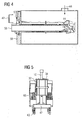
- Fig. 4 shows the cleaning by means of compressed air 44 of the oil passage 50.
- the premixing gas line 48 (FIG. Fig. 3 ) closed with a plug 56.
- 58 outlets must be sealed pressure-tight at the burner flange.
- Fig. 5 shows again schematically the attachment of the pressure vessel 32 to the flange 58 from above.
- the simple assembly is illustrated.
- the Ausblasecardi down ( Fig.1 ).
- the burner 10 can be rotated after assembly, for example, by means of the worm gear 36 in Ausblaseoplasty.
- the mobile cleaning device can be operated with compressed air 44 or with a rinsing liquid.
- the component is cleaned by rinsing with a liquid under elevated pressure.
- the burner 10 is screwed with its flange to a pressure vessel.
- the seal is made by an O-ring (not shown), with which the burner is sealed in the gas turbine.
- the pressure vessel 32 may instead of or in addition to an inlet opening have the following two connections: to the first a connection piece (not shown) for a pump, to the second a vent opening (not shown).
- the vent opening is opened during filling of the pressure vessel 32 with rinsing liquid and closed during rinsing.
- the pump By means of the pump, the required pressure is built up in the rinsing liquid, so that the liquid flows against the flow direction of the fuel through the burner 10 and thus entrains deposits with it.
- the pump is preferably also connected to a container for cleaning fluid. Suitable rinsing liquids are, for example, organic acids which can be reused after purification.
- the liquid thus flows through the burner 10 into the collecting container 42 and tears open dissolved particles With.
- An increase in the cleaning effect can be achieved by a pulsating flow. This can be achieved for example via a connected pulser. Due to the pulsating mode of operation, impurities in dead spaces of the flow are also reached and removed. A further increase in the cleaning effect can be achieved by reversing the flow.
- the liquid After rinsing with the rinsing liquid, the liquid is sucked off and the connection piece is closed to dry the component for the pump. Compressed air is introduced into the tank through the vent, which is then passed through the component, e.g. the diagonal grid flows and dries this and removes any remaining impurities.
- the rinsing liquid and the compressed air may have particles which have an abrasive effect and thus mechanically remove deposits from the walls. If a rinsing liquid or compressed air with particles has been used, it is advantageous, after cleaning, to rinse out the burner 10 with a rinsing liquid without particles or compressed air without particles.
- the "back blowing" of the burner 10 with rinsing liquid and compressed air can thus also be carried out together as a method.
- This provides a highly efficient, two-step purification process.
- the cleaning of the burner 10, in particular the Diagonalgitters 52 and the individual fuel nozzles and the thus in flow communication inner fuel lines of the burner 10 by flushing the burner fuel lines with a rinsing liquid under elevated pressure, wherein the flow in the reverse Direction - also referred to the fuel flow direction - takes place.
- the deposits are dissolved in the interior of the burner 10 and transported away.
- the air flows in - in relation to the otherwise flowing fuel - in the reverse direction, so that the air-blown particles emerge, so to speak, backwards out of the burner.
- the compressed air 44 can also pulsate in order to prevent the dissolved particles from depositing in a line bend.
- Both steps can be carried out in a single cleaning device or in two different cleaning devices.
- backward blowing with rinsing liquid or compressed air can also be performed separately.
- the invention provides a highly efficient method for cleaning components of a burner, which can comprise two steps.
- the first step is mainly for the dissolution of the particles from the base material of the burner and their removal and the second step is mainly used for drying and removal of the remaining particles.
- the mobility of the cleaning device results in rapid availability of the device at different locations. It can be cleaned by changing the cover with a body different burners of different types of machines. Also, different types of burners such as pilot and diffusion burners can be cleaned. In particular, the cleaning of a pilot burner, in particular a premixed pilot burner, which has even smaller mixing nozzles than the already clogged diffusion burner, can be blown out with the mobile unit. This is particularly advantageous because for pilot burners (diffused and premixed) there is currently no satisfactory solution, deposits efficiently remove from the component.
- the inventive method can now be dispensed with the disassembly of the burner into individual modules. Furthermore, new component components or manual cleaning are no longer necessary.
Landscapes
- Engineering & Computer Science (AREA)
- Chemical & Material Sciences (AREA)
- Mechanical Engineering (AREA)
- Chemical Kinetics & Catalysis (AREA)
- Life Sciences & Earth Sciences (AREA)
- Emergency Medicine (AREA)
- Health & Medical Sciences (AREA)
- Oil, Petroleum & Natural Gas (AREA)
- Wood Science & Technology (AREA)
- Organic Chemistry (AREA)
- Cleaning By Liquid Or Steam (AREA)
- Nozzles For Spraying Of Liquid Fuel (AREA)
- Cleaning In General (AREA)
- Gas Burners (AREA)
Claims (5)
- Procédé de nettoyage de pièce d'un brûleur (10), le brûleur (10) ayant en fonctionnement de combustion un sens d'écoulement d'origine, le brûleur (10) ayant une buse du côté de la sortie dans le sens d'écoulement d'origine, le brûleur (10) étant raccordé du côté de la buse à un dispositif de nettoyage mobile, la pièce à nettoyer étant exposée à un soufflage de manière à détacher des dépôts et à les souffler,
caractérisé en ce que le dispositif de nettoyage comporte une cuve (32) tenant la pression pouvant être fermée et ayant un couvercle (34) interchangeable et des brûleurs (10) différents peuvent être montés dans le dispositif de nettoyage mobile à l'aide du couvercle (34) interchangeable, de manière à ce que des brûleurs (10) différents puissent être nettoyés par un seul et même dispositif de nettoyage mobile, l'extrémité du côté de la buse du brûleur (10) étant disposée à l'intérieur de la cuve (32) tenant la pression et la première extrémité du brûleur (10), opposée à l'extrémité du côté de la sortie et prévue pour l'apport de combustible, étant prévue à l'extérieur de la cuve (32) tenant la pression de sorte que la pièce à nettoyer est soumise à un soufflage dans le sens contraire au sens d'écoulement du combustible. - Procédé de nettoyage de pièce d'un brûleur (10) suivant la revendication 1, caractérisé en ce qu'on effectue le soufflage au moyen d'un liquide de lavage sous une pression augmentée.
- Procédé de nettoyage de pièce d'un brûleur (10) suivant l'une des revendications 1 ou 2,
caractérisé en ce qu'on effectue le soufflage au moyen d'air (44) comprimé sous haute pression. - Procédé de nettoyage de pièce d'un brûleur (10) suivant la revendication 3,
caractérisé en ce que l'air (44) comprimé comporte des particules. - Procédé de nettoyage de pièce d'un brûleur (10) suivant la revendication 2,
caractérisé en ce que le liquide de lavage comporte des particules.
Applications Claiming Priority (2)
| Application Number | Priority Date | Filing Date | Title |
|---|---|---|---|
| DE102007056803 | 2007-11-23 | ||
| PCT/EP2008/008263 WO2009065462A2 (fr) | 2007-11-23 | 2008-09-29 | Dispositif mobile et procédé de nettoyage |
Publications (2)
| Publication Number | Publication Date |
|---|---|
| EP2212036A2 EP2212036A2 (fr) | 2010-08-04 |
| EP2212036B1 true EP2212036B1 (fr) | 2015-08-26 |
Family
ID=40513764
Family Applications (1)
| Application Number | Title | Priority Date | Filing Date |
|---|---|---|---|
| EP08852747.8A Not-in-force EP2212036B1 (fr) | 2007-11-23 | 2008-09-29 | Procédé de nettoyage |
Country Status (5)
| Country | Link |
|---|---|
| US (1) | US8632639B2 (fr) |
| EP (1) | EP2212036B1 (fr) |
| CN (1) | CN101873897B (fr) |
| RU (1) | RU2465971C2 (fr) |
| WO (4) | WO2009065449A2 (fr) |
Families Citing this family (13)
| Publication number | Priority date | Publication date | Assignee | Title |
|---|---|---|---|---|
| WO2009065449A2 (fr) * | 2007-11-23 | 2009-05-28 | Siemens Aktiengesellschaft | Procédé et dispositif de nettoyage d'un composant à haute température de grande dimension |
| ITMI20092189A1 (it) * | 2009-12-15 | 2011-06-16 | Ansaldo Energia Spa | Metodo per la pulizia di bruciatori e/o parti di bruciatore di una turbina a gas |
| CN102310062B (zh) * | 2011-01-15 | 2014-04-02 | 合肥市百胜科技发展股份有限公司 | 测径仪入口清洁装置 |
| US9932854B1 (en) * | 2013-12-09 | 2018-04-03 | General Electric Company | Methods of cleaning a hot gas flowpath component of a turbine engine |
| US9926517B2 (en) | 2013-12-09 | 2018-03-27 | General Electric Company | Cleaning solution and methods of cleaning a turbine engine |
| DE102014200119A1 (de) * | 2014-01-08 | 2015-07-09 | Siemens Aktiengesellschaft | Verfahren zum Reinigen von Oberflächen eines Brenners |
| BR102016021259B1 (pt) | 2015-10-05 | 2022-06-14 | General Electric Company | Método e soluções de limpeza de um motor de turbina e composição de reagente |
| US9951647B2 (en) | 2015-12-17 | 2018-04-24 | General Electric Company | System and method for in situ cleaning of internal components of a gas turbine engine and a related plug assembly |
| EP3312152B1 (fr) * | 2016-10-21 | 2021-03-10 | Rolls-Royce Corporation | Enlèvement de revêtements de substrats céramiques ou composites à matrice céramique |
| US10731508B2 (en) | 2017-03-07 | 2020-08-04 | General Electric Company | Method for cleaning components of a turbine engine |
| RU2696432C1 (ru) * | 2018-11-29 | 2019-08-01 | Общество с ограниченной ответственностью "Газпром трансгаз Ухта" | Способ очистки горелочных устройств индивидуальных камер сгорания предварительного смешения топлива и установка для его применения |
| RU2732253C1 (ru) * | 2019-12-27 | 2020-09-14 | Открытое акционерное общество "Газпром трансгаз Беларусь" | Способ очистки горелочного устройства камеры сгорания и установка для его применения |
| CN115415247B (zh) * | 2022-08-17 | 2024-08-06 | 安徽天思朴超精密模具有限公司 | 一种机械零件加工用集清扫、吹气于一体的金属碎屑清除装置 |
Family Cites Families (23)
| Publication number | Priority date | Publication date | Assignee | Title |
|---|---|---|---|---|
| US2948092A (en) * | 1955-03-04 | 1960-08-09 | Lawrence J Fuller | Method for cleaning jet and gas turbine engines |
| US4167193A (en) * | 1977-10-11 | 1979-09-11 | Magnus Harve W | Apparatus for cleaning jet engine nozzles |
| SU1447268A3 (ru) * | 1986-11-13 | 1988-12-23 | Вап Райнигунгсзюстеме Гмбх Унд Ко. (Фирма) | Очистное устройство высокого давлени |
| DE3728771A1 (de) * | 1987-08-28 | 1989-03-09 | Henkel Kgaa | Verbessertes verfahren zur ultraschall-reinigung von festen formteilen |
| US4995915A (en) | 1988-07-15 | 1991-02-26 | The Dow Chemical Company | Cleaning gas turbine fuel nozzles |
| SE468833B (sv) * | 1991-05-21 | 1993-03-29 | Bengt Olsson | Apparat foer tvaettning av verkstadsgods |
| US5339845A (en) * | 1993-07-26 | 1994-08-23 | Fuel Systems Textron, Inc. | Cleaning apparatus and method for fuel and other passages |
| US5464479A (en) * | 1994-08-31 | 1995-11-07 | Kenton; Donald J. | Method for removing undesired material from internal spaces of parts |
| US6491044B1 (en) * | 1997-05-23 | 2002-12-10 | Shelba F. Bowsman | Thorough air induction, fuel injection and decarbonization cleaning machine and process that requires no disassembly of the engine or its components which uses compressed air at its source of power |
| DE19817205A1 (de) * | 1998-04-17 | 1999-10-21 | Moessner Druckguswerk Gmbh | Reinigungsverfahren sowie Reinigungsbad |
| EP1199453A3 (fr) * | 1998-05-08 | 2003-01-22 | Mitsubishi Heavy Industries, Ltd. | Système de lavage des injecteurs de carburant d'une turbine à gaz |
| DE19832767A1 (de) * | 1998-07-22 | 2000-01-27 | Siemens Ag | Vorrichtung sowie Verfahren zur Reinigung eines hohlen Bauteils einer Strömungsmaschine |
| FR2791282B1 (fr) * | 1999-03-23 | 2001-05-11 | Forward Tech Industries Sa | Procede de nettoyage ou de debourrage d'une piece de fonderie |
| US20020103093A1 (en) * | 2000-12-05 | 2002-08-01 | Lagraff John Robert | Method and composition for cleaning a turbine engine component |
| US6500269B2 (en) * | 2001-01-29 | 2002-12-31 | General Electric Company | Method of cleaning turbine component using laser shock peening |
| US6616771B2 (en) * | 2001-11-30 | 2003-09-09 | Forhealth Technologies, Inc. | Method and system for cleaning and reusing a cannula |
| AT411264B (de) * | 2002-02-14 | 2003-11-25 | Voest Alpine Ind Anlagen | Verteilerboden zur verteilung eines mit feinen feststoffpartikeln beladenen gases |
| US6932093B2 (en) * | 2003-02-24 | 2005-08-23 | General Electric Company | Methods and apparatus for washing gas turbine engine combustors |
| US20050000550A1 (en) * | 2003-07-01 | 2005-01-06 | Tyson Fresh Meats, Inc. | Method for backflushing injector needles |
| US7198052B2 (en) * | 2004-03-12 | 2007-04-03 | General Electric Company | Mobile flushing unit and process |
| DE102005009274B3 (de) | 2005-02-25 | 2006-07-27 | Stamm, Dan, Dipl.-Ing. | Reinigungsverfahren für einen Verbrennungsraum und Vorrichtung zur Durchführung des Verfahrens |
| DE502006005350D1 (de) * | 2006-08-16 | 2009-12-24 | Siemens Ag | Brennerreinigungsvorrichtung |
| WO2009065449A2 (fr) * | 2007-11-23 | 2009-05-28 | Siemens Aktiengesellschaft | Procédé et dispositif de nettoyage d'un composant à haute température de grande dimension |
-
2008
- 2008-06-12 WO PCT/EP2008/004738 patent/WO2009065449A2/fr not_active Ceased
- 2008-09-29 EP EP08852747.8A patent/EP2212036B1/fr not_active Not-in-force
- 2008-09-29 US US12/743,052 patent/US8632639B2/en not_active Expired - Fee Related
- 2008-09-29 RU RU2010125600/05A patent/RU2465971C2/ru not_active IP Right Cessation
- 2008-09-29 WO PCT/EP2008/008263 patent/WO2009065462A2/fr not_active Ceased
- 2008-09-29 CN CN200880117427.2A patent/CN101873897B/zh not_active Expired - Fee Related
- 2008-09-30 WO PCT/EP2008/063057 patent/WO2009065657A2/fr not_active Ceased
- 2008-10-08 WO PCT/EP2008/008505 patent/WO2009065465A2/fr not_active Ceased
Also Published As
| Publication number | Publication date |
|---|---|
| WO2009065449A3 (fr) | 2009-07-09 |
| WO2009065462A2 (fr) | 2009-05-28 |
| WO2009065449A2 (fr) | 2009-05-28 |
| WO2009065465A3 (fr) | 2009-09-03 |
| WO2009065465A2 (fr) | 2009-05-28 |
| WO2009065657A2 (fr) | 2009-05-28 |
| CN101873897B (zh) | 2013-03-06 |
| WO2009065462A3 (fr) | 2009-09-24 |
| WO2009065657A3 (fr) | 2009-10-01 |
| US20100243000A1 (en) | 2010-09-30 |
| CN101873897A (zh) | 2010-10-27 |
| US8632639B2 (en) | 2014-01-21 |
| EP2212036A2 (fr) | 2010-08-04 |
| RU2010125600A (ru) | 2011-12-27 |
| RU2465971C2 (ru) | 2012-11-10 |
Similar Documents
| Publication | Publication Date | Title |
|---|---|---|
| EP2212036B1 (fr) | Procédé de nettoyage | |
| DE2514173C3 (de) | Vorrichtung zur Reinigung der wärmetauschenden Flächen der Speichermassen von umlaufenden Regenerativ-Wärmetauschern | |
| EP1892471B1 (fr) | Dispositif de nettoyage de brûleur | |
| EP2304205B1 (fr) | Procédé de rinçage d'un système d'alimentation en combustible d'une turbine à gaz et système d'alimentation en combustible associé | |
| DE69307919T2 (de) | Reinigungsgerät für wärmetauschflächen | |
| DE602005002888T2 (de) | Flexodruckmaschine mit Farbübertragungsvorrichtung | |
| EP1431662A1 (fr) | Chambre de combustion de turbine avec système de refroidissement à circuit fermé | |
| DE2906364C2 (fr) | ||
| EP4264024B1 (fr) | Dispositif de nettoyage et procédé de nettoyage d'un agencement de filtre | |
| WO1996014127A1 (fr) | Dispositif filtrant en forme de bougie a systeme de pulverisation | |
| DE2928532A1 (de) | Anordnung und verfahren zum einspeisen einer speisefluessigkeit in ein druckgefaess | |
| DE3240721A1 (de) | Verfahren und vorrichtung zur entfernung eines haftenden niederschlages von der erwaermten flaeche eines waermetauschers oder dergleichen | |
| DE102005019285B3 (de) | Reinigungsanlage für spanend bearbeitete Werkstücke | |
| EP2110517A1 (fr) | Procédé destiné à éliminer les dépôts de composants haute température et un dispositif | |
| EP0724917A1 (fr) | Dispositif pour nettoyer les surfaces intérieures d'un tonneau à vin | |
| EP4186602B1 (fr) | Procédé et dispositif de nettoyage des conduites ou des systèmes au moyen des impulsions de gaz comprimé modulant | |
| DE19515291C2 (de) | Vorrichtung zur Reinigung von Wärmeaustauschern | |
| DE10226685A1 (de) | Heizgerät mit Brenner und Wärmeübertrager | |
| DE102010005760A1 (de) | Wellrohr-Innenreinigung und Vorrichtung dazu | |
| DE316083C (fr) | ||
| DE269793C (fr) | ||
| DE102017112001A1 (de) | Vorrichtung zum Reinigen von Oberflächen | |
| EP2110518A1 (fr) | Procédé de nettoyage d'un composant haute température et un dispositif associée | |
| DE2316074C3 (de) | Einrichtung zur Inspektion und Durchführung eventueller Reparaturarbeiten am Rohrbündel von Dampferzeugern | |
| EP2127764A1 (fr) | Procédé et dispositif de nettoyage d'un composant haute température |
Legal Events
| Date | Code | Title | Description |
|---|---|---|---|
| PUAI | Public reference made under article 153(3) epc to a published international application that has entered the european phase |
Free format text: ORIGINAL CODE: 0009012 |
|
| 17P | Request for examination filed |
Effective date: 20100429 |
|
| AK | Designated contracting states |
Kind code of ref document: A2 Designated state(s): AT BE BG CH CY CZ DE DK EE ES FI FR GB GR HR HU IE IS IT LI LT LU LV MC MT NL NO PL PT RO SE SI SK TR |
|
| AX | Request for extension of the european patent |
Extension state: AL BA MK RS |
|
| DAX | Request for extension of the european patent (deleted) | ||
| RAP1 | Party data changed (applicant data changed or rights of an application transferred) |
Owner name: SIEMENS AKTIENGESELLSCHAFT |
|
| GRAP | Despatch of communication of intention to grant a patent |
Free format text: ORIGINAL CODE: EPIDOSNIGR1 |
|
| RIC1 | Information provided on ipc code assigned before grant |
Ipc: F01D 25/00 20060101ALI20150226BHEP Ipc: B08B 3/04 20060101AFI20150226BHEP Ipc: C11D 7/26 20060101ALI20150226BHEP Ipc: B08B 9/00 20060101ALI20150226BHEP Ipc: B08B 9/027 20060101ALI20150226BHEP Ipc: C11D 11/00 20060101ALI20150226BHEP |
|
| INTG | Intention to grant announced |
Effective date: 20150323 |
|
| GRAS | Grant fee paid |
Free format text: ORIGINAL CODE: EPIDOSNIGR3 |
|
| GRAA | (expected) grant |
Free format text: ORIGINAL CODE: 0009210 |
|
| AK | Designated contracting states |
Kind code of ref document: B1 Designated state(s): AT BE BG CH CY CZ DE DK EE ES FI FR GB GR HR HU IE IS IT LI LT LU LV MC MT NL NO PL PT RO SE SI SK TR |
|
| REG | Reference to a national code |
Ref country code: GB Ref legal event code: FG4D Free format text: NOT ENGLISH |
|
| REG | Reference to a national code |
Ref country code: CH Ref legal event code: EP |
|
| REG | Reference to a national code |
Ref country code: AT Ref legal event code: REF Ref document number: 744861 Country of ref document: AT Kind code of ref document: T Effective date: 20150915 |
|
| REG | Reference to a national code |
Ref country code: IE Ref legal event code: FG4D Free format text: LANGUAGE OF EP DOCUMENT: GERMAN |
|
| REG | Reference to a national code |
Ref country code: DE Ref legal event code: R096 Ref document number: 502008013323 Country of ref document: DE |
|
| REG | Reference to a national code |
Ref country code: LT Ref legal event code: MG4D |
|
| PG25 | Lapsed in a contracting state [announced via postgrant information from national office to epo] |
Ref country code: LV Free format text: LAPSE BECAUSE OF FAILURE TO SUBMIT A TRANSLATION OF THE DESCRIPTION OR TO PAY THE FEE WITHIN THE PRESCRIBED TIME-LIMIT Effective date: 20150826 Ref country code: NO Free format text: LAPSE BECAUSE OF FAILURE TO SUBMIT A TRANSLATION OF THE DESCRIPTION OR TO PAY THE FEE WITHIN THE PRESCRIBED TIME-LIMIT Effective date: 20151126 Ref country code: FI Free format text: LAPSE BECAUSE OF FAILURE TO SUBMIT A TRANSLATION OF THE DESCRIPTION OR TO PAY THE FEE WITHIN THE PRESCRIBED TIME-LIMIT Effective date: 20150826 Ref country code: LT Free format text: LAPSE BECAUSE OF FAILURE TO SUBMIT A TRANSLATION OF THE DESCRIPTION OR TO PAY THE FEE WITHIN THE PRESCRIBED TIME-LIMIT Effective date: 20150826 Ref country code: GR Free format text: LAPSE BECAUSE OF FAILURE TO SUBMIT A TRANSLATION OF THE DESCRIPTION OR TO PAY THE FEE WITHIN THE PRESCRIBED TIME-LIMIT Effective date: 20151127 |
|
| PGFP | Annual fee paid to national office [announced via postgrant information from national office to epo] |
Ref country code: DE Payment date: 20151120 Year of fee payment: 8 Ref country code: IT Payment date: 20151027 Year of fee payment: 8 |
|
| REG | Reference to a national code |
Ref country code: NL Ref legal event code: MP Effective date: 20150826 |
|
| PG25 | Lapsed in a contracting state [announced via postgrant information from national office to epo] |
Ref country code: SE Free format text: LAPSE BECAUSE OF FAILURE TO SUBMIT A TRANSLATION OF THE DESCRIPTION OR TO PAY THE FEE WITHIN THE PRESCRIBED TIME-LIMIT Effective date: 20150826 Ref country code: IS Free format text: LAPSE BECAUSE OF FAILURE TO SUBMIT A TRANSLATION OF THE DESCRIPTION OR TO PAY THE FEE WITHIN THE PRESCRIBED TIME-LIMIT Effective date: 20151226 Ref country code: PT Free format text: LAPSE BECAUSE OF FAILURE TO SUBMIT A TRANSLATION OF THE DESCRIPTION OR TO PAY THE FEE WITHIN THE PRESCRIBED TIME-LIMIT Effective date: 20151228 Ref country code: PL Free format text: LAPSE BECAUSE OF FAILURE TO SUBMIT A TRANSLATION OF THE DESCRIPTION OR TO PAY THE FEE WITHIN THE PRESCRIBED TIME-LIMIT Effective date: 20150826 Ref country code: HR Free format text: LAPSE BECAUSE OF FAILURE TO SUBMIT A TRANSLATION OF THE DESCRIPTION OR TO PAY THE FEE WITHIN THE PRESCRIBED TIME-LIMIT Effective date: 20150826 Ref country code: ES Free format text: LAPSE BECAUSE OF FAILURE TO SUBMIT A TRANSLATION OF THE DESCRIPTION OR TO PAY THE FEE WITHIN THE PRESCRIBED TIME-LIMIT Effective date: 20150826 |
|
| PG25 | Lapsed in a contracting state [announced via postgrant information from national office to epo] |
Ref country code: NL Free format text: LAPSE BECAUSE OF FAILURE TO SUBMIT A TRANSLATION OF THE DESCRIPTION OR TO PAY THE FEE WITHIN THE PRESCRIBED TIME-LIMIT Effective date: 20150826 |
|
| PG25 | Lapsed in a contracting state [announced via postgrant information from national office to epo] |
Ref country code: CZ Free format text: LAPSE BECAUSE OF FAILURE TO SUBMIT A TRANSLATION OF THE DESCRIPTION OR TO PAY THE FEE WITHIN THE PRESCRIBED TIME-LIMIT Effective date: 20150826 Ref country code: DK Free format text: LAPSE BECAUSE OF FAILURE TO SUBMIT A TRANSLATION OF THE DESCRIPTION OR TO PAY THE FEE WITHIN THE PRESCRIBED TIME-LIMIT Effective date: 20150826 Ref country code: EE Free format text: LAPSE BECAUSE OF FAILURE TO SUBMIT A TRANSLATION OF THE DESCRIPTION OR TO PAY THE FEE WITHIN THE PRESCRIBED TIME-LIMIT Effective date: 20150826 Ref country code: SK Free format text: LAPSE BECAUSE OF FAILURE TO SUBMIT A TRANSLATION OF THE DESCRIPTION OR TO PAY THE FEE WITHIN THE PRESCRIBED TIME-LIMIT Effective date: 20150826 |
|
| REG | Reference to a national code |
Ref country code: CH Ref legal event code: PL |
|
| REG | Reference to a national code |
Ref country code: DE Ref legal event code: R097 Ref document number: 502008013323 Country of ref document: DE |
|
| PG25 | Lapsed in a contracting state [announced via postgrant information from national office to epo] |
Ref country code: RO Free format text: LAPSE BECAUSE OF FAILURE TO SUBMIT A TRANSLATION OF THE DESCRIPTION OR TO PAY THE FEE WITHIN THE PRESCRIBED TIME-LIMIT Effective date: 20150826 Ref country code: MC Free format text: LAPSE BECAUSE OF FAILURE TO SUBMIT A TRANSLATION OF THE DESCRIPTION OR TO PAY THE FEE WITHIN THE PRESCRIBED TIME-LIMIT Effective date: 20150826 |
|
| REG | Reference to a national code |
Ref country code: IE Ref legal event code: MM4A |
|
| PLBE | No opposition filed within time limit |
Free format text: ORIGINAL CODE: 0009261 |
|
| REG | Reference to a national code |
Ref country code: FR Ref legal event code: ST Effective date: 20160531 |
|
| STAA | Information on the status of an ep patent application or granted ep patent |
Free format text: STATUS: NO OPPOSITION FILED WITHIN TIME LIMIT |
|
| GBPC | Gb: european patent ceased through non-payment of renewal fee |
Effective date: 20151126 |
|
| PG25 | Lapsed in a contracting state [announced via postgrant information from national office to epo] |
Ref country code: CH Free format text: LAPSE BECAUSE OF NON-PAYMENT OF DUE FEES Effective date: 20150930 Ref country code: IE Free format text: LAPSE BECAUSE OF NON-PAYMENT OF DUE FEES Effective date: 20150929 Ref country code: LI Free format text: LAPSE BECAUSE OF NON-PAYMENT OF DUE FEES Effective date: 20150930 |
|
| 26N | No opposition filed |
Effective date: 20160530 |
|
| PG25 | Lapsed in a contracting state [announced via postgrant information from national office to epo] |
Ref country code: SI Free format text: LAPSE BECAUSE OF FAILURE TO SUBMIT A TRANSLATION OF THE DESCRIPTION OR TO PAY THE FEE WITHIN THE PRESCRIBED TIME-LIMIT Effective date: 20150826 Ref country code: FR Free format text: LAPSE BECAUSE OF NON-PAYMENT OF DUE FEES Effective date: 20151026 |
|
| PG25 | Lapsed in a contracting state [announced via postgrant information from national office to epo] |
Ref country code: GB Free format text: LAPSE BECAUSE OF NON-PAYMENT OF DUE FEES Effective date: 20151126 |
|
| REG | Reference to a national code |
Ref country code: AT Ref legal event code: MM01 Ref document number: 744861 Country of ref document: AT Kind code of ref document: T Effective date: 20150929 |
|
| PG25 | Lapsed in a contracting state [announced via postgrant information from national office to epo] |
Ref country code: AT Free format text: LAPSE BECAUSE OF NON-PAYMENT OF DUE FEES Effective date: 20150929 |
|
| PG25 | Lapsed in a contracting state [announced via postgrant information from national office to epo] |
Ref country code: MT Free format text: LAPSE BECAUSE OF FAILURE TO SUBMIT A TRANSLATION OF THE DESCRIPTION OR TO PAY THE FEE WITHIN THE PRESCRIBED TIME-LIMIT Effective date: 20150826 |
|
| REG | Reference to a national code |
Ref country code: DE Ref legal event code: R119 Ref document number: 502008013323 Country of ref document: DE |
|
| PG25 | Lapsed in a contracting state [announced via postgrant information from national office to epo] |
Ref country code: BG Free format text: LAPSE BECAUSE OF FAILURE TO SUBMIT A TRANSLATION OF THE DESCRIPTION OR TO PAY THE FEE WITHIN THE PRESCRIBED TIME-LIMIT Effective date: 20150826 Ref country code: HU Free format text: LAPSE BECAUSE OF FAILURE TO SUBMIT A TRANSLATION OF THE DESCRIPTION OR TO PAY THE FEE WITHIN THE PRESCRIBED TIME-LIMIT; INVALID AB INITIO Effective date: 20080929 |
|
| PG25 | Lapsed in a contracting state [announced via postgrant information from national office to epo] |
Ref country code: CY Free format text: LAPSE BECAUSE OF FAILURE TO SUBMIT A TRANSLATION OF THE DESCRIPTION OR TO PAY THE FEE WITHIN THE PRESCRIBED TIME-LIMIT Effective date: 20150826 |
|
| PG25 | Lapsed in a contracting state [announced via postgrant information from national office to epo] |
Ref country code: BE Free format text: LAPSE BECAUSE OF NON-PAYMENT OF DUE FEES Effective date: 20150930 Ref country code: DE Free format text: LAPSE BECAUSE OF NON-PAYMENT OF DUE FEES Effective date: 20170401 |
|
| PG25 | Lapsed in a contracting state [announced via postgrant information from national office to epo] |
Ref country code: IT Free format text: LAPSE BECAUSE OF NON-PAYMENT OF DUE FEES Effective date: 20160929 Ref country code: TR Free format text: LAPSE BECAUSE OF FAILURE TO SUBMIT A TRANSLATION OF THE DESCRIPTION OR TO PAY THE FEE WITHIN THE PRESCRIBED TIME-LIMIT Effective date: 20150826 |
|
| PG25 | Lapsed in a contracting state [announced via postgrant information from national office to epo] |
Ref country code: LU Free format text: LAPSE BECAUSE OF NON-PAYMENT OF DUE FEES Effective date: 20150929 |