EP2212145B1 - Modularer kraftstofftank und verfahren zur herstellung eines modularen kraftstofftanks - Google Patents
Modularer kraftstofftank und verfahren zur herstellung eines modularen kraftstofftanks Download PDFInfo
- Publication number
- EP2212145B1 EP2212145B1 EP07835109A EP07835109A EP2212145B1 EP 2212145 B1 EP2212145 B1 EP 2212145B1 EP 07835109 A EP07835109 A EP 07835109A EP 07835109 A EP07835109 A EP 07835109A EP 2212145 B1 EP2212145 B1 EP 2212145B1
- Authority
- EP
- European Patent Office
- Prior art keywords
- modules
- module
- tank
- bowl
- open end
- Prior art date
- Legal status (The legal status is an assumption and is not a legal conclusion. Google has not performed a legal analysis and makes no representation as to the accuracy of the status listed.)
- Not-in-force
Links
- 239000002828 fuel tank Substances 0.000 title claims abstract description 31
- 238000004519 manufacturing process Methods 0.000 title claims description 11
- 239000000446 fuel Substances 0.000 claims abstract description 26
- 238000004891 communication Methods 0.000 claims abstract description 7
- 238000000465 moulding Methods 0.000 claims abstract description 4
- 238000000034 method Methods 0.000 claims description 13
- 238000001746 injection moulding Methods 0.000 claims description 9
- 239000000463 material Substances 0.000 claims description 9
- 230000002787 reinforcement Effects 0.000 claims description 6
- 238000005476 soldering Methods 0.000 claims description 5
- 238000003466 welding Methods 0.000 claims description 5
- 238000004026 adhesive bonding Methods 0.000 claims description 4
- 238000000071 blow moulding Methods 0.000 description 4
- 239000000945 filler Substances 0.000 description 3
- 238000007789 sealing Methods 0.000 description 3
- 238000007796 conventional method Methods 0.000 description 2
- 230000003247 decreasing effect Effects 0.000 description 2
- 238000013461 design Methods 0.000 description 2
- 238000005516 engineering process Methods 0.000 description 2
- 239000007788 liquid Substances 0.000 description 2
- 239000002184 metal Substances 0.000 description 2
- 239000011324 bead Substances 0.000 description 1
- 230000002860 competitive effect Effects 0.000 description 1
- 230000000694 effects Effects 0.000 description 1
- 239000012530 fluid Substances 0.000 description 1
- 239000003292 glue Substances 0.000 description 1
- 238000010438 heat treatment Methods 0.000 description 1
- 238000002347 injection Methods 0.000 description 1
- 239000007924 injection Substances 0.000 description 1
- 238000003780 insertion Methods 0.000 description 1
- 230000037431 insertion Effects 0.000 description 1
- 238000012986 modification Methods 0.000 description 1
- 230000004048 modification Effects 0.000 description 1
- 238000005192 partition Methods 0.000 description 1
- 239000000725 suspension Substances 0.000 description 1
Images



Classifications
-
- B—PERFORMING OPERATIONS; TRANSPORTING
- B60—VEHICLES IN GENERAL
- B60K—ARRANGEMENT OR MOUNTING OF PROPULSION UNITS OR OF TRANSMISSIONS IN VEHICLES; ARRANGEMENT OR MOUNTING OF PLURAL DIVERSE PRIME-MOVERS IN VEHICLES; AUXILIARY DRIVES FOR VEHICLES; INSTRUMENTATION OR DASHBOARDS FOR VEHICLES; ARRANGEMENTS IN CONNECTION WITH COOLING, AIR INTAKE, GAS EXHAUST OR FUEL SUPPLY OF PROPULSION UNITS IN VEHICLES
- B60K15/00—Arrangement in connection with fuel supply of combustion engines or other fuel consuming energy converters, e.g. fuel cells; Mounting or construction of fuel tanks
- B60K15/03—Fuel tanks
- B60K15/03177—Fuel tanks made of non-metallic material, e.g. plastics, or of a combination of non-metallic and metallic material
-
- B—PERFORMING OPERATIONS; TRANSPORTING
- B60—VEHICLES IN GENERAL
- B60K—ARRANGEMENT OR MOUNTING OF PROPULSION UNITS OR OF TRANSMISSIONS IN VEHICLES; ARRANGEMENT OR MOUNTING OF PLURAL DIVERSE PRIME-MOVERS IN VEHICLES; AUXILIARY DRIVES FOR VEHICLES; INSTRUMENTATION OR DASHBOARDS FOR VEHICLES; ARRANGEMENTS IN CONNECTION WITH COOLING, AIR INTAKE, GAS EXHAUST OR FUEL SUPPLY OF PROPULSION UNITS IN VEHICLES
- B60K15/00—Arrangement in connection with fuel supply of combustion engines or other fuel consuming energy converters, e.g. fuel cells; Mounting or construction of fuel tanks
- B60K15/03—Fuel tanks
- B60K15/063—Arrangement of tanks
-
- B—PERFORMING OPERATIONS; TRANSPORTING
- B60—VEHICLES IN GENERAL
- B60K—ARRANGEMENT OR MOUNTING OF PROPULSION UNITS OR OF TRANSMISSIONS IN VEHICLES; ARRANGEMENT OR MOUNTING OF PLURAL DIVERSE PRIME-MOVERS IN VEHICLES; AUXILIARY DRIVES FOR VEHICLES; INSTRUMENTATION OR DASHBOARDS FOR VEHICLES; ARRANGEMENTS IN CONNECTION WITH COOLING, AIR INTAKE, GAS EXHAUST OR FUEL SUPPLY OF PROPULSION UNITS IN VEHICLES
- B60K15/00—Arrangement in connection with fuel supply of combustion engines or other fuel consuming energy converters, e.g. fuel cells; Mounting or construction of fuel tanks
- B60K15/03—Fuel tanks
- B60K2015/03118—Multiple tanks, i.e. two or more separate tanks
-
- B—PERFORMING OPERATIONS; TRANSPORTING
- B60—VEHICLES IN GENERAL
- B60K—ARRANGEMENT OR MOUNTING OF PROPULSION UNITS OR OF TRANSMISSIONS IN VEHICLES; ARRANGEMENT OR MOUNTING OF PLURAL DIVERSE PRIME-MOVERS IN VEHICLES; AUXILIARY DRIVES FOR VEHICLES; INSTRUMENTATION OR DASHBOARDS FOR VEHICLES; ARRANGEMENTS IN CONNECTION WITH COOLING, AIR INTAKE, GAS EXHAUST OR FUEL SUPPLY OF PROPULSION UNITS IN VEHICLES
- B60K15/00—Arrangement in connection with fuel supply of combustion engines or other fuel consuming energy converters, e.g. fuel cells; Mounting or construction of fuel tanks
- B60K15/03—Fuel tanks
- B60K2015/03118—Multiple tanks, i.e. two or more separate tanks
- B60K2015/03144—Fluid connections between the tanks
-
- B—PERFORMING OPERATIONS; TRANSPORTING
- B60—VEHICLES IN GENERAL
- B60K—ARRANGEMENT OR MOUNTING OF PROPULSION UNITS OR OF TRANSMISSIONS IN VEHICLES; ARRANGEMENT OR MOUNTING OF PLURAL DIVERSE PRIME-MOVERS IN VEHICLES; AUXILIARY DRIVES FOR VEHICLES; INSTRUMENTATION OR DASHBOARDS FOR VEHICLES; ARRANGEMENTS IN CONNECTION WITH COOLING, AIR INTAKE, GAS EXHAUST OR FUEL SUPPLY OF PROPULSION UNITS IN VEHICLES
- B60K15/00—Arrangement in connection with fuel supply of combustion engines or other fuel consuming energy converters, e.g. fuel cells; Mounting or construction of fuel tanks
- B60K15/03—Fuel tanks
- B60K2015/03164—Modular concepts for fuel tanks
-
- B—PERFORMING OPERATIONS; TRANSPORTING
- B60—VEHICLES IN GENERAL
- B60K—ARRANGEMENT OR MOUNTING OF PROPULSION UNITS OR OF TRANSMISSIONS IN VEHICLES; ARRANGEMENT OR MOUNTING OF PLURAL DIVERSE PRIME-MOVERS IN VEHICLES; AUXILIARY DRIVES FOR VEHICLES; INSTRUMENTATION OR DASHBOARDS FOR VEHICLES; ARRANGEMENTS IN CONNECTION WITH COOLING, AIR INTAKE, GAS EXHAUST OR FUEL SUPPLY OF PROPULSION UNITS IN VEHICLES
- B60K15/00—Arrangement in connection with fuel supply of combustion engines or other fuel consuming energy converters, e.g. fuel cells; Mounting or construction of fuel tanks
- B60K15/03—Fuel tanks
- B60K2015/03328—Arrangements or special measures related to fuel tanks or fuel handling
- B60K2015/0344—Arrangements or special measures related to fuel tanks or fuel handling comprising baffles
-
- B—PERFORMING OPERATIONS; TRANSPORTING
- B60—VEHICLES IN GENERAL
- B60K—ARRANGEMENT OR MOUNTING OF PROPULSION UNITS OR OF TRANSMISSIONS IN VEHICLES; ARRANGEMENT OR MOUNTING OF PLURAL DIVERSE PRIME-MOVERS IN VEHICLES; AUXILIARY DRIVES FOR VEHICLES; INSTRUMENTATION OR DASHBOARDS FOR VEHICLES; ARRANGEMENTS IN CONNECTION WITH COOLING, AIR INTAKE, GAS EXHAUST OR FUEL SUPPLY OF PROPULSION UNITS IN VEHICLES
- B60K15/00—Arrangement in connection with fuel supply of combustion engines or other fuel consuming energy converters, e.g. fuel cells; Mounting or construction of fuel tanks
- B60K15/03—Fuel tanks
- B60K2015/03328—Arrangements or special measures related to fuel tanks or fuel handling
- B60K2015/03447—Arrangements or special measures related to fuel tanks or fuel handling for improving the sealing
-
- B—PERFORMING OPERATIONS; TRANSPORTING
- B60—VEHICLES IN GENERAL
- B60Y—INDEXING SCHEME RELATING TO ASPECTS CROSS-CUTTING VEHICLE TECHNOLOGY
- B60Y2200/00—Type of vehicle
- B60Y2200/10—Road Vehicles
- B60Y2200/14—Trucks; Load vehicles, Busses
Definitions
- the present invention relates to a heavy vehicle modular fuel tank, comprising a plurality of bowl shaped modules having an open end and a bowl end, which modules are connected to one another in a row in a longitudinal direction with the open end of one module facing the bowl end of another module, each of the modules having a space for accommodating fuel and the spaces being in communication with each other by means of holes in the bowl ends.
- Fuel tanks are no exception. Cheaper, lighter plastic tanks instead of traditional metal tanks can be found on vehicles on the streets today.
- Tanks for heavy vehicles with a fuel volume of perhaps 300-800 litres or more, are however subjected to vibrations and strong forces as the fuel moves back and forth in the tank.
- baffle plates can be added to the tanks.
- baffle plates are commonly known, and usually these partition walls are inserted at regular intervals along the interior of the tank and provided with openings through which the fuel can flow only in limited volume.
- the baffle plates also serve to reinforce the tank, and reducing deformation of the tank as it is fixed to the vehicle mounted tank bracket.
- Plastic tanks of sizes appropriate for heavy vehicles are however commonly manufactured through rotation- or blow-molding, and with the use of these production technologies is the material thickness difficult to control, while applying baffle plates is expensive and complicated, if even feasible.
- the space available for the tank and its connections often varies from one vehicle model to another.
- the volume as well as the shape of the space available can vary from a chassis to another.
- a tank used for one vehicle model might not physically fit in the chassis of another.
- the tank described in DE 10 2005 050 803 with its identical pot- shaped elements, may vary in a longitudinal direction, it is thus likely that such a tank can not be utilized across a variety of chassis. Consequently, there remains a need for fuel tanks fulfilling harsh automotive requirements, which are easy and cost effective to produce and can be utilized across a wide variety of heavy vehicle chassis.
- WO 00/05090 teaches a vehicle tank with a varying cross section along a longitudinal direction for adapting to a space available when mounting said tank on a vehicle frame.
- the tank comprises a plurality of bowl-shaped modules, having an open end and a bowl end forming the tank by connecting the bowl end of one module to an open end of an adjacent module. Holes in the bowl ends allow flowing of liquid between said modules.
- the cross section of an open end of one module matches the cross section of a bowl end of an adjacent module, whereby the cross sections vary depending on the outer geometry of the module and the tank.
- EP 1 061 306 A1 teaches a similar tank for a vehicle as the aforementioned WO 00/05090 comprising of a plurality of rotational symmetric modules being resistant against pressure.
- the outline of a cross section of each module has a two C form, whereby length, widths and axis alignment of each module varies for adapting the tank's overall dimension to a space available in the vehicle.
- DE 44 42 780 A1 and also WO 2007/0699867 A teach a vehicle tank comprising a plurality of bowl-shaped modules, having an open end and a bowl end forming the tank by connecting the bowl end of one module to an open end of an adjacent module. Holes in the bowl ends allow flowing of liquid between said modules. All modules have a constant cross section along a longitudinal direction.
- a vehicle tank comprising a gradually formed end portion with two tapered diminutions configured such that an additional tank can be attached to the tank at either one of the diminutions by a fluid tight fastening.
- a heavy vehicle modular fuel tank comprising a plurality of bowl shaped modules having an open end and a bowl end, which modules are connected to one another in a row in a longitudinal direction with the open end of one module facing the bowl end of another module, each of the modules having a space for accommodating fuel and the spaces being in communication with each other by means of holes in the bowl ends, wherein the tank has a varying outer cross section along the longitudinal direction so as to be adapted to a space available when mounting the tank on a heavy vehicle frame.
- a method of manufacturing heavy vehicle modular fuel tank comprising the steps of forming a plurality of bowl shaped modules having an open end and a bowl end, the bowl ends having holes, and connecting the modules to one another in a row in a longitudinal direction, with the open end of one module facing the bowl end of another module, each of the modules having a space for accommodating fuel and the spaces being in communication with each other by means of the holes in the bowl ends.
- the step of forming a plurality of bowl shaped modules comprises forming the modules such that an outer cross section of the tank varies along the longitudinal direction, so as to adapt the tank to a space available when mounting the tank on a heavy vehicle frame.
- the cross section of the tank can thus be varied in the longitudinal direction, thus enabling further flexibility of the shape of the tank.
- the cross section of a module might, for instance, be tapered for part of the module in order to allow the tank to fit alongside various equipments, such as for examples cables or other components mounted on the frame.
- the varying cross section according to the present invention is intended to provide a tank with a flexible shape. This should not be confused with minor variations, such as flanges or beads, provided in connection to the junction between two sections.
- the variation in cross section may be achieved in different ways.
- the cross section variation results in a varying cross section area.
- a minimum cross section area of the tank is typically at least ten percent smaller than a maximum cross section area. If required, the difference in cross section area between the minimum and maximum cross sections can be greater, e.g. 30 percent or more.
- At least one of said modules has a varying cross section along the longitudinal direction.
- the open end and bowl end of each module have matching cross sections, thereby enabling an open end of any module to fit with a bowl end of any other module. Accordingly, the ability to combine differently shaped modules increases, and along with it is a more flexibly modular tank provided.
- a tank module "family” is provided, such that a set of "standard” modules is available in the family, from which to choose when designing a tank for a specific chassis.
- Having a variety of differing standard modules which can be combined to fit different chassis is naturally cost effective, and thus, modular fuel tanks in accordance with the present invention can be utilized across a wide variety of heavy vehicle platforms in a cost effective manner.
- the cross section of the tank in the longitudinal direction is preferably essentially one of circular, D-shape or rectangular. Forming the tank to have either of these preferred shapes enables tools used for known tanks to be re-used.
- the fuel tank according to the present invention may additionally comprise a bowl shaped end module, connected with its open end facing the open end of a preceding module.
- the end module is thus arranged to form a closed end to the plurality of modules forming the modular tank.
- a specific module can easily be formed with a cross section that fits a restricted chassis area (e.g. making room for the frame or other vehicle mounted components or their brackets arranged next to the module), while other modules, preferably from a tank module family, are utilized to form the remaining modular tank.
- a restricted chassis area e.g. making room for the frame or other vehicle mounted components or their brackets arranged next to the module
- other modules preferably from a tank module family
- the modules may be connected to one another by means of at least one of soldering, snap fitting, welding, screwing or gluing.
- soldering In the case of snap fitting the modules together, tools already available on the market for insertion of baffle plates can be re-used.
- the modules may be pre-warmed and for improved attachment, the use of O-rings may be advantageous.
- an additional welding operation can be carried out, and additionally or alternatively the overlapping section may be provided with mounting straps in order to apply an outer pressure from outside the tank to even further contribute to keeping the modules fixed to one another should the tank be exposed to intense vibrations.
- a strap can be wound around the tank in its longitudinal direction to yet further contribute to keep all modules tightly fit together.
- the method may further comprise forming additional functional components or connections therefore. Consequently, at least one of the modules may be formed to comprise for instance a filler neck, a drain plug, a fuel sender and/or a check valve. Alternatively or additionally may connections be formed for adding the above mentioned components after the forming process of the module.
- At least one of the modules may comprise additional stiffening structures for reinforcement of the tank.
- the additional structures provided either as part of the forming process or afterwards, may be of plastic material or likewise be metallic and they serve to further reinforce the modular plastic fuel tank in accordance with the present invention. They can preferably be formed as ribs.
- FIG 1 shows a heavy vehicle 1 having a chassis onto which a modular plastic fuel tank 2 according to a first embodiment of the present invention is mounted.
- the position of the tank 2 in relation to the chassis and the manner in which it is mounted thereto is merely exemplary.
- the expression “chassis” here refers to the vehicle frame and any components mounted on the frame.
- the chassis comprises at least the frame, wheel and boogie suspension, wheels and tires.
- the tank 2 comprises a first module 3 acting as a front module, a second and third module 13 and 23 respectively, acting as intermediate modules, and an end module 33 closing the tank 2.
- first module 3 acting as a front module
- second and third module 13 and 23 respectively, acting as intermediate modules
- end module 33 closing the tank 2.
- the number of intermediate modules 13, 23 in this example is two, the invention is not restricted thereto.
- the number of intermediate modules 13, 23 combined is suitably determined in consideration to the chassis in which the tank 2 is planned to fit.
- modules 3, 13, 23, 33 overlap one another, such that overlapping sections 6 are formed between two consecutive modules 3, 13, 23, 33. Note however, that although the modules 3, 13, 23, 33 in the example form overlapping sections 6 when connected to one another, modules 3, 13, 23, 33 may likewise be connected without overlapping.
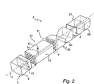
- FIG 2 illustrates, in an exploded view, the modular plastic fuel tank 2 of Figure 1 .
- Each of the bowl shaped modules 3, 13, 23, 33 respectively has a bowl end 4, an open end 5, and a space for accommodating fuel.
- the first three modules 3, 13, 23 are arranged to overlap one another in a longitudinal direction L, with the open end 5 of one module overlapping the bowl end 4 of another.
- the module closing the tank 2, i.e. the bowl shaped end module 33 is arranged with its open end 5 overlapping the open end 5 of the preceding module 23, i.e. the last intermediate module 23.
- the bowl ends 4 of the modules 3, 13, 23 contribute to the robustness of the tank 2, i.e. serve to reinforce the tank 2, to better meet the harsh automotive requirements of a heavy vehicle 1, such as vibrations, and reducing deformation of the tank 2 as it is fixed to the vehicle by means of for instance tank brackets and mounting straps.
- the open end 5 and bowl end 4 of the front module 3 and intermediate modules 13, 23 have matching cross sections, as shown in Figure 2 , thereby enabling for the open end 5 of any of the modules 3, 13, 23 to fit with the bowl end 4 of any other module 3, 13, 23.
- a module 3, 13, 23 can thus regardless of its shape between its two overlapping sections 6 overlap any other module 3, 13, 23 having a different shape between its two overlapping sections 6.
- the end module 33 preferably has its open end 5 matching the cross sections of the first three modules 3, 13, 23, such that the open end 5 of the end module 33 can fit with the open end 5 of any preceding module 3, 13, 23.
- the bowl ends 4 of the intermediate modules 13, 23 form baffle walls, improving the structural strength of the tank.
- the bowl ends are each provided with openings, thus enabling adjacent modules 13, 23 to be in communication with each other.
- the openings in the walls are formed to allow fuel to flow between the modules in limited volume, thus decreasing the impact of the fuel waves.
- Such wave-attenuating walls also referred to as “plash walls”, contribute to avoiding exhaustion of the plastic material.
- the length of the modules 3, 13, 23, 33 may vary, and so may their shapes compared to one another.
- one module 3, 13, 23, 33 may be circular in its longitudinal direction L while another may be D-shaped, should this combination be desirable.
- the modules 3, 13, 23, 33 have essentially rectangular cross sections, but the invention is not restricted thereto.
- a tank 2 in accordance with the invention has a varying cross section 8A, 8B along the longitudinal direction L so as to adapt the tank 2 to a heavy vehicle chassis. Consequently, the cross section 8A of one module may differ from a cross section 8B of another module.
- at least one of the modules 3, 13, 23, 33 has a varying cross section between its two overlapping sections 6 in the longitudinal direction L, and thus the third module, i.e. intermediate module 23, in Figure 2 has a varying cross section shape between its overlapping sections 6.
- the cross section shape of module 23 has been adapted to fit into the chassis shown in Figure 1 , where lack of space forces modifications to the shape of the tank 2 to avoid interference with for instance other vehicle mounted components.
- the minimum cross section 8A may typically be at least 10 percent smaller, and possibly more than 30 percent smaller than the maximum cross section 8B.
- Examples of component mounted to the frame requiring a reduction of the tank cross section include: spring anchorage (reduction about 5-10%), air tank bracket (25-35%), air tank (around 15%) and breather filter for fuel tank (5-10%).
- modules 3, 13, 23, 33 need to have a modified cross section depends on the chassis onto which the modular tank 2 is to be mounted.
- the adjustment of the cross section may include a varying module cross section diameter between the two overlapping sections of the specific module 3, 13, 23,33.
- module 3 comprises additional stiffening structures 12, preferably ribs, for reinforcement of the tank 2. If found necessary, however, the stiffening structures 12 may be comprised in all or a selection of the modules 3, 13, 23, 33.
- the tank 2 of Figure 2 comprises a filler neck 17, a fuel sender 14 and a drain plug 15. These are provided for the second module, i.e. intermediate module 13.
- the filler neck 17 allows fuel to be filled into the tank 2, the drain plug 15 fuel to be drained from the tank 2, and the fuel sender 15 the fuel level to be measured.
- the module 13 may comprise check valves for preventing fuel to flow in both directions, although not shown in this example. Which, if any, modules 3, 13, 23, 33 should comprise additional functional components 14, 15, 17 is for the designer of the tank 2 to judge.
- a plurality of bowl shaped modules 3, 13, 23, 33 are injection molded.
- injection molding is preferred, the invention is not restricted thereto.
- the modules 3, 13, 23, 33 may be formed using conventional techniques, such as for instance molding.
- the designer is able to form the modules more freely compared to what is possible with conventional techniques such as rotation- or blow-molding.
- a unique tool is designed for each unique module design. During production of the unique module 3, 13, 23 or 33, the corresponding tool is supplied with the plastic material of which the module is to be formed, and during heating of the plastic, the module is formed in accordance with the design of the tool.
- the bowl ends 4 of the intermediate modules 13, 23 are, during the injection molding of step 301, formed with openings, i.e. holes, through which fuel can flow.
- module 23 is formed with a varying cross section 8A in the longitudinal direction L of the module 23, between its overlapping sections 6.
- At least one of the modules is preferably an end module 33. If suitable for the tank 2 in which the end module 33 is to be comprised, the cross section of the end module 33 may likewise vary in the longitudinal direction L.
- At least one of the modules 3, 13, 23, 33 is further, during the injection molding of step 301, formed to have additional functional components, such as the components 14, 15, 17 mentioned above, or connections for mounting such components.
- At least one of the modules 3, 13, 23, 33 may optionally, as shown in step 305, further be provided with additional stiffening structures 12 for reinforcement of the tank 2, preferably ribs.
- the stiffening structures 12, which preferably are of plastic material or metal, are in the example of Figure 2 added to the front module 3 during the injection molding process, but alternatively, the stiffening structures 12 may likewise be provided to the module 3 afterwards.
- the front module 3 and the intermediate modules 13, 23 are, in step 306, connected to one another in the longitudinal direction L, with the open end 5 of one module 3, 13, 23 overlapping the bowl end 4 of another in the overlapping sections 6. Additionally, the end module 33 is arranged to with its open end 5 overlap the preceding module 23, attaching the two modules 23, 33 to one another.
- Two modules, in the example the intermediate modules 13, 23, may for instance be sealed by the use of glue or soldering, as shown in Figure 4A .
- the modules 13, 23 may be snap fitted to one another, as shown in Figures 4B to 4E .
- the two modules 13, 23 shown in Figure 4B each have a protrusion 18 and a recess 19.
- the recess 19 of one of the modules corresponds to the protrusion 18 of the other, and vice versa, thereby enabling snap fitting of the modules 13, 23 as they are assembled.
- Figure 4C shows another example of two modules 13, 23 snap fitted to one another, the recess 19 of one of the modules corresponding to the protrusion 18 of the other, and vice versa.
- the thickness of the tank wall is constant in the overlapping section 6.
- the snap fitting of the modules 13, 23 shown in Figure 4D is realized with an additional sealing element 16, such as an O-ring, inserted between the protrusion 18 and recess 19 of the modules 13, 23.
- the sealing element 16 is preferably, but not necessarily, inserted in the overlapping sections 6, in order to contribute to an improved attachment between the two modules 13, 23.
- FIG. 4E another example of snap fitting comprising an O-ring 16 is shown.
- the sealing element 16 is here arranged in a second recess 20 of one of the modules 23.
- the modules 13, 23 may be preheated prior to being fitted to one another. If found necessary, the modules may, in addition to being snap fitted, additionally be welded to one another to further contribute to keeping the modules fixed to one another.
- the overlapping sections 6 are in step 307 further covered with mounting straps applying an outer pressure, to even more improve the attachments of the modules 3, 13, 23, 33 to one another.
- the tank brackets and the mounting straps (not shown) for attaching the tank to the vehicle can be used for applying the outer pressure on the overlapping sections 6.
- a strap may additionally be wound around the modular tank 2 in the longitudinal direction L, in yet another effort to ensure that the modules 3, 13, 23, 33 are attached to one another.
Landscapes
- Engineering & Computer Science (AREA)
- Life Sciences & Earth Sciences (AREA)
- Sustainable Development (AREA)
- Sustainable Energy (AREA)
- Chemical & Material Sciences (AREA)
- Combustion & Propulsion (AREA)
- Transportation (AREA)
- Mechanical Engineering (AREA)
- Cooling, Air Intake And Gas Exhaust, And Fuel Tank Arrangements In Propulsion Units (AREA)
- Body Structure For Vehicles (AREA)
Claims (14)
- Modularer Kraftstofftank (2) für ein Schwerfahrzeug mit einer Vielzahl von schüsselförmigen Modulen (3, 13, 23), die ein offenes Ende (5) und ein Schüsselende (4) aufweisen, wobei die Module (3, 13, 23) in Längsrichtung (L) in einer Reihe miteinander verbunden sind, wobei das offene Ende eines Moduls (3, 13, 23) dem Schüsselende eines weiteren Moduls (3, 13, 23) zugewandt ist, wobei jedes der Module (3, 13, 23) einen Raum zur Aufnahme von Kraftstoff aufweist und die Räume mittels Löchern in den Schüsselenden (4) miteinander in Verbindung stehen, wobei der modulare Kraftstofftank (2) entlang der Längsrichtung (L) einen variierenden Außenquerschnitt aufweist, so dass der Tank bei Anbringung an einem Schwerfahrzeugrahmen an einen verfügbaren Raum angepasst ist,
dadurch gekennzeichnet, dass
das offene Ende (5) und das Schüsselende (4) jedes Moduls (3, 13, 23) zusammenpassende Querschnitte aufweisen, wodurch ermöglicht wird, dass ein offenes Ende (5) irgendeines Moduls (3, 13, 23) zu einem Schüsselende (4) irgendeines anderen Moduls (3, 13, 23) passt, und dass wenigstens eines der Module (3, 13, 23) einen minimalen Querschnitt (8A) aufweist, der um wenigstens zehn Prozent kleiner als ein maximaler Querschnitt (8B) eines anderen Moduls (3, 13, 23, 33) zwischen zusammenpassenden Querschnitten und entlang der Längsrichtung (L) ist, wobei die Querschnittsform (8A) so ausgelegt ist, dass sie die Querschnittsform des Moduls (23) in das Fahrgestell eines Fahrzeugs (1) hineinpasst. - Modularer Kraftstofftank nach Anspruch 1, wobei der Tank rotationssymmetrisch ist und einen variierenden Querschnittsdurchmesser entlang der Längsrichtung aufweist.
- Modularer Kraftstofftank nach irgendeinem der vorhergehenden Ansprüche, der weiterhin ein schüsselförmiges Endmodul (33) umfasst, das mit einem vorhergehenden Modul verbunden ist, wobei das offene Ende des Endmoduls dem offenen Ende des vorhergehenden Moduls zugewandt ist.
- Modularer Kraftstofftank nach irgendeinem der vorhergehenden Ansprüche, wobei jedes Modul aus Kunststoffmaterial gebildet ist.
- Modularer Kraftstofftank nach irgendeinem der vorhergehenden Ansprüche, wobei die Module mittels wenigstens einem aus Löten, einer Schnappverbindung, Schweißen, Schrauben oder Kleben aneinander befestigt sind.
- Modularer Kraftstofftank nach irgendeinem der vorhergehenden Ansprüche, wobei zumindest eines der Module weiterhin zusätzliche Versteifungsstrukturen (12) zur Verstärkung des Tanks umfasst.
- Verfahren zur Herstellung eines modularen Kraftstofftanks (2) für ein Schwerfahrzeug nach einem der vorhergehenden Ansprüche, das die Schritte umfasst:- Ausbilden einer Vielzahl von schüsselförmigen Modulen (3, 13, 23) mit einem offenen Ende (5) und einem Schüsselende (4), wobei die Schüsselenden (4) Löcher aufweisen, und- Verbinden (306) der Module (3, 13, 23) miteinander in einer Reihe in Längsrichtung (L), wobei das offene Ende (5) eines Moduls (3, 13, 23) dem Schüsselende (4) eines weiteren Moduls (3, 13, 23) zugewandt ist, wobei jedes der Module (3, 13, 23) einen Raum zur Aufnahme von Kraftstoff aufweist und die Räume mittels Löchern in den Schüsselenden (4) miteinander in Verbindung stehen,- wobei der Schritt des Ausbildens einer Vielzahl von schüsselförmigen Modulen (3, 13, 23) umfasst, dass die Module (3, 13, 23) derart ausgebildet werden, dass der Querschnitt des Tanks entlang der Längsrichtung (L) variiert, um den Tank (2) bei Anbringung an einem Schwerfahrzeugrahmen an einen verfügbaren Raum anzupassen,dadurch gekennzeichnet, dass- ein weiterer Schritt des Ausbildens wenigstens eines der Module (3, 13, 23) umfasst, dass ein offenes Ende (5) und ein Schüsselende (4) jedes Moduls (3, 13, 23) zusammenpassende Querschnitte aufweisen, wodurch ermöglicht wird, dass ein offenes Ende (5) irgendeines Moduls (3, 13, 23) zu einem Schüsselende (4) irgendeines anderen Moduls (3, 13, 23) passt, und dass eine minimale Querschnittsfläche (8A) wenigstens eines der Module (3, 13, 23) um wenigstens zehn Prozent kleiner als eine maximale Querschnittsfläche (8B) eines anderen Moduls (3, 13, 23, 33) zwischen zusammenpassenden Querschnitten und entlang der Längsrichtung (L) ist, um die Querschnittsform des Moduls (23) in das Fahrgestell eines Fahrzeugs (1) einzupassen.
- Verfahren nach Anspruch 7, wobei der Schritt des Ausbildens einer Vielzahl von schüsselförmigen Modulen das Formen (301) der Module umfasst.
- Verfahren nach Anspruch 8, wobei der Schritt des Ausbildens einer Vielzahl von schüsselförmigen Modulen das Spritzgießen (301) der Module umfasst.
- Verfahren nach irgendeinem der Ansprüche 7 bis 9, das weiterhin den Schritt des Verbindens eines schüsselförmigen Endmoduls mit einem vorhergehenden Modul umfasst, wobei das offene Ende des Endmoduls dem offenen Ende des vorhergehenden Moduls zugewandt ist.
- Verfahren nach irgendeinem der Ansprüche 7 bis 10, wobei für einen Tank mit Rotationssymmetrie der Tank einen variierenden Querschnittsdurchmesser entlang der Längsrichtung aufweist.
- Verfahren nach irgendeinem der Ansprüche 7 bis 11, wobei der Schritt des Verbindens der Module das Befestigen der Module aneinander mittels wenigstens einem aus Löten, einer Schnappverbindung, Schweißen, Schrauben oder Kleben aufweist.
- Verfahren nach irgendeinem der Ansprüche 7 bis 12, das weiterhin den Schritt aufweist, dass zusätzliche funktionelle Komponenten (14, 15, 17) oder Verbindungen für diese ausgebildet werden.
- Verfahren nach irgendeinem der Ansprüche 7 bis 13, das weiterhin den Schritt des Hinzufügens (305) von Versteifungsstrukturen zur Verstärkung des Tanks umfasst.
Applications Claiming Priority (1)
| Application Number | Priority Date | Filing Date | Title |
|---|---|---|---|
| PCT/SE2007/000907 WO2009051526A1 (en) | 2007-10-16 | 2007-10-16 | A modular fuel tank and a method of manufacturing a modular fuel tank |
Publications (3)
| Publication Number | Publication Date |
|---|---|
| EP2212145A1 EP2212145A1 (de) | 2010-08-04 |
| EP2212145A4 EP2212145A4 (de) | 2011-05-25 |
| EP2212145B1 true EP2212145B1 (de) | 2012-04-18 |
Family
ID=40567616
Family Applications (1)
| Application Number | Title | Priority Date | Filing Date |
|---|---|---|---|
| EP07835109A Not-in-force EP2212145B1 (de) | 2007-10-16 | 2007-10-16 | Modularer kraftstofftank und verfahren zur herstellung eines modularen kraftstofftanks |
Country Status (7)
| Country | Link |
|---|---|
| EP (1) | EP2212145B1 (de) |
| CN (1) | CN101883694A (de) |
| AT (1) | ATE553948T1 (de) |
| AU (1) | AU2007360193A1 (de) |
| BR (1) | BRPI0722154A2 (de) |
| WO (1) | WO2009051526A1 (de) |
| ZA (1) | ZA201002231B (de) |
Cited By (3)
| Publication number | Priority date | Publication date | Assignee | Title |
|---|---|---|---|---|
| WO2022053585A1 (en) * | 2020-09-09 | 2022-03-17 | Xcience Ltd | Pressure vessel liner, pressure vessel and methods |
| EP4394236A1 (de) * | 2023-01-02 | 2024-07-03 | Volvo Truck Corporation | Speichertank für ein fahrzeug zur lagerung von flüssigkeiten |
| US12392754B2 (en) | 2019-09-04 | 2025-08-19 | Soitec | Differential acoustic wave sensors |
Families Citing this family (3)
| Publication number | Priority date | Publication date | Assignee | Title |
|---|---|---|---|---|
| DE202011102744U1 (de) | 2011-06-10 | 2012-09-13 | Consolar Solare Energiesysteme Gmbh | Druckbelastbarer Segmentspeicher |
| SE539647C2 (sv) | 2014-04-15 | 2017-10-24 | Scania Cv Ab | Vändbar bränsletank, särskilt avsedd för fordon |
| DE102018101884A1 (de) * | 2018-01-29 | 2019-08-01 | Bayerische Motoren Werke Aktiengesellschaft | Modular aufgebauter Kunststoffbehälter |
Family Cites Families (9)
| Publication number | Priority date | Publication date | Assignee | Title |
|---|---|---|---|---|
| CA2114476A1 (en) * | 1993-07-09 | 1995-01-10 | Murray W. Mahoney | Conformable compressed gas storage tank |
| DE4442780C2 (de) * | 1994-12-01 | 1997-02-20 | Daimler Benz Aerospace Ag | Treibstofftank |
| FR2781431B1 (fr) * | 1998-07-21 | 2000-09-01 | Giat Ind Sa | Reservoir pour vehicule |
| MXPA01011157A (es) * | 1999-05-03 | 2003-08-01 | Alliant Techsystems Inc | Modulos de cierre terminal para recipientes a presion de varias celdas y recipientes a presion y vehiculos que contienen los mismos. |
| FR2795159B1 (fr) * | 1999-06-15 | 2001-08-10 | Liotard Metallurg | Reservoir resistant a la pression dont la forme s'adapte a la place dont on dispose pour le loger |
| CN2472044Y (zh) * | 2001-03-23 | 2002-01-16 | 何明亮 | 一种液化气钢瓶 |
| DE20306793U1 (de) * | 2003-04-30 | 2003-08-14 | Gebr. Dingerkus GmbH & Co. KG, 57439 Attendorn | Geschlossener Behälter für Flüssigkeiten oder Gase |
| DE10323072B4 (de) * | 2003-05-22 | 2006-07-20 | Daimlerchrysler Ag | Tankbehälter |
| SE529404C2 (sv) * | 2005-12-15 | 2007-07-31 | Volvo Lastvagnar Ab | Vätsketank och fastsättningsanordning för uppbärande av en vätsketank på en ram för ett tungt fordon |
-
2007
- 2007-10-16 EP EP07835109A patent/EP2212145B1/de not_active Not-in-force
- 2007-10-16 AU AU2007360193A patent/AU2007360193A1/en not_active Abandoned
- 2007-10-16 BR BRPI0722154-1A2A patent/BRPI0722154A2/pt not_active IP Right Cessation
- 2007-10-16 AT AT07835109T patent/ATE553948T1/de active
- 2007-10-16 WO PCT/SE2007/000907 patent/WO2009051526A1/en not_active Ceased
- 2007-10-16 CN CN2007801011374A patent/CN101883694A/zh active Pending
-
2010
- 2010-03-29 ZA ZA2010/02231A patent/ZA201002231B/en unknown
Cited By (3)
| Publication number | Priority date | Publication date | Assignee | Title |
|---|---|---|---|---|
| US12392754B2 (en) | 2019-09-04 | 2025-08-19 | Soitec | Differential acoustic wave sensors |
| WO2022053585A1 (en) * | 2020-09-09 | 2022-03-17 | Xcience Ltd | Pressure vessel liner, pressure vessel and methods |
| EP4394236A1 (de) * | 2023-01-02 | 2024-07-03 | Volvo Truck Corporation | Speichertank für ein fahrzeug zur lagerung von flüssigkeiten |
Also Published As
| Publication number | Publication date |
|---|---|
| CN101883694A (zh) | 2010-11-10 |
| BRPI0722154A2 (pt) | 2014-04-08 |
| ATE553948T1 (de) | 2012-05-15 |
| AU2007360193A1 (en) | 2009-04-23 |
| WO2009051526A1 (en) | 2009-04-23 |
| ZA201002231B (en) | 2010-12-29 |
| EP2212145A4 (de) | 2011-05-25 |
| EP2212145A1 (de) | 2010-08-04 |
Similar Documents
| Publication | Publication Date | Title |
|---|---|---|
| AU2007360193A1 (en) | A modular fuel tank and a method of manufacturing a modular fuel tank | |
| CN103129626B (zh) | 机动车车身的支承结构部件 | |
| US6921127B2 (en) | Structural part for a motor vehicle | |
| US8439591B2 (en) | Tube arrangement and crossbeam having such a tube arrangement | |
| ES2401605T3 (es) | Travesaño delantero de vehículo automóvil, soporte delantero y procedimiento de ensamblado | |
| CN103189266B (zh) | 轴梁,特别是机动车的前轴梁 | |
| US20100193275A1 (en) | Motorcycle | |
| JP2003500276A (ja) | サブフレーム | |
| US20090133762A1 (en) | Fuel tank | |
| CN101239627A (zh) | 汽车的前厢结构 | |
| US20090107565A1 (en) | Fuel Tank | |
| WO1996015010A1 (en) | Compartmentized plastic bumper | |
| CA2372336A1 (en) | Leak fuel gas discharging structure of automobile | |
| EP3385097B1 (de) | Stabilisatorverbindung für kraftfahrzeugaufhängungen | |
| KR20080069199A (ko) | 하이브리드 구조의 조립 지지체 | |
| DE50207294D1 (de) | Personenkraftwagen mit einem zwischen den fahrzeug-sitzen angeordneten kraftstoff-tank | |
| CN102498020A (zh) | 特别是用于液压式车辆制动系统的容器 | |
| CN201665248U (zh) | 底盘构件 | |
| JP4239773B2 (ja) | 自動車の後部荷室構造 | |
| US10981615B2 (en) | Fuel tank arrangement with at least two separate tank bodies | |
| US20150291021A1 (en) | Fuel supplying system | |
| CN203892074U (zh) | 车载加油油气回收系统及包含该系统的汽车 | |
| US20160361996A1 (en) | Liquid tank including integrated surface structure | |
| US8276928B2 (en) | Console for attachment to a vehicle chassis and vehicle comprising a suspension carrying console | |
| JP5171285B2 (ja) | 車体前部構造 |
Legal Events
| Date | Code | Title | Description |
|---|---|---|---|
| PUAI | Public reference made under article 153(3) epc to a published international application that has entered the european phase |
Free format text: ORIGINAL CODE: 0009012 |
|
| 17P | Request for examination filed |
Effective date: 20100517 |
|
| AK | Designated contracting states |
Kind code of ref document: A1 Designated state(s): AT BE BG CH CY CZ DE DK EE ES FI FR GB GR HU IE IS IT LI LT LU LV MC MT NL PL PT RO SE SI SK TR |
|
| AX | Request for extension of the european patent |
Extension state: AL BA HR MK RS |
|
| DAX | Request for extension of the european patent (deleted) | ||
| A4 | Supplementary search report drawn up and despatched |
Effective date: 20110429 |
|
| RIC1 | Information provided on ipc code assigned before grant |
Ipc: B60K 15/063 20060101ALI20110421BHEP Ipc: B60K 15/073 20060101AFI20090508BHEP Ipc: B60K 15/03 20060101ALI20110421BHEP |
|
| GRAP | Despatch of communication of intention to grant a patent |
Free format text: ORIGINAL CODE: EPIDOSNIGR1 |
|
| RIC1 | Information provided on ipc code assigned before grant |
Ipc: B60K 15/063 20060101ALI20111128BHEP Ipc: B60K 15/03 20060101ALI20111128BHEP Ipc: B60K 15/073 20060101AFI20111128BHEP |
|
| GRAS | Grant fee paid |
Free format text: ORIGINAL CODE: EPIDOSNIGR3 |
|
| GRAA | (expected) grant |
Free format text: ORIGINAL CODE: 0009210 |
|
| AK | Designated contracting states |
Kind code of ref document: B1 Designated state(s): AT BE BG CH CY CZ DE DK EE ES FI FR GB GR HU IE IS IT LI LT LU LV MC MT NL PL PT RO SE SI SK TR |
|
| REG | Reference to a national code |
Ref country code: GB Ref legal event code: FG4D |
|
| REG | Reference to a national code |
Ref country code: CH Ref legal event code: EP |
|
| REG | Reference to a national code |
Ref country code: IE Ref legal event code: FG4D |
|
| REG | Reference to a national code |
Ref country code: AT Ref legal event code: REF Ref document number: 553948 Country of ref document: AT Kind code of ref document: T Effective date: 20120515 |
|
| REG | Reference to a national code |
Ref country code: DE Ref legal event code: R096 Ref document number: 602007022150 Country of ref document: DE Effective date: 20120614 |
|
| REG | Reference to a national code |
Ref country code: NL Ref legal event code: VDEP Effective date: 20120418 |
|
| REG | Reference to a national code |
Ref country code: AT Ref legal event code: MK05 Ref document number: 553948 Country of ref document: AT Kind code of ref document: T Effective date: 20120418 |
|
| LTIE | Lt: invalidation of european patent or patent extension |
Effective date: 20120418 |
|
| PG25 | Lapsed in a contracting state [announced via postgrant information from national office to epo] |
Ref country code: SE Free format text: LAPSE BECAUSE OF FAILURE TO SUBMIT A TRANSLATION OF THE DESCRIPTION OR TO PAY THE FEE WITHIN THE PRESCRIBED TIME-LIMIT Effective date: 20120418 Ref country code: LT Free format text: LAPSE BECAUSE OF FAILURE TO SUBMIT A TRANSLATION OF THE DESCRIPTION OR TO PAY THE FEE WITHIN THE PRESCRIBED TIME-LIMIT Effective date: 20120418 Ref country code: IS Free format text: LAPSE BECAUSE OF FAILURE TO SUBMIT A TRANSLATION OF THE DESCRIPTION OR TO PAY THE FEE WITHIN THE PRESCRIBED TIME-LIMIT Effective date: 20120818 Ref country code: PL Free format text: LAPSE BECAUSE OF FAILURE TO SUBMIT A TRANSLATION OF THE DESCRIPTION OR TO PAY THE FEE WITHIN THE PRESCRIBED TIME-LIMIT Effective date: 20120418 Ref country code: FI Free format text: LAPSE BECAUSE OF FAILURE TO SUBMIT A TRANSLATION OF THE DESCRIPTION OR TO PAY THE FEE WITHIN THE PRESCRIBED TIME-LIMIT Effective date: 20120418 Ref country code: CY Free format text: LAPSE BECAUSE OF FAILURE TO SUBMIT A TRANSLATION OF THE DESCRIPTION OR TO PAY THE FEE WITHIN THE PRESCRIBED TIME-LIMIT Effective date: 20120418 |
|
| PG25 | Lapsed in a contracting state [announced via postgrant information from national office to epo] |
Ref country code: GR Free format text: LAPSE BECAUSE OF FAILURE TO SUBMIT A TRANSLATION OF THE DESCRIPTION OR TO PAY THE FEE WITHIN THE PRESCRIBED TIME-LIMIT Effective date: 20120719 Ref country code: SI Free format text: LAPSE BECAUSE OF FAILURE TO SUBMIT A TRANSLATION OF THE DESCRIPTION OR TO PAY THE FEE WITHIN THE PRESCRIBED TIME-LIMIT Effective date: 20120418 Ref country code: PT Free format text: LAPSE BECAUSE OF FAILURE TO SUBMIT A TRANSLATION OF THE DESCRIPTION OR TO PAY THE FEE WITHIN THE PRESCRIBED TIME-LIMIT Effective date: 20120820 Ref country code: LV Free format text: LAPSE BECAUSE OF FAILURE TO SUBMIT A TRANSLATION OF THE DESCRIPTION OR TO PAY THE FEE WITHIN THE PRESCRIBED TIME-LIMIT Effective date: 20120418 |
|
| PG25 | Lapsed in a contracting state [announced via postgrant information from national office to epo] |
Ref country code: BE Free format text: LAPSE BECAUSE OF FAILURE TO SUBMIT A TRANSLATION OF THE DESCRIPTION OR TO PAY THE FEE WITHIN THE PRESCRIBED TIME-LIMIT Effective date: 20120418 |
|
| PG25 | Lapsed in a contracting state [announced via postgrant information from national office to epo] |
Ref country code: AT Free format text: LAPSE BECAUSE OF FAILURE TO SUBMIT A TRANSLATION OF THE DESCRIPTION OR TO PAY THE FEE WITHIN THE PRESCRIBED TIME-LIMIT Effective date: 20120418 Ref country code: EE Free format text: LAPSE BECAUSE OF FAILURE TO SUBMIT A TRANSLATION OF THE DESCRIPTION OR TO PAY THE FEE WITHIN THE PRESCRIBED TIME-LIMIT Effective date: 20120418 Ref country code: SK Free format text: LAPSE BECAUSE OF FAILURE TO SUBMIT A TRANSLATION OF THE DESCRIPTION OR TO PAY THE FEE WITHIN THE PRESCRIBED TIME-LIMIT Effective date: 20120418 Ref country code: RO Free format text: LAPSE BECAUSE OF FAILURE TO SUBMIT A TRANSLATION OF THE DESCRIPTION OR TO PAY THE FEE WITHIN THE PRESCRIBED TIME-LIMIT Effective date: 20120418 Ref country code: DK Free format text: LAPSE BECAUSE OF FAILURE TO SUBMIT A TRANSLATION OF THE DESCRIPTION OR TO PAY THE FEE WITHIN THE PRESCRIBED TIME-LIMIT Effective date: 20120418 Ref country code: NL Free format text: LAPSE BECAUSE OF FAILURE TO SUBMIT A TRANSLATION OF THE DESCRIPTION OR TO PAY THE FEE WITHIN THE PRESCRIBED TIME-LIMIT Effective date: 20120418 Ref country code: CZ Free format text: LAPSE BECAUSE OF FAILURE TO SUBMIT A TRANSLATION OF THE DESCRIPTION OR TO PAY THE FEE WITHIN THE PRESCRIBED TIME-LIMIT Effective date: 20120418 |
|
| PLBE | No opposition filed within time limit |
Free format text: ORIGINAL CODE: 0009261 |
|
| STAA | Information on the status of an ep patent application or granted ep patent |
Free format text: STATUS: NO OPPOSITION FILED WITHIN TIME LIMIT |
|
| PG25 | Lapsed in a contracting state [announced via postgrant information from national office to epo] |
Ref country code: IT Free format text: LAPSE BECAUSE OF FAILURE TO SUBMIT A TRANSLATION OF THE DESCRIPTION OR TO PAY THE FEE WITHIN THE PRESCRIBED TIME-LIMIT Effective date: 20120418 |
|
| 26N | No opposition filed |
Effective date: 20130121 |
|
| PG25 | Lapsed in a contracting state [announced via postgrant information from national office to epo] |
Ref country code: ES Free format text: LAPSE BECAUSE OF FAILURE TO SUBMIT A TRANSLATION OF THE DESCRIPTION OR TO PAY THE FEE WITHIN THE PRESCRIBED TIME-LIMIT Effective date: 20120729 |
|
| REG | Reference to a national code |
Ref country code: DE Ref legal event code: R097 Ref document number: 602007022150 Country of ref document: DE Effective date: 20130121 |
|
| PG25 | Lapsed in a contracting state [announced via postgrant information from national office to epo] |
Ref country code: MC Free format text: LAPSE BECAUSE OF NON-PAYMENT OF DUE FEES Effective date: 20121031 |
|
| REG | Reference to a national code |
Ref country code: CH Ref legal event code: PL |
|
| GBPC | Gb: european patent ceased through non-payment of renewal fee |
Effective date: 20121016 |
|
| REG | Reference to a national code |
Ref country code: IE Ref legal event code: MM4A |
|
| REG | Reference to a national code |
Ref country code: FR Ref legal event code: ST Effective date: 20130628 |
|
| PG25 | Lapsed in a contracting state [announced via postgrant information from national office to epo] |
Ref country code: LI Free format text: LAPSE BECAUSE OF NON-PAYMENT OF DUE FEES Effective date: 20121031 Ref country code: CH Free format text: LAPSE BECAUSE OF NON-PAYMENT OF DUE FEES Effective date: 20121031 Ref country code: GB Free format text: LAPSE BECAUSE OF NON-PAYMENT OF DUE FEES Effective date: 20121016 Ref country code: BG Free format text: LAPSE BECAUSE OF FAILURE TO SUBMIT A TRANSLATION OF THE DESCRIPTION OR TO PAY THE FEE WITHIN THE PRESCRIBED TIME-LIMIT Effective date: 20120718 Ref country code: IE Free format text: LAPSE BECAUSE OF NON-PAYMENT OF DUE FEES Effective date: 20121016 |
|
| PG25 | Lapsed in a contracting state [announced via postgrant information from national office to epo] |
Ref country code: FR Free format text: LAPSE BECAUSE OF NON-PAYMENT OF DUE FEES Effective date: 20121031 |
|
| PG25 | Lapsed in a contracting state [announced via postgrant information from national office to epo] |
Ref country code: MT Free format text: LAPSE BECAUSE OF FAILURE TO SUBMIT A TRANSLATION OF THE DESCRIPTION OR TO PAY THE FEE WITHIN THE PRESCRIBED TIME-LIMIT Effective date: 20120418 |
|
| PG25 | Lapsed in a contracting state [announced via postgrant information from national office to epo] |
Ref country code: TR Free format text: LAPSE BECAUSE OF FAILURE TO SUBMIT A TRANSLATION OF THE DESCRIPTION OR TO PAY THE FEE WITHIN THE PRESCRIBED TIME-LIMIT Effective date: 20120418 |
|
| PG25 | Lapsed in a contracting state [announced via postgrant information from national office to epo] |
Ref country code: LU Free format text: LAPSE BECAUSE OF NON-PAYMENT OF DUE FEES Effective date: 20121016 |
|
| PG25 | Lapsed in a contracting state [announced via postgrant information from national office to epo] |
Ref country code: HU Free format text: LAPSE BECAUSE OF FAILURE TO SUBMIT A TRANSLATION OF THE DESCRIPTION OR TO PAY THE FEE WITHIN THE PRESCRIBED TIME-LIMIT Effective date: 20071016 |
|
| PGFP | Annual fee paid to national office [announced via postgrant information from national office to epo] |
Ref country code: DE Payment date: 20151013 Year of fee payment: 9 |
|
| REG | Reference to a national code |
Ref country code: DE Ref legal event code: R119 Ref document number: 602007022150 Country of ref document: DE |
|
| PG25 | Lapsed in a contracting state [announced via postgrant information from national office to epo] |
Ref country code: DE Free format text: LAPSE BECAUSE OF NON-PAYMENT OF DUE FEES Effective date: 20170503 |