EP2214337A2 - Selektiver Wellenlängen-Add/Drop-Multiplexer - Google Patents
Selektiver Wellenlängen-Add/Drop-Multiplexer Download PDFInfo
- Publication number
- EP2214337A2 EP2214337A2 EP10005130A EP10005130A EP2214337A2 EP 2214337 A2 EP2214337 A2 EP 2214337A2 EP 10005130 A EP10005130 A EP 10005130A EP 10005130 A EP10005130 A EP 10005130A EP 2214337 A2 EP2214337 A2 EP 2214337A2
- Authority
- EP
- European Patent Office
- Prior art keywords
- spectral component
- optical
- switches
- spectral
- switch
- Prior art date
- Legal status (The legal status is an assumption and is not a legal conclusion. Google has not performed a legal analysis and makes no representation as to the accuracy of the status listed.)
- Withdrawn
Links
- 230000003595 spectral effect Effects 0.000 claims abstract description 196
- 230000003287 optical effect Effects 0.000 claims abstract description 139
- 238000002310 reflectometry Methods 0.000 claims description 25
- 238000001914 filtration Methods 0.000 description 26
- 239000000835 fiber Substances 0.000 description 23
- 230000005540 biological transmission Effects 0.000 description 11
- 230000033001 locomotion Effects 0.000 description 10
- 238000003384 imaging method Methods 0.000 description 5
- 239000011248 coating agent Substances 0.000 description 4
- 238000000576 coating method Methods 0.000 description 4
- 239000000470 constituent Substances 0.000 description 3
- 239000013307 optical fiber Substances 0.000 description 3
- 230000000694 effects Effects 0.000 description 2
- 238000012545 processing Methods 0.000 description 2
- 238000013461 design Methods 0.000 description 1
- 238000006073 displacement reaction Methods 0.000 description 1
- 238000010348 incorporation Methods 0.000 description 1
- 238000002347 injection Methods 0.000 description 1
- 239000007924 injection Substances 0.000 description 1
- 238000003780 insertion Methods 0.000 description 1
- 230000037431 insertion Effects 0.000 description 1
- 238000012986 modification Methods 0.000 description 1
- 230000004048 modification Effects 0.000 description 1
- 230000010287 polarization Effects 0.000 description 1
- 230000000717 retained effect Effects 0.000 description 1
- 230000008054 signal transmission Effects 0.000 description 1
- 239000010409 thin film Substances 0.000 description 1
- 230000001131 transforming effect Effects 0.000 description 1
Images


Classifications
-
- G—PHYSICS
- G02—OPTICS
- G02B—OPTICAL ELEMENTS, SYSTEMS OR APPARATUS
- G02B6/00—Light guides; Structural details of arrangements comprising light guides and other optical elements, e.g. couplings
- G02B6/24—Coupling light guides
- G02B6/26—Optical coupling means
- G02B6/28—Optical coupling means having data bus means, i.e. plural waveguides interconnected and providing an inherently bidirectional system by mixing and splitting signals
- G02B6/293—Optical coupling means having data bus means, i.e. plural waveguides interconnected and providing an inherently bidirectional system by mixing and splitting signals with wavelength selective means
- G02B6/29379—Optical coupling means having data bus means, i.e. plural waveguides interconnected and providing an inherently bidirectional system by mixing and splitting signals with wavelength selective means characterised by the function or use of the complete device
- G02B6/2938—Optical coupling means having data bus means, i.e. plural waveguides interconnected and providing an inherently bidirectional system by mixing and splitting signals with wavelength selective means characterised by the function or use of the complete device for multiplexing or demultiplexing, i.e. combining or separating wavelengths, e.g. 1xN, NxM
- G02B6/29382—Optical coupling means having data bus means, i.e. plural waveguides interconnected and providing an inherently bidirectional system by mixing and splitting signals with wavelength selective means characterised by the function or use of the complete device for multiplexing or demultiplexing, i.e. combining or separating wavelengths, e.g. 1xN, NxM including at least adding or dropping a signal, i.e. passing the majority of signals
- G02B6/29383—Adding and dropping
-
- G—PHYSICS
- G02—OPTICS
- G02B—OPTICAL ELEMENTS, SYSTEMS OR APPARATUS
- G02B6/00—Light guides; Structural details of arrangements comprising light guides and other optical elements, e.g. couplings
- G02B6/24—Coupling light guides
- G02B6/26—Optical coupling means
- G02B6/28—Optical coupling means having data bus means, i.e. plural waveguides interconnected and providing an inherently bidirectional system by mixing and splitting signals
- G02B6/293—Optical coupling means having data bus means, i.e. plural waveguides interconnected and providing an inherently bidirectional system by mixing and splitting signals with wavelength selective means
- G02B6/29304—Optical coupling means having data bus means, i.e. plural waveguides interconnected and providing an inherently bidirectional system by mixing and splitting signals with wavelength selective means operating by diffraction, e.g. grating
- G02B6/29316—Light guides comprising a diffractive element, e.g. grating in or on the light guide such that diffracted light is confined in the light guide
- G02B6/29317—Light guides of the optical fibre type
-
- G—PHYSICS
- G02—OPTICS
- G02B—OPTICAL ELEMENTS, SYSTEMS OR APPARATUS
- G02B6/00—Light guides; Structural details of arrangements comprising light guides and other optical elements, e.g. couplings
- G02B6/24—Coupling light guides
- G02B6/26—Optical coupling means
- G02B6/28—Optical coupling means having data bus means, i.e. plural waveguides interconnected and providing an inherently bidirectional system by mixing and splitting signals
- G02B6/293—Optical coupling means having data bus means, i.e. plural waveguides interconnected and providing an inherently bidirectional system by mixing and splitting signals with wavelength selective means
- G02B6/29379—Optical coupling means having data bus means, i.e. plural waveguides interconnected and providing an inherently bidirectional system by mixing and splitting signals with wavelength selective means characterised by the function or use of the complete device
- G02B6/29395—Optical coupling means having data bus means, i.e. plural waveguides interconnected and providing an inherently bidirectional system by mixing and splitting signals with wavelength selective means characterised by the function or use of the complete device configurable, e.g. tunable or reconfigurable
-
- H—ELECTRICITY
- H04—ELECTRIC COMMUNICATION TECHNIQUE
- H04J—MULTIPLEX COMMUNICATION
- H04J14/00—Optical multiplex systems
- H04J14/02—Wavelength-division multiplex systems
- H04J14/0201—Add-and-drop multiplexing
- H04J14/0202—Arrangements therefor
- H04J14/0209—Multi-stage arrangements, e.g. by cascading multiplexers or demultiplexers
-
- H—ELECTRICITY
- H04—ELECTRIC COMMUNICATION TECHNIQUE
- H04J—MULTIPLEX COMMUNICATION
- H04J14/00—Optical multiplex systems
- H04J14/02—Wavelength-division multiplex systems
- H04J14/0201—Add-and-drop multiplexing
- H04J14/0202—Arrangements therefor
- H04J14/021—Reconfigurable arrangements, e.g. reconfigurable optical add/drop multiplexers [ROADM] or tunable optical add/drop multiplexers [TOADM]
- H04J14/0212—Reconfigurable arrangements, e.g. reconfigurable optical add/drop multiplexers [ROADM] or tunable optical add/drop multiplexers [TOADM] using optical switches or wavelength selective switches [WSS]
-
- H—ELECTRICITY
- H04—ELECTRIC COMMUNICATION TECHNIQUE
- H04J—MULTIPLEX COMMUNICATION
- H04J14/00—Optical multiplex systems
- H04J14/02—Wavelength-division multiplex systems
- H04J14/0201—Add-and-drop multiplexing
- H04J14/0215—Architecture aspects
- H04J14/0216—Bidirectional architectures
-
- H—ELECTRICITY
- H04—ELECTRIC COMMUNICATION TECHNIQUE
- H04Q—SELECTING
- H04Q11/00—Selecting arrangements for multiplex systems
- H04Q11/0001—Selecting arrangements for multiplex systems using optical switching
-
- H—ELECTRICITY
- H04—ELECTRIC COMMUNICATION TECHNIQUE
- H04J—MULTIPLEX COMMUNICATION
- H04J14/00—Optical multiplex systems
- H04J14/02—Wavelength-division multiplex systems
- H04J14/0201—Add-and-drop multiplexing
- H04J14/0215—Architecture aspects
- H04J14/0219—Modular or upgradable architectures
Definitions
- the present invention relates generally to optical communications networks. More particularly, the present invention relates to an article for adding spectral components to, and dropping spectral components from, a multiplexed optical signal.
- Wavelength-division-multiplexed (WDM) optical communications networks support multiplexed optical signals having many different spectral components or wavelengths. Each one of such wavelengths, referred to as a channel, represents an independent data stream.
- WDM Wavelength-division-multiplexed
- a wavelength-selective add-drop multiplexer (WSADM) is disclosed for adding and/or dropping spectral components from a wavelength-division-multiplexed optical signal.
- WSADM wavelength-selective add-drop multiplexer
- a (1x1) or (2x2) optical switche is used, either alone or in conjunction with other optical elements, to separate spectral components identified for drop from other spectral components, in accordance with the illustrative embodiments of the present invention..
- Each (1x1) switch comprises a micro-electromechanical actuator that positions a reflective device into, or out of, a path of a spectral component passing through the switch. It the reflective device is in the optical path, the spectral component is reflected therefrom, and does not cross the switch. If the reflective device is out of the optical path, the spectral component crosses the switch.
- Each (2x2) switch includes an optical director, which, in a first embodiment, is a variable-reflectivity device, such as an optical modulator, and in a second embodiment, is a constant reflectivity device that is actuated by a micro-electromechanical actuator.
- the WSADM in accordance with the illustrative embodiments of the present invention can be configured in a variety of ways as a function of switch selection, other among elements.
- the WSADM comprises, in principal part, one or two demultiplexer/multiplexers, such as a waveguide grating router, and the switches.
- the demultiplexer is used for separating a WDM signal into its constituent spectral components.
- the switches are used to suitably direct such spectral components for drop, or not, as desired.
- the separated spectral components are then run "backwards" through the waveguide grating router for re-multiplexing.
- (1x1) switches are used in the WSADM, and they must used in conjunction with optical circulators or the like. In other embodiments wherein (2x2) switches are used, such optical circulators are not required.
- a WSADM is configured as a cascade of (2x2) switches.
- the switches include a wavelength filtering device, such as a plurality of dielectric layers, which selectivity reflect or transmit various spectral components comprising the WDM signal.
- a wavelength filtering device such as a plurality of dielectric layers, which selectivity reflect or transmit various spectral components comprising the WDM signal.
- the illustrated embodiments of the present invention show a wavelength-selectable add-drop multiplexer (WSADM) for use in lightwave systems.
- WSADM wavelength-selectable add-drop multiplexer
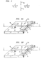
- FIG. 1 The functionality of a WSADM is illustrated in FIG. 1 .
- a WSADM receives WDM signal 2 having a multiplicity, N, of spectral components or wavelengths ⁇ 1 - ⁇ N .
- the N spectral components each of which is an independent data stream, define N "channels" of WDM signal 2.
- the WSADM is operable to remove or "drop" at least a first selected spectral component ⁇ 1 from the multiplicity of such spectral components.
- WSADM 1 is further operable to add at least a second selected spectral component ⁇ N+1 to the multiplicity of such spectral components.
- a first spectral component such as ⁇ 1
- a second spectral component such as ⁇ N+1
- the second selected spectral component is added to the channel from which the first selected spectral component is dropped.
- the added and dropped components have similar wavelengths, i.e., the wavelengths of both spectral components fall within the band or range of wavelengths defined for a given channel.
- the first dropped and second added spectral components will typically carry different information.
- a spectral component such as ⁇ N+1
- the spectral component ⁇ 1 occupying the channel to which ⁇ N+1 is added must be dropped to avoid interference between the two signals.
- a first spectral component may be dropped without adding a second spectral component to replace it, but a second spectral component may not be added without dropping a first spectral component otherwise occupying the same channel.
- Multiplexed signal 3 results from the add and drop operations discussed above, wherein, in the illustrative embodiment shown in FIG. 1 , the second selected spectral component ⁇ N+1 has replaced the first selected spectral component ⁇ 1 . It should be understood that one or more spectral components can be added or dropped by a WSADM according to the present invention.
- optical switches are used, at times in conjunction with other elements, to separate the one or more spectral components selected for "drop” from other spectral components, or to introduce the one or more spectral components selected for "add.”
- Switches suitable for use in conjunction with the present invention have low insertion loss (preferably less than 1 dB), high contrast ratio (preferably greater than 20/1), wide optical bandwidth (preferably at least about 30 nm around a center wavelength), moderate speed (at least about 1 mbit/sec), low cost and substantially no temperature or polarization dependence.
- Using such optical switches advantageously provides a low cost, robust, sufficiently fast and transmission format independent wavelength-selectable add-drop multiplexer.
- First switch S1 suitable for use in conjunction with the present invention is a (1x1) micro-machined optical switch, such as is described in U.S. Pat. App. 08/856569 filed May 15, 1997 .
- Illustrative embodiments of such a (1x1) switch use a micro-electromechanical systems (MEMS)-based actuator to move an optical device into, and out of, the path of an optical signal. If the optical device is in the path of the optical signal, it affects the signal in some manner.
- the optical device is a reflective device having a fixed reflectivity, such as a dielectric mirror or the like.
- the switch is in a substantially reflective state, and, if the reflective device is out of the optical path, the switch is in a substantially transmissive state.
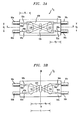
- FIG. 2a A simplified illustration of one embodiment of such a switch and its operation is shown in FIG. 2a .
- switch S1a is configured for "in-plane” switching.
- in-plane horizontal, “out-of-plane” and vertical reference a direction or location relative to the surface of a support upon which the optical switch resides.
- in-plane or horizontal movement refers to movement along a plane parallel to the surface of the support.
- Optical switch S1a includes hinged-plate actuator 4a, described in more detail later in this specification, reflective device 8, and linkage 6a.
- Optical switch S1a and two waveguides 12, 14 are disposed on support 16.
- Linkage 6a mechanically links or interconnects hinged-plate actuator 4a to reflective device 8.
- Linkage 6a is situated along axis 1-1 passing through gap 10 between waveguides 12 and 14.
- the two spaced waveguides 12, 14 are aligned to optically communicate.
- the waveguides may be optical fibers or other suitable optical transmission media.
- Linkage 6a and reflective device 8 are positioned relative to optical fibers 12, 14 so that the optical device is movable between a first position that is in the path of an optical signal traveling between the fibers placing the switch in a reflective state, and a second position that is out of the optical path placing the switch in a substantially transmissive state. Since, as described above, the actuator 4a imparts an in-plane motion to linkage 6a, optical device 8 moves horizontally back-and-forth, i.e., in a reciprocating-like motion, indicated by direction vector 18, moving into and out of the optical path. It should be appreciated that optical switch S1a can be configured so that reflective device 8 is at the first position (in the optical path) when actuator 4a is actuated, and at the second position (out of the optical path) when not actuated, or vice-versa.
- actuator 4a comprises two vertically-oriented electrodes. One of the electrodes is movable, the other of the electrodes is fixed. As a voltage is applied across the electrodes by a controlled voltage source, the movable electrode swings towards the fixed electrode. The substantially horizontal displacement of the movable electrode is transferred, by linkage 6a, to reflective device 8. As a result, reflective device 8 moves horizontally or "in-plane" along a path that places it in, or out of, the optical path as a function of the back and forth oscillatory-type motion of the movable electrode.
- switch S1b is configured for "out-of-plane" switching.
- Switch S1b includes actuator 4b configured to impart out-of-plane motion, indicated by direction vector 19, via linkage 6b to reflective device 8.
- Optical switch S1b and waveguides 12, 14 are disposed on support 16.
- Linkage 6b is situated along axis 1-1 passing through gap 10 between waveguides 12, 14.
- Linkage 6b and reflective device 8 are positioned relative to waveguides 12, 14 so that the optical device is movable between a first position that is in the path of an optical signal traveling between the waveguides placing the switch in a substantially reflective state, and a second position that is out of the optical path placing the switch in a substantially transmissive state. Since, as mentioned above, actuator 4b imparts a vertical or out-of-plane motion to linkage 6b, reflective device 8 therefore moves in a substantially "up-and-down" or vertically reciprocating motion into and out of the optical path.
- optical switch ) S1b can be configured so that the reflective device 8 is at the first position (in the optical path) when actuator 4b is actuated, and at the second position (out of the optical path) when not actuated, or vice-versa.
- actuator 4b includes at least one horizontally-disposed, vertically-movable electrode that is suspended over a conductive region of support 16. As a voltage is applied from a controlled voltage source across the electrode and conductive region, the vertically-movable electrode moves downwardly toward the conductive region.
- Linkage 6b which, in one embodiment, is a beam and pivot member configured in a teeter or seesaw fashion, transfers the vertical or out-of-plane oscillatory-type motion of the electrode to reflective device 8 positioned between the two waveguides.
- the reflecting means moves vertically into and out of an optical path of an optical signal traveling through the waveguides.
- the electrodes, linkages and other elements of optical switches S1a and S1b described above are implemented as hinged plates.
- hinged plates are well known to those skilled in micro mechanics. Further detail concerning hinged plates and a (1x1) micro-machined optical switch is provided in U.S. Pat. Apps. S.N. 08/856565 and S.N. 08/856569 , both of which are incorporated by reference herein.
- For additional background information concerning hinged plates see Pister et al., "Microfabricated Hinges,” v.33, Sensors and Actuators A, pp. 249-256, 1992 .
- a second switch suitable for use in conjunction with the present invention is a (2x2) free space optical bypass-exchange switch, such as is described in U.S. Pat. App. 08/912883 filed August 16, 1997 .
- Some embodiments of the (2x2) switch illustrated therein include telecentric imaging device 104 for delivering a signal from an input to an output with high efficiency, and further include optical director 106 capable of changing the path of an optical signal through the switch.
- optical director 106 is a variable-reflectivity device, such as an optical modulator, or a constant-reflectivity device, such as a dielectric mirror. If a variable reflectivity device is used, the switching function is obtained, i.e., the path of an optical signal traveling therethrough is changed, by a controlled change in reflectivity, such as between substantially transmissive and substantially reflective. If a constant-reflectivity mirror is used, the switching function is obtained by moving the mirror into and out of the path of an optical signal traveling through the switch, again placing the switch in respective substantially reflective or transmissive states. Such movement is actuated, in some embodiments, by a MEMS-based actuator, such as actuators 4a, 4b described above.
- a MEMS-based actuator such as actuators 4a, 4b described above.
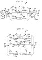
- FIGS. 3a and 3b An exemplary embodiment of the (2x2) free space optical bypass-exchange switch is shown in FIGS. 3a and 3b .
- telecentric imaging device 104 is a pair of lenses 110, 112 appropriate for collimating light incident thereon. Suitable lenses include, without limitation, graded index (GRIN) lenses, ball lenses and molded lenses, such as, for example, injection molded lenses. The functioning and location of such lenses 110, 112 for providing the desired telecentric optical system is described below.
- the optical director 106 is a variable-reflectivity device, and inputs 90a, 90c and outputs 90b and 90d are implemented as optical fibers.
- FIG. 3a illustrates a cross or "exchange” or “substantially transmissive” state wherein optical signal 92 (ray trace 92a) is imaged from first input fiber 90a into first output fiber 90b and optical signal 94 (ray trace 94a) is imaged from second input fiber 90c into second output fiber 90d.
- optical signal 92 ray trace 92a
- optical signal 94 ray trace 94a
- Such imaging is accomplished as follows.
- Collimating lens 110 is positioned at a distance d 1 from first input fiber 90a. If distance d 1 is equal to the focal length of collimating lens 110, the lens will collimate light incident thereon. Thus, with d 1 equal to the focal length of lens 110, the lens will collimate optical signal 92.
- Collimating lens 112 is positioned at a distance d 3 from second input fiber 90c. If the distance d 3 is equal to the focal length of lens 112, the lens will collimate optical signal 94. Since, as previously noted, the distance d
- optical signal 92 (ray trace 92a) is collimated by lens 110, remains collimated as received by lens 112, and is imaged into first output fiber 90b.
- the telecentric optical system is thus created by one pass through lens 110 and one pass through lens 112.
- the input fibers and output fibers 90a - 90d are equidistant from an optical axis A-A of lenses 110 and 112.
- Optical signal 94 (ray trace 94a) is collimated by lens 112, remains collimated as received by lens 110, and is imaged into second output fiber 90d.
- FIG. 3b A bar or "bypass” or “substantially reflective” state of the bypass-exchange switch is illustrated in FIG. 3b , wherein optical signal 92 (ray trace 92b) is imaged from first input fiber 90a into the second output fiber 90d, and optical signal 94 (ray trace 94b) is imaged from second input fiber 90c into first output fiber 90b.
- Signal 92 is imaged into second output fiber 90d at high efficiency by situating optical director 106 at the Fourier plane B-B, i.e., the back focal plane of collimating lens 110, at a distance d 5 from lens 110.
- a collimated beam entering a lens is focused to a point on a surface located at the Fourier plane. See , Goodman, Introduction to Physical Optics, Chapter 5, "Fourier Transforming and Imaging Properties of Lenses,” (MeGraw-Hill, 1968 ) for a mathematical definition.
- Optical director 106 is disposed distance d 6 from collimating lens 112, at the Fourier plane of lens 112, so that optical signal 94 is imaged into first output fiber 90b at high efficiency .
- d 5 is equal to d 6 , so that the Fourier plane B-B and optical director 106 are located equidistant from lenses 110 and 112.
- lenses 110, 112 are quarter-pitch GRIN lenses.
- a quarter-pitch GRIN lens is the shortest length GRIN lens that will substantially collimate an optical signal, such as optical signals 92 and 94.
- an optical signal such as optical signals 92 and 94.
- a suitably actuated constant-reflectivity device can be substituted for the variable-reflectivity device used in the illustrative embodiment shown in FIGS. 3a and 3b . Further detail concerning the above-described (2x2) free space optical bypass-exchange switch is provided in U.S. Pat. App. 08/912883 .
- Switch selection as well as other variations in the configuration of the present WSADM are addressed below by way of six illustrative embodiments shown in FIGS. 4-7 and 9-10 and described in the accompanying text.
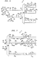
- FIG. 4 shows a first embodiment of WSADM 1a suitable for processing WDM signal 270 having N channels.
- WSADM 1a receives, as input, WDM signal 270 carried on waveguide 202.
- WDM signal 270 is received by port 222 of optical circulator 220.
- the operation of optical circulator 220 is such that an optical signal, such as WDM signal 270, is delivered to the next port along circulation direction 218, which is port 224. From port 224, signal 270 is launched along waveguide 204 towards a device suitable for separating or demultiplexing WDM signal 270 into its constituent spectral components 270 1 - 270 N .
- WGR waveguide grating router
- (1 x N) WGR 240 demultiplexes WDM signal 270 into its N spectral components.
- the N spectral components of WDM signal 270 appear on the outputs of WGR 240 and are carried by waveguides 206 1 - 206 N to (N) (1x1) switches S1 1 - S1 N .
- the (1x1) switches S1 1 - S1 N are configured as previously described.
- the subsequent path of each spectral component 270 1 - 270 N is controlled by the respective associated (1x1) switch S1 1 - S1 N . More particularly, the switches are placed in either of two states; a reflective state, in which substantially no light crosses the switch, and a transmissive state, in which substantially all light crosses the switch.
- a reflective device such as a dielectric mirror, is positioned in the optical path of the spectral component traveling through a switch.
- (1x1) switch S1 2 is shown in a substantially reflective state in FIG. 4 .
- reflective device 8 causes substantially all optical energy of spectral component 270 2 to be reflected back along waveguide 206 2 to WGR 240.
- Spectral component 270 2 passes through WGR 240 and emerges on waveguide 204, and is delivered to port 224 of optical circulator 220.
- Optical circulator 220 advances the spectral component to port 226 for "drop.” In this manner, one or more spectral components can be dropped from a WDM signal.
- the reflective device In the transmissive state, the reflective device is positioned out of the optical path of the spectral component traveling therethrough.
- spectral components entering switches that are in a substantially transmissive state such as switch S1 1
- waveguides such as waveguide 208 1
- Spectral components entering the WGR 250 are recombined or remultiplexed.
- Remultiplexed signal 272 appears at the output of WGR 250 and is launched into waveguide 209 and delivered to port 234 of second optical circulator 230.
- Optical circulator 230 delivers WDM signal 272 to port 236 and into waveguide 212 for transmission to a network node or the like.
- One or more spectral components can be added to the original group of spectral components 270 1 - 270 N comprising WDM signal 270 (less any dropped spectral components). Such addition is accomplished by delivering the spectral components to be added to port 232 of optical circulator 230. For clarity of description, the addition of only one spectral component 270 N+1 is described below. It should be understood, however, that the N (1x1) switches can add N spectral components, assuming a like number of spectral components are dropped from the original signal. The one additional spectral component 270 N+1 is advanced from port 232 to port 234 and launched into waveguide 210 towards the WGR 250.
- the WGR 250 delivers the spectral component onto the appropriate one of waveguides 208 1 - 208 N as a function of wavelength.
- Spectral component 270 N+1 is assumed to have a wavelength appropriate for occupying the channel vacated by dropped spectral component 270 2 . As such, spectral component 270 N+1 is launched into waveguide 208 2 and encounters switch S1 2 .
- spectral component 270 N+1 is likewise reflected upon entering the switch S1 2 , but towards WGR 250, there to be multiplexed along with other spectral components 270 1 and 270 3 - 270 N into WDM signal 272.
- FIG. 5 shows a second illustrative embodiment of a WSADM 1b.
- WSADM 1b a multiplicity of (N) (2x2) switches S2 1 - S2 N , such as those described previously in this specification, replace the (1x1) switches of the previous embodiment.
- (2x2) switches S2 1 - S2 N optical circulators 220, 230 used in conjunction with the (1x1) switches of the first illustrative embodiment are no longer required, as is described below.
- WSADM 1b receives, as input, WDM signal 270 carried on waveguide 202.
- WDM signal 270 is delivered to (1xN) WGR 240 wherein it is demultiplexed into its constituent spectral components 270 1 - 270 N .
- the N spectral components of WDM signal 270 appear on the outputs of WGR 240 and are carried by waveguides 206 1 - 206 N to N (2x2) switches S2 1 - S2 N .
- the (2x2) switches S2 1 - S2 N are configured as previously described, using, as the optical director 106, either a constant-reflectivity device and actuator, such as actuators 4a, 4b, or a variable-reflectivity device.
- the switches may be placed, on an individual basis, in a transmissive state, wherein optical director 106 is substantially "invisible" to a spectral component traveling therethrough.
- optical director 106 is a variable-reflectivity device
- the switch is placed in a transmissive state by placing the variable-reflectivity device into a low reflectivity state.
- optical director 106 is a constant-reflectivity device
- the switch is placed in a transmissive state by removing the constant-reflectivity device from the optical path via operation of an associated actuator.
- the switches may be placed, on an individual basis, in a reflective state, wherein optical director 106 reflects a substantial portion of a spectral component incident thereon.
- the switch is placed in a reflective state by placing the variable-reflectivity device into a high reflectivity state.
- the switch is placed in a reflective state by positioning the constant-reflectivity device in the optical path via operation of an associated actuator.
- each spectral component 270 1 - 270 N i.e., drop or remultiplexed into WDM signal 272, is controlled by respective associated (2x2) switch S2 1 - S2 N .
- the (2x2) switches have two inputs and two outputs.
- First input S2 i IN1 of each (2x2) switch receives one of spectral components 270 1 - 270 N delivered to it from one of waveguides 206 1 - 206 N . If the switch is in a transmissive state, the one spectral component crosses the switch and is coupled into first output S2 i OUT1 for delivery to WGR 250 along appropriate waveguide 208 1 - 208 N .
- switch S2 1 is in a transmissive state.
- Spectral component 270 1 delivered to input S2 1 IN1 of switch S2 1 via waveguide 206 1 crosses the switch, couples to output S2 1 OUT1 and is launched into waveguide 208 1 .
- spectral components, such as component 270 1 entering switches that are in a transmissive state, traverse such switches undisturbed and are launched into waveguides, such as waveguide 208 1 , leading to a second (1 x N) WGR 250.
- Spectral components entering the WGR 250 are recombined or remultiplexed therein.
- Remultiplexed signal 272 appears at the output of WGR 250 and is launched into waveguide 209 for transmission to a network node or the like.
- the switch is in a reflective state, the one spectral component received at input S2 i IN1 is coupled into second output S2 i OUT2 and launched into waveguide 210 i for drop.
- switch S2 2 is in a reflective state.
- Spectral component 270 2 delivered to S2 2 1N1 of the switch S2 2 via waveguide 206 2 encounters optical director 106.
- spectral component 270 2 is reflected towards, and coupled with high efficiency into, second output S2 2 OUT2 and launched into waveguide 210 2 for drop.
- second input S2 1 IN2 can be used for adding a spectral component to the WDM signal.
- the added spectral component is delivered to S2 1 IN2 via "add" waveguide 212i, is then coupled into first output S2 1i UT1 and launched into waveguide 208 i .
- spectral component 270 N+1 is added by delivering it to add waveguide 212 2 .
- spectral component 270 N+1 encounters optical director 106, it is reflected towards, and couples with high efficiency into, waveguide 208 2 .
- the spectral component is delivered to second WGR 250 and is multiplexed, along with spectral components 270 1 and 270 3 - 270 N , into WDM signal 272.
- WSADM 1c and 1d shown in respective FIGS. 6 and 7 are configured such that only a single multiplexing/demultiplexing device 340 is required.
- Demultiplexer/multiplexer 340 is a (1 x 2N) device having 1 ⁇ 2 free spectral range. There are two ports 342, 344 on the "multiplexed" side of the device.
- the multiplexer/demultiplexer is realized as a WGR.
- One port 342 of WGR 340 receives the WDM signal 270 from waveguide 204, and further receives any spectral components selected for drop that are leaving WGR 340, such as spectral component 270 2 .
- the other port 344 receives remultiplexed signal 272 leaving WGR 340, and further receives any spectral components selected for add from waveguide 210, such as spectral component 270 n+1 .
- WSADM 1c utilizes N (1x1) switches S1 1 - S1 N and two (1x N) optical circulators 220, 230.
- WSADM 1c receives, as input, WDM signal 270 carried on waveguide 202.
- WDM signal 270 is delivered to port 222 of optical circulator 220.
- WDM signal 270 is delivered to the next port along circulation direction 218, which is port 224.
- signal 270 is launched along waveguide 204 towards (2 x 2N) WGR 340.
- Demultiplexed spectral components 270 1 - 270 N appear on the outputs of WGR 340 and are carried by waveguides 206 1 - 206 N to (N) (1x1) switches S1 1 - S1 N .
- spectral component i.e., drop or remultiplex into a WDM signal
- (1x1) switch S1 2 is shown in a substantially reflective state that causes spectral component 270 2 to be reflected back along waveguide 206 2 to WGR 340.
- Spectral component 270 2 passes through WGR 340 and emerges on waveguide 204, which delivers that spectral component to port 224 of optical circulator 220.
- Optical circulator 220 advances the spectral component to port 226 for drop.
- Sitch S1 1 is shown in a transmissive state, wherein spectral component 270 1 crosses switch S1 1 undisturbed and is launched into waveguide 208 1 .
- Spectral component 270 1 and other spectral components crossing other switches S1 3 - S1 N are delivered to port 344 of WGR 340.
- WDM signal 272 is launched into waveguide 209 and delivered to port 234 of a second optical circulator 230.
- Optical circulator 230 delivers WDM signal 272 to port 236 and into waveguide 212 for transmission to a network node or the like.
- One or more spectral components can be added using WSADM 1c by delivering such spectral components to port 232 of optical circulator 230. Again, for clarity of description, the addition of only one spectral component 270 N+1 is described below.
- the one additional spectral component 270 N+1 is advanced from port 232 to port 234 and launched into waveguide 209 towards port 344 of WGR 340.
- the WGR 340 delivers the spectral component onto the appropriate one of waveguides 208 1 - 208 N as a function of wavelength.
- Spectral component 270 N+1 is assumed to have a wavelength appropriate for it to occupy the channel vacated by dropped spectral component 270 2 . As such, spectral component 270 N+1 is launched into waveguide 208 2 and encounters switch S1 2 .
- spectral component 270 N+1 is likewise reflected upon entering switch S1 2 , but along waveguide 208 2 , so that upon entering WGR 340, it is multiplexed along with other spectral components 270 1 and 270 3 - 270 N into WDM signal 272 and delivered to port 344.
- WDM signal 272 is launched into waveguide 209 and is received by port 234 of optical circulator 230.
- the optical circulator delivers signal 272 to port 236, at which point signal 272 is launched into waveguide 212 for transmission to a network node or the like.
- FIG. 7 shows a fourth illustrative embodiment of a WSADM 1d.
- WSADM 1d as in WSADM 1b, a multiplicity of (N) (2x2) switches S2 1 - S2 N replace the (1x1) switches.
- (2x2) switches S2 1 - S2 N optical circulators 220, 230 that were required for use in conjunction with the (1x1) switches are no longer needed.
- WSADM 1d receives, as input, WDM signal 270 carried on waveguide 202.
- WDM signal 270 is delivered to port 342 of (2 x 2N) WGR 340.
- the WGR 340 demultiplexes WDM signal 270.
- Demultiplexed spectral components 270 1 - 270 N appear on the outputs of WGR 340 and are carried by waveguides 206 1 - 206 N to (2x2) switches S1 1 - S1 N .
- placing a switch, such as switch S2 2 in a substantially transmissive state causes spectral component drop and add.
- spectral component 270 2 is coupled to first output S2 2 OUT1 and launched into waveguide 210 2 for drop.
- Spectral component 270 N+1 is added by delivering it the second input S2 2 IN2 via waveguide 212 2 .
- Spectral component 270 N+1 is coupled to second output S2 2 OUT2 , launched into waveguide 208 2 and delivered thereby to WGR 340.
- Spectral component 270 N+1 is multiplexed, along with spectral components that have not been dropped, into WDM signal 272, delivered to port 344 and launched into waveguide 209 for transmission to a network node or the like.
- Spectral components such as spectral component 212 1 , that are delivered to first input S2 i IN1 of switches that are in a reflective state, such as switch S2 1 , are coupled to output S2 1 OUT2 on contact with optical director 106. Such spectral components are then delivered, via waveguide 208 1 , to WGR 340. Those spectral components are multiplexed in WGR 340 into WDM signal 272 and delivered to output 344. WDM signal 272 is launched into waveguide 209 for transmission to a network node or the like.
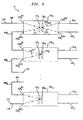
- FIGS. 9 and 10 show two additional exemplary embodiments of a WSADM.
- the demultiplexing/multiplexing device that was used in the previously-described embodiments e.g., the WGR
- the WGR is not required.
- a plurality of wavelength "filtering" devices such as may be realized, for example, by thin film transmission filters or fiber Bragg gratings, are used for adding and dropping spectral components from a WDM signal, as required.
- wavelength filtering device 107 is a dielectric surface coating disposed on an end of a lens.
- two grin lenses are used to create telecentric imaging device 104 ( FIGS. 3A & 3B ).
- a dielectric surface coating can be disposed on an end of one of such grin lenses.
- the dielectric surface coating which comprises a plurality of dielectric layers having different indices of refraction, is operable to reflect a preselected group of spectral components, and to transmit other spectral components. Forming such a surface coating to reflect a given group of spectral components, and to transmit others, is within the capabilities of those skilled in the art.
- WDM signal 270 is received at input S2A i IN1 and directed toward wavelength filtering device 107.
- wavelength filtering device 107 is operable, by design, to reflect spectral components 270 2 - 270 N .
- those spectral components are reflected toward the output S2A i OUT2 , while spectral component 270 1 is transmitted through the wavelength filtering device.
- switch S2A 1 is in a transmissive state, so that spectral component 270 1 is transmitted through optical director 106 and is coupled into output S2A i OUT1 for drop.
- FIG. 8a switch S2A 1 is in a transmissive state, so that spectral component 270 1 is transmitted through optical director 106 and is coupled into output S2A i OUT1 for drop.
- spectral component 270 N+1 is added to the retained group of spectral components, forming WDM signal 272.
- Spectral components 270 1 and 270 N+1 have substantially similar wavelengths, so that spectral component 270 N+1 will not be reflected upon contact with wavelength filtering device 107, but rather pass through it as did spectral component 270 1 .
- switch S2A 1 is shown in a reflective state, so that after passing through wavelength filtering device 107, spectral component 270 1 is reflected by optical director 106, passes again through wavelength filtering device 107, and rejoins spectral components 270 2 - 270 N .
- wavelength filtering device 107 always reflects spectral components having particular wavelengths, and transmits spectral components having other wavelengths, the "drop" of spectral components having the other wavelengths is controllable as a function of the state of the switch.
- wavelength filtering device 107 reflects a major portion of spectral components, i.e., 270 2 - 270 N , of WDM signal 270, transmitting just one spectral component 270 1 .
- FIG. 8c shows an alternate embodiment, wherein wavelength filtering device 107 is operable to reflect a single spectral component, e.g., 270 1 , toward S2A 1 OUT2 , and transmit the balance of the spectral components 270 2 - 270 N to output S2A i OUT1 .
- Spectral component 270 N+1 is added by delivering it to input S2A i IN2 , from where it is directed towards, and passes through, optical director 106.
- Spectral component 270 N+1 encounters wavelength filtering device 107, and is reflected thereby towards output S2A i OUT1 . Note that in the embodiment pictured in FIG. 8c , the switch is maintained in a transmissive state, and the filtered spectral component is always dropped.
- WSADM 1e comprises a cascade of N waveguide-coupled (2x2) switches S2A 1 - S2A N .
- the (2x2) switches are configured as shown in FIGS. 8a & 8b . It should be understood that in other embodiments, the switches can be configured as shown in FIG. 8c .
- WDM signal 270 is delivered to input S2A 1 IN1 of switch S2A 1 via waveguide 402.
- WDM signal 270 is directed toward wavelength filtering device 107 1 , and, upon contact with that wavelength filtering device, spectral components 270 2 - 270 N of WDM signal 270 are reflected towards output S2A 1 OUT2 .
- Spectral component 270 1 is transmitted through wavelength filtering device 107 1 , and, since switch S2A 1 is in a transmissive state, further passes through optical director 106 1 and is coupled to output S2A 1 OUT1 .
- Spectral component 270 N+1 is delivered to input S2A 1 IN1 for add via waveguide 404 1 .
- Spectral component 270 N+1 is coupled to output S2A 1 OUT2 , passing through optical director 106 1 and wavelength filtering device 107 1 .
- WDM signal 271 comprising spectral components coupled to output S2A 1 OUT2 , is launched into waveguide 408, and delivered to input S2A 2 IN1 of switch S2A 2 . Since switch S2A 2 is in a reflective state, all spectral components are reflected towards output S2A 2 OUT2 , including spectral component 270 2 , which passes through wavelength filtering device 107 2.
- the WDM signal passes through a sequence of switches S2A 3 - S2A N-1 , wherein spectral components may be dropped and added via operation of wavelength filtering devices 107 3 - 107 N-1 .
- waveguide 408 N delivers WDM signal 272 to input S2A N IN1 of switch S2A N .
- all spectral components of the WDM signal 272 are reflected towards output S2A 2 OUT2 , and launched into waveguide 410.
- FIG. 10 shows an exemplary embodiment of a WSADM If comprising a cascade of N (2x2) switches S2A 1 - S2A N . Rather using waveguides for signal transmission between switches as in the embodiment shown in FIG. 9 , the WDM signals are passed between adjacent switches in "free space."
- the (2x2) switches are again configured as shown in FIGS. 8a & 8b . It should be understood that in other embodiments, the switches can be configured as shown in FIG. 8c .
- WDM signal 270 is delivered to input S2A 1 IN1 of switch S2A 1 via waveguide 402.
- Wavelength filtering devices 107 1 , 107 3 , ... 107 N-1 in odd-numbered switches reflect preselected spectral components toward respective outputs S2A 1 OUT2 , S2A 3 OUT2 , ... S2A N-1 OUT2 and wavelength filtering devices 107 2 ,107 4 , ... 107 N in even-numbered switches reflect preselected spectral components toward respective outputs S2A 2 OUT1 , S2A 4 OUT1 , ... S2A N OUT1 .
- Spectral components can be dropped, such as the spectral components 270 1 and 270 4 in respective switches S2A, and S2A 4 . To do so, those switches are placed in a transmissive state so that those spectral components pass through respective optical directors 106 1 and 106 4 . And, spectral components can be added, such as spectral components 270 N+1 and 270 N+4 in respective switches S2A 1 and S2A 4 . In that manner, the WDM signal is cascaded through the plurality of N switches, dropping and adding spectral components as required, until WDM signal 272 emerges onto waveguide 410 for transmission to a network node or the like.
- the present WSADM may be advantageously incorporated into a optical communications network to vary information content carried by a WDM signal to the various nodes in the network.
Landscapes
- Physics & Mathematics (AREA)
- Engineering & Computer Science (AREA)
- Computer Networks & Wireless Communication (AREA)
- Signal Processing (AREA)
- General Physics & Mathematics (AREA)
- Optics & Photonics (AREA)
- Optical Communication System (AREA)
- Mechanical Light Control Or Optical Switches (AREA)
- Use Of Switch Circuits For Exchanges And Methods Of Control Of Multiplex Exchanges (AREA)
Applications Claiming Priority (3)
| Application Number | Priority Date | Filing Date | Title |
|---|---|---|---|
| US08/997,173 US5974207A (en) | 1997-12-23 | 1997-12-23 | Article comprising a wavelength-selective add-drop multiplexer |
| EP07019347A EP1871029A3 (de) | 1997-12-23 | 1998-12-04 | Selektiver Wellenlängen-Add/Drop-Multiplexer |
| EP98309988A EP0926853B1 (de) | 1997-12-23 | 1998-12-04 | Vorrichtung mit einem wellenlängenselektiven Einfügungs- und Abtrennmultiplexer |
Related Parent Applications (2)
| Application Number | Title | Priority Date | Filing Date |
|---|---|---|---|
| EP98309988.8 Division | 1998-12-04 | ||
| EP07019347.9 Division | 2007-10-02 |
Publications (2)
| Publication Number | Publication Date |
|---|---|
| EP2214337A2 true EP2214337A2 (de) | 2010-08-04 |
| EP2214337A3 EP2214337A3 (de) | 2010-10-06 |
Family
ID=25543723
Family Applications (3)
| Application Number | Title | Priority Date | Filing Date |
|---|---|---|---|
| EP10005130A Withdrawn EP2214337A3 (de) | 1997-12-23 | 1998-12-04 | Selektiver Wellenlängen-Add/Drop-Multiplexer |
| EP98309988A Expired - Lifetime EP0926853B1 (de) | 1997-12-23 | 1998-12-04 | Vorrichtung mit einem wellenlängenselektiven Einfügungs- und Abtrennmultiplexer |
| EP07019347A Withdrawn EP1871029A3 (de) | 1997-12-23 | 1998-12-04 | Selektiver Wellenlängen-Add/Drop-Multiplexer |
Family Applications After (2)
| Application Number | Title | Priority Date | Filing Date |
|---|---|---|---|
| EP98309988A Expired - Lifetime EP0926853B1 (de) | 1997-12-23 | 1998-12-04 | Vorrichtung mit einem wellenlängenselektiven Einfügungs- und Abtrennmultiplexer |
| EP07019347A Withdrawn EP1871029A3 (de) | 1997-12-23 | 1998-12-04 | Selektiver Wellenlängen-Add/Drop-Multiplexer |
Country Status (4)
| Country | Link |
|---|---|
| US (1) | US5974207A (de) |
| EP (3) | EP2214337A3 (de) |
| JP (1) | JP3662754B2 (de) |
| DE (1) | DE69838578T2 (de) |
Families Citing this family (95)
| Publication number | Priority date | Publication date | Assignee | Title |
|---|---|---|---|---|
| US6281997B1 (en) * | 1997-09-11 | 2001-08-28 | Ciena Corporation | Dense WDM optical multiplexer and demultiplexer |
| US6091869A (en) * | 1998-04-30 | 2000-07-18 | Telefonaktiebolaget Lm Ericsson | Low loss, optical add/drop WDM node |
| US6256430B1 (en) * | 1998-11-23 | 2001-07-03 | Agere Systems Inc. | Optical crossconnect system comprising reconfigurable light-reflecting devices |
| JP3425878B2 (ja) * | 1999-01-28 | 2003-07-14 | 日本電気株式会社 | 光スイッチ、および該光スイッチを有する光スイッチシステム |
| US6625378B2 (en) * | 1999-02-01 | 2003-09-23 | Jds Uniphase Corporation | Variable optical attenuator device |
| US6389188B1 (en) | 1999-02-23 | 2002-05-14 | Optical Coating Laboratory, Inc. | Hybrid wavelength selective optical router and switch |
| WO2000055663A1 (en) * | 1999-03-15 | 2000-09-21 | Visionex, Inc. | Optical networking assembly |
| US6219474B1 (en) * | 1999-03-24 | 2001-04-17 | E-Tek Dynamics | Configurable optical add/drop device |
| AUPQ010299A0 (en) | 1999-05-03 | 1999-05-27 | Fast 101 Pty Ltd | Improvements in or relating to trading and settlement |
| WO2000072416A1 (en) * | 1999-05-25 | 2000-11-30 | Cirrex Corporation | Optical feedback assembly |
| DE60043955D1 (de) | 1999-05-25 | 2010-04-15 | Cirrex Corp | Verfahren und Vorrichtung zur Erhöhung der Anzahl von über Lichtwellenleiter übertragenen Informationskanälen |
| US6266460B1 (en) * | 1999-06-08 | 2001-07-24 | Lucent Technologies Inc. | Large-channel-count programmable wavelength add-drop |
| CA2382079A1 (en) * | 1999-08-13 | 2001-02-22 | Qi Wu | Segmented thin film add/drop switch and multiplexer |
| EP1157584A1 (de) | 1999-08-23 | 2001-11-28 | Optical Coating Laboratory, Inc. | Hybride optische add/drop-multiplex anordnungen |
| US6885824B1 (en) | 2000-03-03 | 2005-04-26 | Optical Coating Laboratory, Inc. | Expandable optical array |
| US6356377B1 (en) * | 1999-11-10 | 2002-03-12 | Agere Systems Guardian Corp. | Mems variable optical delay lines |
| TW521163B (en) * | 1999-11-23 | 2003-02-21 | L3 Optics Inc | Integrated planar optical waveguide and shutter |
| CA2325611C (en) | 1999-12-01 | 2004-04-20 | Lucent Technologies Inc. | An optical cross connect employing a curved optical component |
| US6535311B1 (en) | 1999-12-09 | 2003-03-18 | Corning Incorporated | Wavelength selective cross-connect switch using a MEMS shutter array |
| US6407851B1 (en) | 2000-08-01 | 2002-06-18 | Mohammed N. Islam | Micromechanical optical switch |
| GB2359434B (en) * | 2000-02-18 | 2002-09-11 | Marconi Comm Ltd | Optical communication system |
| US20010046350A1 (en) * | 2000-02-25 | 2001-11-29 | Tedesco James M. | Configurable Wavelength routing device |
| GB2360890A (en) * | 2000-03-02 | 2001-10-03 | Ilotron Ltd | Reconfigurable optical add/drop multiplexer |
| US6388803B1 (en) * | 2000-03-02 | 2002-05-14 | Agere Systems Guardian Corp. | Article comprising a broad band optical amplifier |
| US6393173B1 (en) * | 2000-03-28 | 2002-05-21 | Lucent Technologies Inc. | 2×2 integrated optical cross-connect |
| US6542656B1 (en) | 2000-04-05 | 2003-04-01 | Jds Uniphase Corporation | Add-drop optical switches including parallel fixed and movable reflectors and methods of fabricating same |
| US6445842B1 (en) | 2000-04-05 | 2002-09-03 | Jds Uniphase, Inc. | Microelectromechanical optical cross-connect switches including mechanical actuators and methods of operating same |
| JP2002031738A (ja) * | 2000-05-11 | 2002-01-31 | Sumitomo Electric Ind Ltd | 光adm装置 |
| CN1446438A (zh) * | 2000-05-16 | 2003-10-01 | 福图瑞斯有限公司 | 可重新配置的光开关 |
| US6631222B1 (en) | 2000-05-16 | 2003-10-07 | Photuris, Inc. | Reconfigurable optical switch |
| US20010055442A1 (en) * | 2000-06-15 | 2001-12-27 | Frank Whitehead | Optical wavelength-division multiplexing and demultiplexing by using a common optical bandpass filter for adding, dropping, or excanging one or more channels |
| US6795605B1 (en) * | 2000-08-01 | 2004-09-21 | Cheetah Omni, Llc | Micromechanical optical switch |
| US6636655B2 (en) | 2000-08-29 | 2003-10-21 | Memscap S.A. | MEMS optical switches having obliquely angled inputs and outputs relative to a face thereof and moveable reflectors with parallel positions therein and methods of forming same |
| WO2002021347A1 (en) * | 2000-09-04 | 2002-03-14 | Ozb2B Pty Ltd | Materials supply contract system and method |
| US20040133503A1 (en) * | 2000-09-25 | 2004-07-08 | Podsiadlo Eugene L. | Method and system for auctioning shares of an investment product |
| US6628856B1 (en) | 2000-09-27 | 2003-09-30 | Dicon Fiberoptics, Inc. | Optical switch |
| US6532318B1 (en) * | 2000-10-18 | 2003-03-11 | Corning Incorporated | Symmetric wavelength selective switch for interconnecting two WDM rings |
| US20020048065A1 (en) * | 2000-10-19 | 2002-04-25 | Lynx Photonic Networks Inc. | AWG based OADM with improved crosstalk |
| US6647164B1 (en) | 2000-10-31 | 2003-11-11 | 3M Innovative Properties Company | Gimbaled micro-mirror positionable by thermal actuators |
| US7379913B2 (en) * | 2000-11-27 | 2008-05-27 | Nextworth, Inc. | Anonymous transaction system |
| US6437965B1 (en) | 2000-11-28 | 2002-08-20 | Harris Corporation | Electronic device including multiple capacitance value MEMS capacitor and associated methods |
| US6628851B1 (en) | 2000-12-20 | 2003-09-30 | Harris Corporation | MEMS reconfigurable optical grating |
| US7136588B1 (en) | 2000-12-22 | 2006-11-14 | Cheetah Omni, Llc | Apparatus and method for optical add/drop multiplexing |
| US7415429B2 (en) * | 2000-12-22 | 2008-08-19 | Invenda Corporation | Providing navigation objects for communications over a network |
| US7363248B2 (en) | 2000-12-22 | 2008-04-22 | Invenda Corporation | Pre-filling order forms for transactions over a communications network |
| US7349867B2 (en) * | 2000-12-22 | 2008-03-25 | Invenda Corporation | Tracking transactions by using addresses in a communications network |
| US6721475B1 (en) | 2000-12-22 | 2004-04-13 | Cheetah Omni, Llc | Apparatus and method for providing gain equalization |
| US6856459B1 (en) * | 2000-12-22 | 2005-02-15 | Cheetah Omni, Llc | Apparatus and method for controlling polarization of an optical signal |
| US7116862B1 (en) | 2000-12-22 | 2006-10-03 | Cheetah Omni, Llc | Apparatus and method for providing gain equalization |
| US6493488B1 (en) | 2000-12-22 | 2002-12-10 | Celeste Optics, Inc. | Apparatus and method for high speed optical signal processing |
| US6731833B2 (en) | 2001-01-16 | 2004-05-04 | T-Rex Enterprises Corp. | Optical cross connect switch |
| GB2371431A (en) * | 2001-01-20 | 2002-07-24 | Marconi Comm Ltd | Optical switch positioned between multi-wavelenth light sources and a plurality of modulators |
| US6711318B2 (en) | 2001-01-29 | 2004-03-23 | 3M Innovative Properties Company | Optical switch based on rotating vertical micro-mirror |
| US7145704B1 (en) | 2003-11-25 | 2006-12-05 | Cheetah Omni, Llc | Optical logic gate based optical router |
| US7339714B1 (en) | 2001-02-02 | 2008-03-04 | Cheetah Omni, Llc | Variable blazed grating based signal processing |
| US6445502B1 (en) * | 2001-02-02 | 2002-09-03 | Celeste Optics, Inc. | Variable blazed grating |
| US6721473B1 (en) | 2001-02-02 | 2004-04-13 | Cheetah Omni, Llc | Variable blazed grating based signal processing |
| JP2004533150A (ja) * | 2001-03-16 | 2004-10-28 | フォトゥリス,インク | 再構成可能な光スイッチ及びバックアップチューナブルレーザ送信機を備える波長多重光通信システム |
| US6625346B2 (en) | 2001-03-19 | 2003-09-23 | Capella Photonics, Inc. | Reconfigurable optical add-drop multiplexers with servo control and dynamic spectral power management capabilities |
| US6760511B2 (en) * | 2001-03-19 | 2004-07-06 | Capella Photonics, Inc. | Reconfigurable optical add-drop multiplexers employing polarization diversity |
| US6549699B2 (en) | 2001-03-19 | 2003-04-15 | Capella Photonics, Inc. | Reconfigurable all-optical multiplexers with simultaneous add-drop capability |
| US6751372B2 (en) * | 2001-03-19 | 2004-06-15 | At&T Corp | Four-port wavelength-selective crossbar switches (4WCS) using reciprocal WDM MUX-DEMUX and optical circulator combination |
| FR2824151B1 (fr) * | 2001-04-26 | 2003-09-05 | Cit Alcatel | Ligne a retard optique |
| US20020172454A1 (en) * | 2001-05-15 | 2002-11-21 | Chromux Technologies, Inc. | Reconfigurable optical add/drop module |
| US6859578B2 (en) * | 2001-05-18 | 2005-02-22 | Nuonics, Inc. | Fault-tolerant fiber-optical multiwavelength processor |
| US6704476B2 (en) * | 2001-06-29 | 2004-03-09 | Lucent Technologies Inc. | Optical MEMS switch with imaging system |
| US6782153B2 (en) | 2001-08-28 | 2004-08-24 | Dicon Fiberoptics, Inc. | Hybrid opto-mechanical component |
| GB2381683A (en) * | 2001-10-30 | 2003-05-07 | Kamelian Ltd | A re-configurable wavelength add-drop multiplexer |
| US20040208584A1 (en) * | 2002-01-29 | 2004-10-21 | Keller Robert C. | Reconfigurable optical add-drop multiplexer using an analog mirror device |
| US7149378B2 (en) * | 2002-02-22 | 2006-12-12 | Lucent Technologies Inc. | Monolithic waveguide/MEMS switch |
| US20030161574A1 (en) * | 2002-02-22 | 2003-08-28 | Aksyuk Vladimir Anatolyevich | Planar lightwave wavelength device using moveable mirrors |
| US6810168B1 (en) * | 2002-05-30 | 2004-10-26 | Kotura, Inc. | Tunable add/drop node |
| KR100462470B1 (ko) * | 2002-06-05 | 2004-12-17 | 한국전자통신연구원 | 파장 분할 다중 네트워크용 파장 선택기 |
| JP2004101944A (ja) * | 2002-09-10 | 2004-04-02 | Sumitomo Electric Ind Ltd | 光スイッチ、発光器切り替え方法、受光器切り替え方法、合波器、分波器及び光通信システム |
| CN1176392C (zh) * | 2002-09-29 | 2004-11-17 | 上海交通大学 | 可调谐波长选择2×2光开关 |
| US7186969B2 (en) * | 2003-02-12 | 2007-03-06 | Mitutoyo Corporation | Optical configuration for imaging-type optical encoders |
| US7054519B1 (en) | 2003-03-10 | 2006-05-30 | Active Optical Networks, Inc. | Reconfigurable optical add drop multiplexers with integrated power equalization |
| US7184666B1 (en) | 2003-10-01 | 2007-02-27 | Ciena Corporation | Reconfigurable optical add-drop multiplexer |
| US20060088242A1 (en) * | 2003-12-31 | 2006-04-27 | Vlad Novotny | Optical switches with uniaxial mirrors |
| US20050226620A1 (en) * | 2004-04-05 | 2005-10-13 | Feuer Mark D | Four-port wavelength-selective crossbar switches (4WCS) using reciprocal WDM mux-demux and optical circulator combination |
| US7901870B1 (en) | 2004-05-12 | 2011-03-08 | Cirrex Systems Llc | Adjusting optical properties of optical thin films |
| US7239772B2 (en) * | 2004-06-18 | 2007-07-03 | Nec Laboratories America, Inc. | Flexible waveband aggregator and deaggregator and hierarchical hybrid optical cross-connect system |
| US20060045526A1 (en) * | 2004-09-02 | 2006-03-02 | Makoto Katayama | Optical communication system |
| US7565084B1 (en) | 2004-09-15 | 2009-07-21 | Wach Michael L | Robustly stabilizing laser systems |
| US7634196B2 (en) * | 2004-10-06 | 2009-12-15 | Cisco Technology, Inc. | Optical add/drop multiplexer with reconfigurable add wavelength selective switch |
| US7352927B2 (en) | 2005-04-11 | 2008-04-01 | Capella Photonics | Optical add-drop multiplexer architecture with reduced effect of mirror edge diffraction |
| US7362930B2 (en) * | 2005-04-11 | 2008-04-22 | Capella Photonics | Reduction of MEMS mirror edge diffraction in a wavelength selective switch using servo-based rotation about multiple non-orthogonal axes |
| US7346234B2 (en) * | 2005-04-11 | 2008-03-18 | Capella Photonics | Reduction of MEMS mirror edge diffraction in a wavelength selective switch using servo-based multi-axes rotation |
| US7539371B2 (en) | 2005-04-11 | 2009-05-26 | Capella Photonics, Inc. | Optical apparatus with reduced effect of mirror edge diffraction |
| US7756368B2 (en) * | 2005-04-11 | 2010-07-13 | Capella Photonics, Inc. | Flex spectrum WSS |
| US7567756B2 (en) * | 2005-08-03 | 2009-07-28 | Capella Photonics | Method of automatic adjustment of dither amplitude of MEMS mirror arrays |
| US7324922B2 (en) * | 2005-10-26 | 2008-01-29 | International Business Machines Corporation | Run-time performance verification system |
| US7429983B2 (en) | 2005-11-01 | 2008-09-30 | Cheetah Omni, Llc | Packet-based digital display system |
| US8320759B2 (en) * | 2008-03-05 | 2012-11-27 | Tellabs Operations, Inc. | Methods and apparatus for reconfigurable add drop multiplexers |
| US8113982B2 (en) * | 2009-03-30 | 2012-02-14 | Ford Global Technologies, Llc | Eight speed planetary kinematic arrangement |
Family Cites Families (16)
| Publication number | Priority date | Publication date | Assignee | Title |
|---|---|---|---|---|
| US4927225A (en) * | 1989-05-30 | 1990-05-22 | Finisar Corporation | 2×2 Optical bypass switch |
| US5226099A (en) * | 1991-04-26 | 1993-07-06 | Texas Instruments Incorporated | Digital micromirror shutter device |
| ATE270012T1 (de) * | 1993-10-29 | 2004-07-15 | Siemens Ag | Optisches, transparentes ringnetz mit auskoppelung eines signales einer wellenlänge in einem oder mehreren ringknoten |
| JPH07270640A (ja) * | 1994-03-30 | 1995-10-20 | Nippon Telegr & Teleph Corp <Ntt> | 光分岐挿入回路 |
| JP3243118B2 (ja) * | 1994-05-31 | 2002-01-07 | 日本電信電話株式会社 | 周波数選択光フィルタ |
| US5488500A (en) * | 1994-08-31 | 1996-01-30 | At&T Corp. | Tunable add drop optical filtering method and apparatus |
| SE514658C2 (sv) * | 1994-12-21 | 2001-03-26 | Ericsson Telefon Ab L M | Nodarkitektur för tillämpning av optisk optimering (OADM) |
| US5566014A (en) * | 1994-12-28 | 1996-10-15 | At&T Corp. | Tunable add/drop optical filter providing arbitrary channel arrangements |
| JP3356365B2 (ja) * | 1995-09-19 | 2002-12-16 | ケイディーディーアイ株式会社 | 光adm装置 |
| US5825517A (en) * | 1995-12-06 | 1998-10-20 | Tellium, Inc. | Parametric wavelength interchanging cross-connect |
| JP3039347B2 (ja) * | 1995-12-27 | 2000-05-08 | 日立電線株式会社 | スイッチング機能を備えた光部品及びそれに使用する導波路型フィルタ |
| US5751456A (en) * | 1996-02-20 | 1998-05-12 | Lucent Technologies Inc. | Multiwavelength add/drop multiplexer |
| US5748349A (en) * | 1996-03-27 | 1998-05-05 | Ciena Corp. | Gratings-based optical add-drop multiplexers for WDM optical communication system |
| US5774606A (en) * | 1996-05-17 | 1998-06-30 | Lucent Technologies, Inc. | Optical fiber transmission system with a passive optical router |
| US5742712A (en) * | 1996-10-08 | 1998-04-21 | E-Tek Dynamics, Inc. | Efficient electromechanical optical switches |
| US5778118A (en) * | 1996-12-03 | 1998-07-07 | Ciena Corporation | Optical add-drop multiplexers for WDM optical communication systems |
-
1997
- 1997-12-23 US US08/997,173 patent/US5974207A/en not_active Expired - Lifetime
-
1998
- 1998-12-04 EP EP10005130A patent/EP2214337A3/de not_active Withdrawn
- 1998-12-04 DE DE69838578T patent/DE69838578T2/de not_active Expired - Lifetime
- 1998-12-04 EP EP98309988A patent/EP0926853B1/de not_active Expired - Lifetime
- 1998-12-04 EP EP07019347A patent/EP1871029A3/de not_active Withdrawn
- 1998-12-16 JP JP35819498A patent/JP3662754B2/ja not_active Expired - Fee Related
Non-Patent Citations (1)
| Title |
|---|
| PISTER ET AL.: "Microfabricated Hinges", SENSORS AND ACTUATORS A, vol. 33, 1992, pages 249 - 256, XP028084660, DOI: doi:10.1016/0924-4247(92)80172-Y |
Also Published As
| Publication number | Publication date |
|---|---|
| EP1871029A3 (de) | 2008-03-05 |
| DE69838578D1 (de) | 2007-11-29 |
| EP0926853A3 (de) | 1999-10-27 |
| US5974207A (en) | 1999-10-26 |
| EP1871029A2 (de) | 2007-12-26 |
| JP3662754B2 (ja) | 2005-06-22 |
| JPH11289562A (ja) | 1999-10-19 |
| EP0926853B1 (de) | 2007-10-17 |
| EP2214337A3 (de) | 2010-10-06 |
| DE69838578T2 (de) | 2008-07-24 |
| EP0926853A2 (de) | 1999-06-30 |
Similar Documents
| Publication | Publication Date | Title |
|---|---|---|
| US5974207A (en) | Article comprising a wavelength-selective add-drop multiplexer | |
| US6631222B1 (en) | Reconfigurable optical switch | |
| EP1298467B1 (de) | Optischer wellenlängenselektiver Schalter ohne Verzerrung der unblockierten Kanäle | |
| EP1076469B1 (de) | Architektur eines optischen Wellenlängen-Raumquerverbindungsfeldes | |
| US5999290A (en) | Optical add/drop multiplexer having complementary stages | |
| US20090297097A1 (en) | Reconfigurable optical switch | |
| WO2000036446A1 (en) | Wavelength selective optical routers | |
| US20030007202A1 (en) | Microelectromechanical system (MEMS) based tunable hitless add-drop filter | |
| WO2002050588A1 (en) | Binary switch for an optical wavelength router | |
| EP1196797A1 (de) | Multiplexer und demultiplexer für einmodigen faser-optischen kommunikationsverbindungen | |
| US6956987B2 (en) | Planar lightwave wavelength blocker devices using micromachines | |
| US6449407B1 (en) | Optical switch having equalized beam spreading in all connections | |
| US20030179998A1 (en) | Switchable bragg grating filter | |
| US20030021525A1 (en) | Wavelength division multiplexing add-drop multiplexer using an optical tapped delay line | |
| EP1090471B1 (de) | Verfahren und wellen längenselektives schalten zur durchschaltung optischer wellenlängen | |
| WO2001046731A2 (en) | Reconfigurable add/drop multiplexer for fiber optic networks | |
| US6859578B2 (en) | Fault-tolerant fiber-optical multiwavelength processor | |
| WO2002073843A2 (en) | Method and apparatus for selecting signal components from optical signals | |
| CN1874195B (zh) | 基于tff的复用/解复用器roadm | |
| JP2011193145A (ja) | 光リング間接続用光ノード装置 | |
| JP2004297129A (ja) | 無妨害波長合分波器、それを使用した通信方法 |
Legal Events
| Date | Code | Title | Description |
|---|---|---|---|
| PUAI | Public reference made under article 153(3) epc to a published international application that has entered the european phase |
Free format text: ORIGINAL CODE: 0009012 |
|
| AC | Divisional application: reference to earlier application |
Ref document number: 1871029 Country of ref document: EP Kind code of ref document: P Ref document number: 0926853 Country of ref document: EP Kind code of ref document: P |
|
| AK | Designated contracting states |
Kind code of ref document: A2 Designated state(s): DE FR GB |
|
| PUAL | Search report despatched |
Free format text: ORIGINAL CODE: 0009013 |
|
| AK | Designated contracting states |
Kind code of ref document: A3 Designated state(s): DE FR GB |
|
| RIN1 | Information on inventor provided before grant (corrected) |
Inventor name: AKSYUK, VLADIMIR A. Inventor name: BISHOP, DAVID J. Inventor name: FORD, JOSEPH E. Inventor name: SLUSHER, RICHARD E. |
|
| 17P | Request for examination filed |
Effective date: 20110406 |
|
| 17Q | First examination report despatched |
Effective date: 20110823 |
|
| STAA | Information on the status of an ep patent application or granted ep patent |
Free format text: STATUS: THE APPLICATION IS DEEMED TO BE WITHDRAWN |
|
| 18D | Application deemed to be withdrawn |
Effective date: 20120303 |