EP2214832B1 - Embout de pipette et tige de montage - Google Patents
Embout de pipette et tige de montage Download PDFInfo
- Publication number
- EP2214832B1 EP2214832B1 EP20080844062 EP08844062A EP2214832B1 EP 2214832 B1 EP2214832 B1 EP 2214832B1 EP 20080844062 EP20080844062 EP 20080844062 EP 08844062 A EP08844062 A EP 08844062A EP 2214832 B1 EP2214832 B1 EP 2214832B1
- Authority
- EP
- European Patent Office
- Prior art keywords
- mounting shaft
- pipette tip
- collar
- barrel
- tip
- Prior art date
- Legal status (The legal status is an assumption and is not a legal conclusion. Google has not performed a legal analysis and makes no representation as to the accuracy of the status listed.)
- Active
Links
Images




Classifications
-
- B—PERFORMING OPERATIONS; TRANSPORTING
- B01—PHYSICAL OR CHEMICAL PROCESSES OR APPARATUS IN GENERAL
- B01L—CHEMICAL OR PHYSICAL LABORATORY APPARATUS FOR GENERAL USE
- B01L3/00—Containers or dishes for laboratory use, e.g. laboratory glassware; Droppers
- B01L3/02—Burettes; Pipettes
- B01L3/021—Pipettes, i.e. with only one conduit for withdrawing and redistributing liquids
- B01L3/0217—Pipettes, i.e. with only one conduit for withdrawing and redistributing liquids of the plunger pump type
-
- B—PERFORMING OPERATIONS; TRANSPORTING
- B01—PHYSICAL OR CHEMICAL PROCESSES OR APPARATUS IN GENERAL
- B01L—CHEMICAL OR PHYSICAL LABORATORY APPARATUS FOR GENERAL USE
- B01L3/00—Containers or dishes for laboratory use, e.g. laboratory glassware; Droppers
- B01L3/02—Burettes; Pipettes
- B01L3/0275—Interchangeable or disposable dispensing tips
- B01L3/0279—Interchangeable or disposable dispensing tips co-operating with positive ejection means
-
- B—PERFORMING OPERATIONS; TRANSPORTING
- B01—PHYSICAL OR CHEMICAL PROCESSES OR APPARATUS IN GENERAL
- B01L—CHEMICAL OR PHYSICAL LABORATORY APPARATUS FOR GENERAL USE
- B01L3/00—Containers or dishes for laboratory use, e.g. laboratory glassware; Droppers
- B01L3/02—Burettes; Pipettes
- B01L3/0275—Interchangeable or disposable dispensing tips
-
- B—PERFORMING OPERATIONS; TRANSPORTING
- B01—PHYSICAL OR CHEMICAL PROCESSES OR APPARATUS IN GENERAL
- B01L—CHEMICAL OR PHYSICAL LABORATORY APPARATUS FOR GENERAL USE
- B01L2200/00—Solutions for specific problems relating to chemical or physical laboratory apparatus
- B01L2200/02—Adapting objects or devices to another
- B01L2200/023—Adapting objects or devices to another adapted for different sizes of tubes, tips or container
-
- B—PERFORMING OPERATIONS; TRANSPORTING
- B01—PHYSICAL OR CHEMICAL PROCESSES OR APPARATUS IN GENERAL
- B01L—CHEMICAL OR PHYSICAL LABORATORY APPARATUS FOR GENERAL USE
- B01L2200/00—Solutions for specific problems relating to chemical or physical laboratory apparatus
- B01L2200/02—Adapting objects or devices to another
- B01L2200/025—Align devices or objects to ensure defined positions relative to each other
-
- B—PERFORMING OPERATIONS; TRANSPORTING
- B01—PHYSICAL OR CHEMICAL PROCESSES OR APPARATUS IN GENERAL
- B01L—CHEMICAL OR PHYSICAL LABORATORY APPARATUS FOR GENERAL USE
- B01L2200/00—Solutions for specific problems relating to chemical or physical laboratory apparatus
- B01L2200/06—Fluid handling related problems
- B01L2200/0689—Sealing
-
- B—PERFORMING OPERATIONS; TRANSPORTING
- B01—PHYSICAL OR CHEMICAL PROCESSES OR APPARATUS IN GENERAL
- B01L—CHEMICAL OR PHYSICAL LABORATORY APPARATUS FOR GENERAL USE
- B01L2200/00—Solutions for specific problems relating to chemical or physical laboratory apparatus
- B01L2200/08—Ergonomic or safety aspects of handling devices
- B01L2200/087—Ergonomic aspects
-
- B—PERFORMING OPERATIONS; TRANSPORTING
- B01—PHYSICAL OR CHEMICAL PROCESSES OR APPARATUS IN GENERAL
- B01L—CHEMICAL OR PHYSICAL LABORATORY APPARATUS FOR GENERAL USE
- B01L2300/00—Additional constructional details
- B01L2300/02—Identification, exchange or storage of information
- B01L2300/025—Displaying results or values with integrated means
- B01L2300/027—Digital display, e.g. LCD, LED
-
- Y—GENERAL TAGGING OF NEW TECHNOLOGICAL DEVELOPMENTS; GENERAL TAGGING OF CROSS-SECTIONAL TECHNOLOGIES SPANNING OVER SEVERAL SECTIONS OF THE IPC; TECHNICAL SUBJECTS COVERED BY FORMER USPC CROSS-REFERENCE ART COLLECTIONS [XRACs] AND DIGESTS
- Y10—TECHNICAL SUBJECTS COVERED BY FORMER USPC
- Y10T—TECHNICAL SUBJECTS COVERED BY FORMER US CLASSIFICATION
- Y10T137/00—Fluid handling
- Y10T137/0318—Processes
-
- Y—GENERAL TAGGING OF NEW TECHNOLOGICAL DEVELOPMENTS; GENERAL TAGGING OF CROSS-SECTIONAL TECHNOLOGIES SPANNING OVER SEVERAL SECTIONS OF THE IPC; TECHNICAL SUBJECTS COVERED BY FORMER USPC CROSS-REFERENCE ART COLLECTIONS [XRACs] AND DIGESTS
- Y10—TECHNICAL SUBJECTS COVERED BY FORMER USPC
- Y10T—TECHNICAL SUBJECTS COVERED BY FORMER US CLASSIFICATION
- Y10T436/00—Chemistry: analytical and immunological testing
- Y10T436/25—Chemistry: analytical and immunological testing including sample preparation
- Y10T436/2575—Volumetric liquid transfer
Definitions
- the invention relates to improvements in pipettes and automated liquid handling systems. More specifically, the invention relates to a configuration for pipette tip mounting shafts and disposable pipette tips that provides robust sealing engagement with low insertion and ejection forces as well as enhanced resistance to unintentional removal, and maintains the mounted tip in optimum position and orientation when the tip is mounted on the pipette tip mounting shaft.
- Disposable pipette tips enable repeated use of such pipetting systems to transfer different fluids or different fluid samples without carryover contamination.
- Disposable pipette tips are normally formed of a plastic material, such as polypropylene, and have a hollow, elongated, generally conical shape.
- the upper end of the pipette tip typically includes a collar that is mounted to the tip mounting shaft on the pipette device.
- the mounting shaft includes an internal bore through which air is displaced in order to aspirate liquid sample into and dispense liquid sample from the pipette tip.
- the far end of the pipette tip has a small opening through which liquid sample is received into and dispensed from the barrel of the pipette tip.
- Disposable pipette tips have historically relied on tapered fits between the mounting shaft and the pipette tip collar, as well as sealing rings on the inside circumference of the pipette tip collar, to secure and seal the pipette tips to the mounting shaft.
- the fit between the mounting shaft and the disposable tip is achieved by pushing the tapered mounting shaft into the tapered pipette tip collar until it wedges into the tip. At this point, a seal is achieved between the tip collar and the mounting shaft as a result of crushing the sealing ring and/or stretching the diameter of the collar.
- position and orientation of the mounted tip also be stable in the face of lateral momentum or slight knocking forces that are typical during normal use such as during touch-off on the sidewall of a vessel. In order to assure tip stability, users tend to jam the pipette mounting shaft into the tip with excessive force.
- a first seal 174 is provided at a step or ledge 172 located between the collar and the barrel of the pipette tip.
- a second seal 188 is provided on the inner wall of the pipette tip collar. Ridges 160 on the tip collar snap-over the circumferential protuberance 166 on the mounting shaft.
- the mounting shaft includes an O-ring for sealing slightly below the upper opening of the collar of the pipette tip 4.
- the tip collar includes an engagement groove 42 that receives the O-ring 14 on the mounting shaft when the tip is mounted on the mounting shaft.
- a key feature of the Matsuda reference is to locate the seal on the mounting shaft near the top of the collar.
- groove 16 in the lower part of the mounting shaft are exposed to release pressure and eliminate aerosol droplets from being taken up into the pipette.
- sealing is accomplished in the collar of the pipette tip with an O-ring that is located on the mounting shaft of the pipettor.
- the mounting shaft in Panzer includes a stepped shoulder that engages a circumferential shelf on the pipette tip.
- the mounting shaft in Panzer includes a coupling stud that moves longitudinally when it engages the stepped shoulder in order to compress the O-ring to force a tight seal against the collar when the pipette tip is mounted.
- WO 2008/051683 discloses a pipetting system having the features of the pre-characterising portion of Claims 1 and 7.
- the invention relates to a pipette tip mounting shaft configuration and a disposable pipette tip having a matching configuration.
- the pipette tip mounting shaft includes a locking section located above a lower sealing section.
- the locking section includes a lower stop member and two or more outwardly extending locking lobes located above the stop member.
- the pipette tip collar locks onto the mounting shaft when mounting shaft is fully inserted into the collar of a mating pipette tip.
- the bore of the pipette tip includes a circumferential shelf or shoulder separating its upper collar from the sealing area of the tip located in the upper region of the tip barrel.
- the collar preferably includes a locking ring located at or near the upper opening of the collar.
- the dimensions of the collar are selected to match the dimensions on the mounting shaft between the stop member and the upper end of the locking lobes.
- the locking lobes preferably include a ramp portion that gently flexes and distorts the pipette tip collar out of round as the mounting shaft is inserted into the pipette tip collar. Due to relieved portions of the mounting shaft between the lobes, the tip collar flexes to distort out of round rather than stretch in order to accommodate the interference fit over the locking lobes. This configuration results in an ergonomic, over-center locking engagement.
- the feel of the engagement provides tactile feedback to the user of a hand-held pipette, in part, as a result of the flexing of the upper collar as the locking ring passes over the lobes on the mounting shaft into locking engagement.
- the stop member on the mounting shaft limits penetration of the mounting shaft into the tip as the stop member engages the shelf in the tip, thus providing a clear indication that the tip is fully mounted
- the lower sealing section on the mounting shaft extends below the stop member.
- the lower sealing section is preferably tapered in a frustoconical shape, but can be cylindrical, depending on the geometry of the matching pipette tip.
- the pipette tip preferably includes a sealing ring in a sealing area located below the circumferential shelf at the upper end of the pipette tip barrel.
- the circumferential shelf on a pipette tip isolates the distortion of the collar from the sealing area when the tip is mounted on the mounting shaft, thus maintaining the roundness of the sealing area (i.e. a circular circumference for the inside surface of the pipette tip barrel) in which the sealing ring is located. This is important in order to facilitate reliable engagement of the sealing ring around the lower sealing section of the mounting shaft.
- the first point of contact is where the leading edge of the mounting shaft, i.e. the lower sealing section, enters through the circumferential shelf in the pipette tip and contacts the sealing ring.
- sealing ring interference increases simultaneously as the ramp area of the lobes of the mounting shaft engages the locking ring on the tip collar to distort the upper portion of the collar our of round.
- the tip requires relatively low ejection force.
- a relatively small ejection force is required to release the locking ring on the collar from the locking lobes on the mounting shaft.
- the flexing of the collar in its distorted shape when it is locked over the mounting shaft lobes stores energy.
- the combination of the pressure from the stripper and the release of the stored energy throw the tip from the mounting shaft, thereby facilitating convenient ejection of the tips from the mounting shaft after use.
- the pipette tip and the mounting shaft may be desirable to lessen the amount of interference between the pipette tip and the mounting shaft prior to full insertion of the mounting shaft into the pipette tip.
- this is achieved by reducing the diameter of the mounting shaft below the sealing area on the mounting shaft so that there is little or no interference with the circumferential sealing ring on the pipette tip, and by further providing the sealing area on the mounting shaft with a frustoconical shape to facilitate effective sealing engagement of the circumferential sealing ring on the pipette tip with the mounting shaft.
- This embodiment is particularly useful for small volume pipette tips, such as 12.5 ⁇ liter or 125 ⁇ liter pipette tips.
- the purpose of the frustoconical sealing zone is to accommodate a preselected vertical range of travel, such as .025 to .030 inches of vertical travel, for which the circumferential sealing ring on the pipette tip can effectively engage the frustoconical sealing area on the mounting shaft.
- the preferred amount of taper in the frustoconical sealing area on the mounting shaft is between 4° and 7° included angle, and is preferably calculated to accommodate for normal manufacturing tolerances for molded pipette tips.
- pipette tips in which the diameter of the circumferential sealing ring is relatively small within normal manufacturing tolerances will typically engage the lower edge of the frustoconical sealing area on the mounting shaft, whereas pipette tips with larger circumferential sealing rings within normal manufacturing tolerances will engage slightly higher in the frustoconical sealing area on the mounting shaft.
- the diameter of substantially all of the lower portion of the mounting shaft is reduced such that there is little or no interference between the circumferential sealing ring on the pipette tip and the mounting shaft, thereby rendering the circumferential sealing ring a stabilization ring rather than a sealing ring.
- the mounting shaft has an annular groove containing a sealing ring, preferably an O-ring made of flouroelastomeric material to effectuate a reliable seal with the pipette tip. This embodiment has been found to be particularly effective for pipettors having relatively large pipette tips, such as 300 ⁇ liters or 1250 ⁇ liters.
- the sealing O-ring is on the mounting shaft, preferably located so that it seals against the upper end of the barrel of the pipette tip.
- the center line of the O-ring will reside no more than about .03 inches into the barrel of the pipette tip below the circumferential shelf on the pipette tip.
- a sealing area with a sealing ring is located below a circumferential shelf that separates and isolates the sealing area from the upper mounting collar.
- the design limitations for the mounting configuration of the pipette tip collar is less restrictive.
- the collar is flexed and distorted out of round when mounted on the mounting shaft. Locating the sealing area on the pipette tip below the circumferential shelf to isolate the sealing area from distortion facilitates this mounting arrangement.
- Fig. 1 illustrates a hand-held, electronic air displacement pipette 10 that incorporates a pipette mounting shaft 12 and a disposable pipette tip 14 constructed in accordance with the preferred embodiment of invention.
- the pipette 10 includes a housing 16 designed to be held in the palm of the user. Internal components of the pipette (not shown) drive a piston that extends through a seal assembly to displace air within an aspiration and dispensing cylinder.
- the pipette mounting shaft 12 is threaded or otherwise attached to the lower end of the pipette such that it is in fluid communication with the aspiration and dispensing chamber. The attachment of the mounting shaft to the pipette is not particularly relevant to the concepts of the invention, and is well known in the art.
- the pipette 10 also includes a lever 20 that is actuated in the direction of arrow 22 to move an ejection mechanism sleeve 24 downward in order to eject the disposable pipette tip 14 from the mounting shaft 12.
- While the invention is shown and described with respect to its use on a hand-held, electronic air displacement pipette 10, the invention is also useful in connection with other types of hand-held pipettes, as well as automated liquid handling machines using dispensable pipette tips.
- the ergonomic features provided by the invention are particularly useful for hand-held manual pipettes as well as electronic pipettes.
- features of the invention that relate to the security and stability of the engagement of the pipette tip to the mounting shaft are quite useful for automated liquid handling systems as well as hand-held pipettes.
- the mounting shaft 12 preferably has threads 26 for attaching the mounting shaft 12 to the lower end of the aspiration and dispensing cylinder (not shown).
- the dimensions of the mounting shaft 12 match the dimensions of the pipette tip 14 so that only pipette tips 14 with the proper dimensions can fit onto the mounting shaft 12.
- the mounting shaft 12 contains a central bore 28 that provides for air passage between the aspiration and dispensing cylinder in the pipette 10 and the pipette tip 14, as is well known in the art.
- the mounting shaft 12 includes an upper locking section 30, a lower sealing section 32, and a stop member 34 located between the locking section 30 and the lower sealing section 32.
- the pipette tip 14 generally consists of a collar 36, a barrel 38 and a circumferential shelf 40 that extends around the inside bore of the tip 14 and connects the lower end of the collar 36 to the upper end of the barrel 38.
- the upper end of the collar 36 has an opening 42 to receive the pipette mounting shaft 12.
- the lower end of the barrel 38 has a small opening 44 through which liquid is aspirated into the tip barrel 38 and dispensed from the tip barrel 38 during normal operation of the pipette 10.
- Support ribs 46 extend downward on the outside surface of the pipette tip 14 from the collar 36. The support ribs 46 function to hold the tip 14 or an array of tips 14 in a tray or the like for subsequent use, as is known in the art.
- the inside surface of the collar 36 preferably includes a circumferential locking ring 48, although aspects of the invention can be accomplished without the locking ring 48.
- the locking ring 48 is preferably located at or slightly below the opening 42 for the collar 36.
- the locking ring 48 extends inward from the inside wall of the collar 36 a slight amount, preferably in the range of 0.0254 mm (0.01 inches) to 0.254 mm (0.10 inches), in order to provide a locking fit over the lobes 50 on the mounting shaft 12.
- the locking ring 48 can optionally include one or more air bleeds 52.
- the air bleed can optionally be incorporated on the mounting shaft 12 instead of, or in addition to), the locking ring 48 of the pipette tip.
- the primary purpose of such air bleeds is to prevent aspiration of liquid in the case that an improperly sized pipette tip is mounted onto the mounting shaft. This is important in order to reduce the chance of contamination of the pipette cylinder, for example, when a large volume of liquid is accidentally aspirated into a tip designed for a small volume of liquid.
- the inside surface of the collar 36 is preferably tapered or slightly frustoconical, but can also be cylindrical in accordance with the invention.
- the taper is between 0° and 10°.
- horizontal cross-sections through the main section of the collar 36 are preferably circular.
- the upper portion 39 of the barrel 38 is the sealing area for the pipette tip 14.
- a circumferential sealing ring 54 preferably extends inward from the inner surface of the upper portion 39 of the barrel 38 in the sealing area. Alternatively, sealing can be accomplished without sealing ring 54.
- the sealing area 39 in the barrel 38 is preferably frustoconical, but can also be substantially cylindrical, in accordance with the invention.
- the preferred taper is between 1/2° and 4°.
- the sealing ring 54 extends 0.0762 mm (.003 inches) inward from the surface of the barrel 38, and its longitudinal thickness is 0.254 mm (.010 inches).
- the circumferential shelf 40 of the pipette tip 14 connects the lower portion of the collar 36 to the upper portion 39 of the barrel 38.
- the shelf 40 as shown in the Figures, is angular and continuous around the inside circumference of the tip 14.
- the shelf 40 need not be angular, however, and can for example be horizontal.
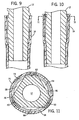
- the shelf 40 serves to separate the locking region or collar 36 of the pipette tip 14 from the sealing area 39 of the pipette 14 in the upper portion of the barrel 38. As best illustrated in Fig. 11 , the collar 36 is distorted out of round when the mounting shaft 12 is fully inserted into the pipette tip 14.
- the shelf 40 serves to isolate the sealing area in the upper portion of the barrel 38 from this distortion, thereby facilitating an effective seal of the sealing ring 54 against the sealing section 32 of the mounting shaft 12. It also serves to accurately locate the tip on the mounting shaft. With multiple channel devices, the tip shelf insures the same vertical mounting distance from tip to tip. This allows precise and consistent tip position during pipetting.
- pipette tips 14 manufactured in accordance with the invention will be typically made of molded plastic, normally polyethylene or polypropylene with or without various additives, as is known in the art.
- This design embodies a locking ring 48 and sealing ring 54 that help the injection molding process. They serve as a way to keep the molded tip on the core of the mold instead of using a puller ring for this process.
- the sealing section 32 of the mounting shaft 12 is tapered in an amount corresponding to the sealing area 39 of the pipette tip in the upper portion of the pipette tip barrel 38.
- the outer surface of the sealing section 32 of the mounting shaft 12 forms an interference fit with the sealing ring 54 on the pipette tip 14 to provide an air-tight seal in order to effectuate accurate aspiration and dispense of liquid into and from the pipette tip barrel 38.
- the locking section 30 of the mounting shaft preferably includes a central cylindrical stabilizing section 56, which is located immediately above and adjacent the stop member 34.
- the central cylindrical stabilizing section 56 on the mounting shaft 12 helps to support the tip 14 in a stable straight orientation.
- One of the advantages of the invention is that the mating locking mechanism allows the tips 14 to be securely mounted in a consistently straight orientation. This allows the use of longer pipette tips 14, which can be particularly desirable in certain applications.
- the diameter of the mounting shaft 12 decreases at the stop member 34 between the central stabilizing section 56 and the upper portion of the sealing section 32 commensurate with the reduction in diameter of the matching pipette tip 14 at its circumferential shelf 40. As mentioned, this reduction is preferably in the range of about .004 to .040 inches.
- the cylindrical stabilizing section 56 and the stop member 34 be continuous around the circumference of the mounting shaft 12 inasmuch as the purpose of these components is to provide secure, stable locking engagement of the pipette tip 14 on the mounting shaft 12 and not to provide a seal.
- the diameter of the mounting shaft 12 may or may not reduce slightly in order to provide clearance between the mounting shaft 12 and the collar 36 of the pipette tip 14.
- the top of the locking section 30 of the mounting shaft 12 preferably includes two or more locking lobes 50 spaced equally around the mounting shaft 12, as well as corresponding recessed areas 58 spanning between the locking lobes 50.
- the lobes 50 include relatively gently sloping inclined ramps 60.
- the preferred slope of the ramp 60 incline with respect to the vertical axis of the mounting shaft 12 is between 10° and 20°.
- the lobes 50 extend outward along the ramp 60 towards the top of the locking section 30 until the lobes 50 turn abruptly inward to form catch surfaces 62.
- the intersection between the ramp surface 60 and the catch surface 62 at the peak of each lobe 50 is preferably slightly rounded.
- the lobes 50 preferably extend outward beyond the outer surface of the cylindrical stabilizing section 56, although the exact preferred dimensions will depend on the amount of taper of the collar 36 in the corresponding matching pipette tip 14 as well as the tip wall thickness.
- the mounting shaft 12 is preferably made from machined steel or machined or molded from chemically resistant plastic such as PEEK or polypropylene, and the specific dimensions are selected to correspond to the dimensions of the matching pipette tip 14.
- the distance between the stop member 34 and the catch surfaces 62 of the lobes 50 of the mounting shaft 12 is selected to correspond to the distance between the circumferential shelf 40 and the locking ring 48 on the collar 36 of the pipette tip 14.
- the first point of contact is when the leading edge of the sealing section 32 on the mounting shaft 12 enters through the circumferential shelf 40 on the pipette tip 14 and contacts the sealing ring 54.
- the sealing ring 54 interference force against the sealing section 32 of the mounting shaft 12 increases.
- the ramp area 60 of the lobes 50 begins to engage the upper portion of the tip collar 36..
- the initial engagement of the sealing ring 54 can be staggered with respect to the engagement of the upper portion of the tip collar 36 in order to lessen insertion force.
- the ramps 60 on the lobes 50 push against the locking ring 48 on the collar 36 of the tip 14 and gently flex the collar 36 and distort it out of round.
- the recessed areas 58 on the mounting shaft 12 provide ample clearance for the straightening of the collar 30 that occurs between the lobes 50. The intent is for the lobes 50 to flex the collar 36 out of round rather than stretch the collar 36.
- the stop member 34 on the mounting shaft engages the circumferential shelf 40 on the pipette tip 14, thus preventing further movement of the shaft 12 into the tip 14.
- the locking ring 48 on the inside surface of the tip collar 36 more or less simultaneously snaps over the lobes 50 on the mounting shaft 12.
- Fig. 11 shows a cross-sectional view looking down on the tip collar 36 being locked onto the mounting shaft 12 over the lobes 50.
- the collar 36 is flexed and distorted to an out of round condition.
- phantom line 70 indicates the outside surface of the collar 36 opening in its preferred round state before being mounted on the mounting shaft 12.
- Phantom line 72 indicates the position of the inside surface of the locking ring 48 of the collar 36 in its preferred round state before being mounted over the lobes 50 on the mounting shaft 12. While the mounted collar 36 is flexed and distorted out of round, the circumferential shelf 40 below the collar 36 remains circular due to its structural integrity.
- the required insertion force is relatively small as compared to other designs which require tight interference fits or stretching of the tip collar.
- the user senses that full engagement is near as the mounting shaft 12 is inserted into the tip 14 because of the slightly increasing resistance of the interference with the sealing ring 54 on the tip and the increasing diameter of the ramp lobes 50. Definite feedback of full engagement occurs when the stop member 34 engages the circumferential shelf 40 and the locking ring 48 snaps over the lobes 50.
- the locking engagement is robust and reduces unintentional dismounting of the tip when a side force is applied to the tip, such as during touching-off procedures.
- the system enables low ejection forces, which is particularly advantageous for hand-held pipettes.
- the out of round distortion of the collar 36 storing energy in the mounted collar 36 is useful for throwing off the tips 14 after use.
- Conventional ejection or stripping mechanisms can be used to push on the top of the collar 36 and push the locking ring 48 over the lobes 50 in order to eject the tips 14.
- Fig. 12 shows a stripper tube 24 moving downward (arrow 22a) to push on the top of the collar 36 to eject the tip 14.
- the locking ring 48 clears the peaks of the lobes 50, the energy stored in the distorted collar 36 is released and facilitates efficient ejection of the tip 14 from the mounting shaft 12.
- the sealing area on the pipette tip may be desirable to move from below the shelf to above the shelf, and configure the mounting shaft so that it accommodates sealing above the stop, rather than below.
- a design preferably, in accordance with the invention, includes a mounting shaft with locking lobes as described above.
- the sealing area on the tip still has to be sufficiently isolated from distortion. This normally requires that the sealing area be located adjacent the shelf and relatively far from the upper portion of the collar that becomes distorted by the mounting shaft lobes.
- Fig. 13 Another embodiment of the invention designed to further reduce insertion and injection forces is illustrated in Fig. 13 .
- the pipette tip 14 has the same or similar configuration to that described in the above Figures, for example Figs. 3-5 .
- the same reference numbers are used in Fig. 13 as in the earlier Figures to describe the components of the pipette tip 14.
- the pipette tip 14 shown in Fig. 13 generally consists of a collar 36, a barrel 38, and a circumferential shelf 40 that extends around the inside bore of the tip 14 and connects the lower end of the collar to the upper end 39 of the barrel 38.
- the pipette tip also includes a circumferential ring 54 on the inside surface of the barrel 38, which in the earlier embodiment served as a circumferential sealing ring but in this embodiment does not serve as a sealing ring because of modifications made to the mounting shaft 112.
- the pipette tip 14 also preferably includes a circumferential locking ring 48 along the inside surface of the collar 36 at or slightly below the opening of the collar 36, as described previously.
- the mounting shaft 112 is modified so that the diameter of the lower sealing section 132 is reduced in comparison to the earlier embodiment.
- the configuration of the locking section 130 of the modified mounting shaft 112 is quite similar to that described in the earlier embodiments, especially with respect to the lobes 50 and the step 34 and the interaction of the lobes 50 and the step 34 with the pipette tip 14, with a caveat being that it has been found that the diameter of the central stabilizing section 156 may be reduced slightly to provide less interference between the pipette tip 14 and the mounting shaft 112 when the mounting shaft 112 is inserted into the pipette tip 14.
- the lower sealing section 132 of the mounting shaft 112 in Fig. 13 is modified to reduce the diameter of the lower sealing section at the tip 133 of the mounting shaft 112 so that there is little or no interference between the circumferential ring 54 of the pipette tip 14 and the lower portion 132 of the mounting shaft 112.
- An annular groove 135 containing a sealing ring 137 is located at the upper end of the lower sealing section 132 of the mounting shaft 112.
- the sealing ring 137 is preferably an O-ring made of flouroelastomeric material.
- the preferred O-ring has a 0,762 mm (.030 inches) cross-section, and a 3,3 mm (.130) inside diameter which is stretched to a 3,73 mm (.147) groove diameter, which provides a 0,152 mm (.006 inch) interference fit between the O-ring 137 and the upper portion 39 of the barrel 38 of the pipette tip 14.
- the preferred O-ring has a 0.94 mm (.037 inch) cross-section, and a 4,37 mm (.172) inside diameter, which is stretched over a groove diameter of 4.8 mm (.189 inches) again to produce an interference of about 0.152 mm (.006 inches) between the O-ring 137 and the upper portion 39 of the barrel 38 of the pipette tip 14.
- the upper edge of the groove 139 is no more than about 0.381 mm (0.015inches), e.g. about 0.203 mm (.008 inches), below the top 41 of the inside surface of the barrel 38 of the pipette tip 14.
- the sealing O-ring 137 does not travel a substantial distance after it is in contact with the pipette tip 14 barrel 38.
- the lower section 132 of the mounting shaft 112 includes a tapered section 141 located proximate the groove 139 above the location where the circumferential ring 54 on the pipette tip 14 would be located after the mounting shaft 112 is fully inserted into the tip 14.
- the tapered portion 141 tapers outward as it approaches the groove 139 in order to protect the O-ring seal 137 from damage that might otherwise be caused by contact with the pipette tip shelf 40 as the mounting shaft 112 is inserted into the pipette tip 14.
- FIGs. 14-16 Another embodiment of the invention designed to further reduce the insertion and ejection forces is disclosed in Figs. 14-16 .
- the embodiment of the invention illustrated in Figs. 14-16 is particularly useful when it is not desirable or practical to use an O-ring seal, yet it is desirable to further reduce insertion and ejection forces, such as in hand-held multi-channel pipettor applications.
- the configuration of the pipette tip mounting shaft 212 is modified, yet as with the embodiment disclosed in Fig. 13 , it is preferred that the configuration of the pipette tip 14 remain similar to the earlier embodiments. For example, it has been found that the embodiment shown in Figs.
- the lower section 232 of the mounting shaft 212 is modified to reduce the diameter of the lowermost portion 233.
- the diameter of the lowermost portion 233 of the mounting shaft is reduced so that there is little or no interference between the circumferential sealing ring 54 on the pipette tip 14 and the lowermost portion 233 of the mounting shaft.
- the lower section 232 of the mounting shaft 212 contains a frustoconical sealing area 200 located in the vicinity that the circumferential sealing ring 54 is expected to reside when the mounting shaft 212 is fully inserted into the tip 14.
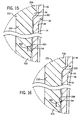
- Figs. 15 and 16 are schematic views illustrating the operation of the frustoconical sealing area 200 on the mounting shaft 212. It should be understood that the dimensions of the frustoconical sealing area 200 are exaggerated in Figs. 15 and 16 in order to illustrate the concept of this aspect of the invention. Referring in particular to Figs. 15 and 16 , sealing of the pipette tip 14 to the mounting shaft 212 is due to the interference between the circumferential sealing ring 54 on the pipette tip 14 and the frustoconical sealing area 200 on the mounting shaft 212. The specific dimensions of the frustoconical sealing area 200 are determined to account for normal manufacturing tolerances for molded pipette tips.
- molded pipette tips having relatively small dimensions within normal manufacturing tolerances will form an interference fit at the lower portion of the frustoconical section 200 as the mounting shaft 212 is inserted into the pipette tip, as shown in Fig. 15 .
- molded pipette tips having a relatively large dimension within normal manufacturing tolerances, will engage towards the upper portion of the frustoconical sealing area 200 as shown in Fig. 16 .
- Below the frustoconical sealing area 200 it is desirable that the mounting shaft 212 does not interfere with the sealing ring 54 as the mounting shaft is inserted into the pipette tip 14. Note that in Fig.
- the preferred range of vertical travel 203 for the frustoconical sealing area 200 be .025 inches for 12.5 ⁇ liter pipette tips and that the frustoconical area have an included angle of 5°; whereas, for 125 ⁇ liter pipette tips, the preferred range of vertical travel is 0.762 mm (.03 inches)with an included taper angle of 4°. These dimensions were selected to provide a nominal interference of 0.0508 mm (.002 inches) to ensure an effective seal, and were selected so that the range would include the mean pipette tip dimension at the sealing ring 54 plus or minus three times the standard deviation.
Landscapes
- Health & Medical Sciences (AREA)
- Clinical Laboratory Science (AREA)
- Chemical & Material Sciences (AREA)
- Chemical Kinetics & Catalysis (AREA)
- Automatic Analysis And Handling Materials Therefor (AREA)
- Devices For Use In Laboratory Experiments (AREA)
- Sampling And Sample Adjustment (AREA)
Claims (12)
- Système de pipetage comprenant :un embout de pipette (14) jetable ayant :un corps cylindrique (38) avec une ouverture inférieure (44) à travers laquelle le liquide est aspiré dans le corps cylindrique et distribué à partir du corps cylindrique, le corps cylindrique ayant une zone d'étanchéité au niveau d'une extrémité supérieure du corps cylindrique,un collier (36) ayant une ouverture supérieure (42) pour recevoir une tige de montage (12) de pipette, l'extrémité inférieure du collier ayant un plus grand diamètre intérieur que le diamètre intérieur au niveau de l'extrémité supérieure du corps cylindrique, etun rebord circonférentiel (40) qui raccorde l'extrémité inférieure du collier à l'extrémité supérieure du corps cylindrique ; etune tige de montage (12) de pipette comprenant :dans lequel la section inférieure comprend une rainure annulaire (135) avec une bague d'étanchéité (137) positionnée dans la rainure annulaire, etune section inférieure, etune section de verrouillage supérieure (130), la section de verrouillage de la tige de montage comprenant une butée (34) qui vient en prise avec le rebord circonférentiel (40) de l'embout de pipette (14) lorsque la tige de montage (12) est complètement insérée dans le collier (36) de l'embout de pipette (14), deux lobes (50) ou plus s'étendant vers l'extérieur espacés à égale distance autour de la section de verrouillage (130) de la tige de montage (12) et positionnés au-dessus de la butée (34) sur la tige de montage pour venir en prise avec une surface intérieure du collier, et des parties évidées en relief (58) dans la section de verrouillage supérieure de la tige de montage et s'étendant entre les lobes (50), de sorte que le collier se déforme vers l'extérieur au niveau des lobes et vers l'intérieur au niveau des parties en relief lorsque l'embout de pipette est complètement monté sur la tige de montage ;
dans lequel la bague d'étanchéité (137) vient en prise avec la zone d'étanchéité au niveau de l'extrémité supérieure du corps cylindrique de l'embout de pipette jetable lorsque la tige de montage est complètement insérée dans l'embout de pipette. - Système de pipetage selon la revendication 1, dans lequel :la surface intérieure du corps cylindrique d'embout de pipette comprend une bague de stabilisation circonférentielle (54) s'étendant vers l'intérieur à partir de la surface intérieure du corps cylindrique au-dessous du rebord circonférentiel ; etla bague d'étanchéité (137) sur la section inférieure sur la tige de montage est positionnée au-dessous de la section de verrouillage (130) sur la tige de montage et vient en prise avec la surface intérieure du corps cylindrique d'embout à un emplacement situé au-dessus de la bague de stabilisation circonférentielle (54) lorsque la tige de montage est complètement insérée dans l'embout de pipette.
- Système de pipetage selon la revendication 1, dans lequel la bague d'étanchéité (137) est un joint torique fait d'un matériau élastomère.
- Système de pipetage selon la revendication 1, dans lequel la bague d'étanchéité (137) est un joint torique et le bord supérieur de la rainure dans laquelle est positionné le joint torique ne se trouve pas à plus d'environ 0,381 mm au-dessous du rebord circonférentiel sur l'embout de pipette lorsque la tige de montage est complètement insérée dans l'embout de pipette.
- Système de pipetage selon la revendication 4, dans lequel la ligne centrale du joint torique (137) ne se trouve pas à plus d'environ 0,762 mm au-dessous du rebord circonférentiel (40) le long de la surface intérieure du corps cylindrique de l'embout de pipette (14) lorsque la tige de montage (12) est complètement insérée dans l'embout de pipette (14).
- Système de pipetage selon la revendication 2, dans lequel le diamètre de la section inférieure sur la tige de montage (12) au-dessous de la rainure (135) pour la bague d'étanchéité (137) devient plus petit, évitant ainsi un ajustement avec serrage entre la tige de montage (12) et la bague de stabilisation (54) sur l'embout de pipette (14).
- Système de pipetage comprenant :un embout de pipette jetable ayant :un corps cylindrique (38) avec une ouverture inférieure à travers laquelle le liquide est aspiré dans le corps cylindrique et distribué à partir du corps cylindrique, une bague d'étanchéité circonférentielle (56) le long d'une surface intérieure du corps cylindrique,un collier (36) ayant une ouverture supérieure qui reçoit une extrémité inférieure d'une tige de montage (12) de pipette, une extrémité inférieure du collier ayant un plus grand diamètre intérieur que le diamètre intérieur de l'extrémité supérieure du corps cylindrique, etun rebord circonférentiel (40) qui raccord l'extrémité inférieure du collier à l'extrémité supérieure du corps cylindrique ; etune tige de montage (12) de pipette comprenant :dans lequel la section d'étanchéité inférieure (232) a une forme tronconique et est positionnée au-dessous de la section de verrouillage (230), dans lequel la section d'étanchéité tronconique sur la tige de montage a un angle inclus compris entre environ 4° et environ 7° et fournit un ajustement serré avec la bague d'étanchéité circonférentielle (56) sur l'embout de pipette lorsque la tige de montage est insérée dans l'embout de pipette, la hauteur de la section tronconique étant adaptée à une plage sélectionnée de déplacement vertical avant la mise en prise complète de la butée sur la tige de montage contre le rebord de l'embout de pipette.une section de verrouillage supérieure (230), la section de verrouillage de la tige de montage comprenant une butée (34) qui vient en prise avec le rebord circonférentiel (40) de l'embout de pipette lorsque la tige de montage est complètement insérée dans le collier de l'embout, deux lobes (50) ou plus s'étendant vers l'extérieur, espacés à égale distance autour de la section de verrouillage de la tige de montage et positionnés au-dessus de la butée sur la tige de montage pour venir en prise avec la surface intérieure du collier, et des parties de relief évidées (58) dans la section de verrouillage supérieure de la tige de montage et s'étendant entre les lobes, de sorte que le collier se déforme vers l'extérieur au niveau des lobes et vers l'intérieur au niveau des parties en relief lorsque l'embout de pipette est complètement monté sur la tige de montage ; etune section d'étanchéité inférieure (232) ;
- Système de pipetage selon la revendication 7, dans lequel le diamètre intérieur de la bague d'étanchéité circonférentielle (56) sur l'embout de pipette est au moins égal ou légèrement supérieur au diamètre de la tige de montage au-dessous de la section d'étanchéité tronconique.
- Système de pipetage selon la revendication 1 ou 7, dans lequel le système est un système de pipetage manuel à déplacement d'air.
- Système de pipetage selon la revendication 1 ou 7, dans lequel chaque lobe (50) comprend une partie de rampe inclinée (60) qui facilite la déformation du collier (36) d'embout de pipette lorsque la tige de montage (12) est insérée dans l'embout de pipette (14).
- Système de pipetage selon la revendication 1 ou 7, dans lequel la tige de montage (12) a au moins trois lobes (50) pour venir en prise avec une surface intérieure du collier.
- Système de pipetage selon la revendication 1 ou 7, dans lequel l'embout de pipette jetable comprend en outre un élément de verrouillage (48) sensiblement circonférentiel s'étendant vers l'intérieur à partir de la surface intérieure du collier (36), dans lequel lorsque la tige de montage (12) est complètement insérée dans le collier (36) de l'embout de pipette (14), l'élément de verrouillage (48) sur l'embout de pipette vient en prise avec les lobes (50) sur la tige de montage, ce qui se traduit par une mise en prise de verrouillage à arc-boutement lorsque la bague de verrouillage franchit les lobes sur la tige de montage jusqu'à une mise en prise de verrouillage.
Applications Claiming Priority (2)
| Application Number | Priority Date | Filing Date | Title |
|---|---|---|---|
| US11/934,381 US7662344B2 (en) | 2006-10-24 | 2007-11-02 | Locking pipette tip and mounting shaft |
| PCT/US2008/081716 WO2009058952A1 (fr) | 2007-11-02 | 2008-10-30 | Embout de pipette de blocage et arbre de montage |
Publications (2)
| Publication Number | Publication Date |
|---|---|
| EP2214832A1 EP2214832A1 (fr) | 2010-08-11 |
| EP2214832B1 true EP2214832B1 (fr) | 2015-04-08 |
Family
ID=40325807
Family Applications (1)
| Application Number | Title | Priority Date | Filing Date |
|---|---|---|---|
| EP20080844062 Active EP2214832B1 (fr) | 2007-11-02 | 2008-10-30 | Embout de pipette et tige de montage |
Country Status (4)
| Country | Link |
|---|---|
| US (4) | US7662344B2 (fr) |
| EP (1) | EP2214832B1 (fr) |
| JP (1) | JP5662152B2 (fr) |
| WO (1) | WO2009058952A1 (fr) |
Families Citing this family (50)
| Publication number | Priority date | Publication date | Assignee | Title |
|---|---|---|---|---|
| US7662344B2 (en) * | 2006-10-24 | 2010-02-16 | Viaflo Corporation | Locking pipette tip and mounting shaft |
| CA3138078C (fr) | 2007-10-02 | 2024-02-13 | Labrador Diagnostics Llc | Dispositifs modulaires a utiliser sur place et leurs utilisations |
| US8277757B2 (en) * | 2009-09-29 | 2012-10-02 | Integra Biosciences Corp. | Pipette tip mounting shaft |
| JP5400251B2 (ja) | 2010-05-03 | 2014-01-29 | インテグラ バイオサイエンシズ コープ. | 手動で配向されるマルチチャネル用電子式ピペットチップの位置決め |
| US8367022B2 (en) | 2010-05-03 | 2013-02-05 | Integra Biosciences Corp. | Unintended motion control for manually directed multi-channel electronic pipettor |
| EP2566618B8 (fr) | 2010-05-03 | 2014-07-09 | Integra Biosciences AG | Régulateur de mouvement involontaire pour pipeteur multi-canaux électronique aux controle manuelle |
| FI123648B (fi) * | 2010-11-15 | 2013-08-30 | Thermo Fisher Scientific Oy | Monikanavapipetti |
| MX349288B (es) | 2011-01-21 | 2017-07-21 | Theranos Inc | Sistemas y metodos para maximizacion de uso de muestras. |
| JP2014508034A (ja) | 2011-01-28 | 2014-04-03 | インテグラ バイオサイエンシズ コープ. | マルチチャンネルウェルプレート充填システム |
| US8524170B2 (en) * | 2011-02-22 | 2013-09-03 | Rainin Instrument, Llc | Pipette and sealing tip |
| US9664702B2 (en) | 2011-09-25 | 2017-05-30 | Theranos, Inc. | Fluid handling apparatus and configurations |
| US20140170735A1 (en) | 2011-09-25 | 2014-06-19 | Elizabeth A. Holmes | Systems and methods for multi-analysis |
| US9619627B2 (en) | 2011-09-25 | 2017-04-11 | Theranos, Inc. | Systems and methods for collecting and transmitting assay results |
| US8435738B2 (en) | 2011-09-25 | 2013-05-07 | Theranos, Inc. | Systems and methods for multi-analysis |
| US8840838B2 (en) | 2011-09-25 | 2014-09-23 | Theranos, Inc. | Centrifuge configurations |
| US8475739B2 (en) | 2011-09-25 | 2013-07-02 | Theranos, Inc. | Systems and methods for fluid handling |
| US9632102B2 (en) | 2011-09-25 | 2017-04-25 | Theranos, Inc. | Systems and methods for multi-purpose analysis |
| US9268915B2 (en) | 2011-09-25 | 2016-02-23 | Theranos, Inc. | Systems and methods for diagnosis or treatment |
| US9810704B2 (en) | 2013-02-18 | 2017-11-07 | Theranos, Inc. | Systems and methods for multi-analysis |
| US9250229B2 (en) | 2011-09-25 | 2016-02-02 | Theranos, Inc. | Systems and methods for multi-analysis |
| US10012664B2 (en) | 2011-09-25 | 2018-07-03 | Theranos Ip Company, Llc | Systems and methods for fluid and component handling |
| FI125139B (en) * | 2012-08-20 | 2015-06-15 | Thermo Fisher Scientific Oy | Pipette and method for attaching the pipette tip to the pipette |
| MX2012010987A (es) * | 2012-09-24 | 2014-03-24 | Diana Elizabeth Calva Mendez | Pipeta con boquilla movil. |
| US10343156B2 (en) * | 2013-03-15 | 2019-07-09 | Nalge Nunc International Corporation | Tapered pipette |
| USD703344S1 (en) | 2013-06-18 | 2014-04-22 | Corning Incorporated | Pipette tip |
| US10345145B2 (en) | 2014-01-23 | 2019-07-09 | Specturm Perception Llc | Miniaturized spectrometer for sensitive and robust laboratory and field use |
| US10710067B2 (en) | 2014-01-23 | 2020-07-14 | Spectrum Perception Llc | Pipette tip with integrated light guides in the body and method of spectroscopic analysis using same |
| CH709307A1 (de) | 2014-02-26 | 2015-08-28 | Tecan Trading Ag | Transportwerkzeug zum Transportieren eines Laborartikels. |
| US9987427B1 (en) | 2014-06-24 | 2018-06-05 | National Technology & Engineering Solutions Of Sandia, Llc | Diagnostic/drug delivery “sense-respond” devices, systems, and uses thereof |
| EP3160648B1 (fr) | 2014-06-30 | 2024-04-03 | Ventana Medical Systems, Inc. | Systèmes de traitement d'échantillon, ensembles pipette et procédés pour préparer des réactifs |
| US9580288B2 (en) * | 2014-09-05 | 2017-02-28 | Dianna Ploss | Water dispenser cover |
| USD746632S1 (en) | 2014-10-01 | 2016-01-05 | Dianna Ploss | Water dispenser cover |
| US9860392B2 (en) | 2015-06-05 | 2018-01-02 | Silicon Laboratories Inc. | Direct-current to alternating-current power conversion |
| US20170189899A1 (en) * | 2015-12-30 | 2017-07-06 | Priyanshu Gupta | Multi-piece fluid transfer tip |
| CH712010B1 (de) * | 2016-01-11 | 2021-10-15 | Integra Biosciences Ag | Pipette mit Abwurfmechanismus für Pipettenspitzen. |
| US11235318B2 (en) | 2016-06-15 | 2022-02-01 | Hamilton Company | Pipetting device, pipette tip coupler, and pipette tip: devices and methods |
| US10898892B2 (en) | 2016-06-15 | 2021-01-26 | Hamilton Company | Pipetting device, pipette tip coupler, and pipette tip: devices and methods |
| US11065614B2 (en) | 2016-06-15 | 2021-07-20 | Hamilton Company | Pipetting device, pipette tip coupler, and pipette tip: devices and methods |
| CN110385153B (zh) | 2016-06-15 | 2022-05-17 | 汉密尔顿公司 | 移液装置、移液管末梢联接器和移液管末梢:装置和方法 |
| FR3052688B1 (fr) * | 2016-06-17 | 2018-07-06 | Gilson Sas | Embout de systeme de pipetage presentant une conicite double |
| WO2018061072A1 (fr) * | 2016-09-27 | 2018-04-05 | 株式会社 エー・アンド・デイ | Adaptateur de montage de pointe de pipette |
| US11167282B2 (en) | 2017-01-31 | 2021-11-09 | HighRes Biosolutions, Inc. | Auto-pipetting apparatus and method |
| CH714486A1 (de) | 2017-12-21 | 2019-06-28 | Integra Biosciences Ag | Probenverteilsystem und Verfahren zum Verteilen von Proben. |
| NL2024277B1 (en) * | 2019-11-21 | 2021-08-11 | Imcomet B V | Interstitial fluid removal device |
| WO2021146126A1 (fr) * | 2020-01-15 | 2021-07-22 | Perkinelmer Health Sciences, Inc. | Pointes de pipette et procédés et systèmes les comprenant |
| EP4063013B1 (fr) * | 2021-03-26 | 2024-12-04 | Eppendorf SE | Pointe de pipette |
| JP2023167656A (ja) * | 2022-05-12 | 2023-11-24 | ヤマハ発動機株式会社 | 吸引チップおよび生体対象物移動装置 |
| US20240307884A1 (en) | 2023-03-17 | 2024-09-19 | Integra Biosciences Ag | Pipette tips and rack system for liquid handling equipment |
| CN120835815A (zh) | 2023-03-17 | 2025-10-24 | 因特格拉生物科学股份公司 | 用于液体处理设备的移液管吸头和支架系统 |
| EP4717356A1 (fr) | 2024-09-26 | 2026-04-01 | Trasis S.A. | Embout de pipette pour transfert ventilé |
Family Cites Families (55)
| Publication number | Priority date | Publication date | Assignee | Title |
|---|---|---|---|---|
| DE7518809U (de) * | 1975-06-12 | 1978-09-14 | Eppendorf Geraetebau Netheler & Hinz Gmbh, 2000 Hamburg | Pipettenspitze |
| US4917274A (en) * | 1983-09-27 | 1990-04-17 | Maurice Asa | Miniscule droplet dispenser tip |
| FI843976L (fi) | 1983-10-13 | 1985-04-14 | Cetus Corp | Utbytbar pipettspets. |
| US4824641A (en) * | 1986-06-20 | 1989-04-25 | Cetus Corporation | Carousel and tip |
| US5032343A (en) * | 1986-08-11 | 1991-07-16 | Multi-Technology, Inc | Method for producing medical micro pipette tips for difficult to reach places |
| US4721680A (en) * | 1986-08-11 | 1988-01-26 | Multi-Technology, Inc. | Methods of using micro pipette tips |
| DE3635598A1 (de) * | 1986-10-20 | 1988-05-05 | Eppendorf Geraetebau Netheler | Pipettiervorrichtung mit einem aufsteckkonus fuer eine pipettenspitze sowie pipettenspitze fuer eine solche pipettiervorrichtung |
| US4748859A (en) * | 1987-03-06 | 1988-06-07 | Rainin Instrument Co., Inc. | Disposable pipette tip |
| US5306510A (en) * | 1988-01-14 | 1994-04-26 | Cyberlab, Inc. | Automated pipetting system |
| DE3824767A1 (de) * | 1988-07-21 | 1990-02-01 | Eppendorf Geraetebau Netheler | Aufsteckbare pipettenspitze in form eines entsprechend einem aufsteckkopfstueck, insbesondere konus einer pipette, wenigstens abschnittsweise ausgefuehrten gefaesses |
| US5200151A (en) * | 1990-05-21 | 1993-04-06 | P B Diagnostic Systems, Inc. | Fluid dispensing system having a pipette assembly with preset tip locator |
| FI86812C (fi) | 1991-01-07 | 1992-10-26 | Labsystems Oy | Foertraengningspipett |
| US5525302A (en) * | 1991-02-01 | 1996-06-11 | Astle; Thomas W. | Method and device for simultaneously transferring plural samples |
| US5232669A (en) * | 1991-11-08 | 1993-08-03 | Abbott Laboratories | Pipette tip with self-aligning and self-sealing features |
| CA2147560A1 (fr) * | 1994-04-22 | 1995-10-23 | Donald H. Devaughn | Appareil avec haut de pipette resistant au transfert de liquide et d'aerosol; methode de reduction de transfert |
| JP3387649B2 (ja) | 1994-09-16 | 2003-03-17 | 富士写真フイルム株式会社 | 点着チップ |
| US5948359A (en) * | 1997-03-21 | 1999-09-07 | Biogenex Laboratories | Automated staining apparatus |
| US6499363B1 (en) * | 1997-12-12 | 2002-12-31 | The Sailor Pen Co., Ltd. | Tip for pipette and pipette with the same |
| US6495106B1 (en) * | 1998-03-24 | 2002-12-17 | Biogenex Laboratories | Automated staining apparatus |
| US6168761B1 (en) | 1998-11-06 | 2001-01-02 | Rainin Instrument Co., Inc. | Pipette with improved pipette tip and mounting shaft |
| US6197259B1 (en) | 1998-11-06 | 2001-03-06 | Rainin Instrument Co., Inc. | Easy eject pipette tip |
| US6248295B1 (en) * | 1998-11-06 | 2001-06-19 | Rainin Instrument Co., Inc. | Pipette with improved pipette tip and mounting shaft combination |
| DE19917375C2 (de) * | 1999-04-16 | 2001-09-27 | Hamilton Bonaduz Ag Bonaduz | Pipettiereinheit |
| JP2001033463A (ja) * | 1999-07-23 | 2001-02-09 | Cosmo Tec:Kk | 液体分注装置 |
| US6399024B1 (en) * | 2000-02-01 | 2002-06-04 | Incyte Genomics, Inc. | Multichannel pipette head |
| DE10013511A1 (de) * | 2000-03-20 | 2001-10-11 | Brand Gmbh & Co Kg | Mehrkanal-Pipettiereinrichtung sowie Pipettenschaft dafür |
| US6749812B2 (en) * | 2000-06-26 | 2004-06-15 | Vistalab Technologies | Automatic pipette detipping |
| JP4271835B2 (ja) | 2000-08-18 | 2009-06-03 | アークレイ株式会社 | ピペット装置 |
| US6596240B2 (en) * | 2001-01-12 | 2003-07-22 | Porex Corporation | Pipette tip for easy mounting and ejecting from a pipette |
| US6973845B2 (en) * | 2001-01-18 | 2005-12-13 | Beckman Coulter, Inc. | Low insertion force tip/mandrel |
| US6568288B2 (en) * | 2001-06-29 | 2003-05-27 | Rainin Instrument, Llc | Pipette with improved pipette tip and mounting shaft |
| JP2003038966A (ja) * | 2001-07-31 | 2003-02-12 | Arkray Inc | 分注チップおよびそれを装着した分注装置 |
| US7335337B1 (en) * | 2001-09-11 | 2008-02-26 | Smith James C | Ergonomic pipette tip and adapters |
| US6967004B2 (en) * | 2001-10-30 | 2005-11-22 | Rainin Instrument, Llc | Pipette with improved pipette tip and mounting shaft |
| JP3648487B2 (ja) * | 2002-03-01 | 2005-05-18 | アロカ株式会社 | 分注装置用ノズルチップ |
| US6780381B2 (en) * | 2002-04-08 | 2004-08-24 | Felix H. Yiu | Pipettor and externally sealed pipette tip |
| DE10222511B4 (de) * | 2002-05-22 | 2005-03-17 | Eppendorf Ag | Pipettenspitze |
| DE10229788B4 (de) | 2002-07-03 | 2004-08-05 | Eppendorf Ag | Pipettenspitze |
| US20040071602A1 (en) * | 2002-10-15 | 2004-04-15 | Yiu Felix H. | Pipettor head adapter |
| DE10345324B3 (de) * | 2003-09-30 | 2004-08-19 | Eppendorf Ag | Pipettenspitze |
| US7641859B2 (en) * | 2004-02-11 | 2010-01-05 | Matrix Technologies Corporation | Pipette tip mounting and ejection assembly and associated pipette tip |
| US20050255005A1 (en) * | 2004-05-13 | 2005-11-17 | Arta Motadel | Stackable pipette tips having increased accuracy |
| US20050265900A1 (en) * | 2004-05-27 | 2005-12-01 | Gard Douglas J | Pipetting system with selective pipette tip loading |
| US20060171851A1 (en) * | 2005-01-28 | 2006-08-03 | Arta Motadel | Liquid sampling utilizing ribbed pipette tip for barrier penetration |
| DE102005005437A1 (de) * | 2005-02-05 | 2006-08-10 | Eppendorf Ag | Filterpipettenspitze |
| FR2882273B1 (fr) * | 2005-02-18 | 2007-06-01 | Gilson Sas Soc Par Actions Sim | Embout pour pipette de prelevement, et pipette ainsi equipee |
| EP1881870A1 (fr) | 2005-05-17 | 2008-01-30 | LIEPOLD, Gerhard | Aiguille |
| EP1862219B1 (fr) * | 2006-05-29 | 2018-02-07 | Qiagen GmbH | Appareil pour retenir un embout à pipette et pipette utilisant ledit embout |
| DE102006036764B4 (de) | 2006-08-05 | 2012-11-29 | Eppendorf Ag | Pipettiersystem |
| US7662343B2 (en) * | 2006-10-24 | 2010-02-16 | Viaflo Corporation | Locking pipette tip and mounting shaft |
| US7662344B2 (en) * | 2006-10-24 | 2010-02-16 | Viaflo Corporation | Locking pipette tip and mounting shaft |
| US8202495B1 (en) * | 2008-06-23 | 2012-06-19 | Smith James C | Ergonomic pipette tip |
| US8277757B2 (en) * | 2009-09-29 | 2012-10-02 | Integra Biosciences Corp. | Pipette tip mounting shaft |
| DE102009049783A1 (de) * | 2009-10-19 | 2011-04-21 | Eppendorf Ag | Elektrisch leitfähige Pipettenspitze |
| CN203941178U (zh) * | 2011-05-20 | 2014-11-12 | 珀金埃尔默保健科学公司 | 实验室部件和液体装卸系统及辅助性可流动材料装卸系统 |
-
2007
- 2007-11-02 US US11/934,381 patent/US7662344B2/en active Active
-
2008
- 2008-10-30 WO PCT/US2008/081716 patent/WO2009058952A1/fr not_active Ceased
- 2008-10-30 EP EP20080844062 patent/EP2214832B1/fr active Active
- 2008-10-30 JP JP2010532231A patent/JP5662152B2/ja active Active
-
2009
- 2009-10-14 US US12/578,714 patent/US8501118B2/en active Active
-
2013
- 2013-07-29 US US13/952,731 patent/US8877513B2/en active Active
-
2014
- 2014-10-27 US US14/524,685 patent/US9333500B2/en active Active
Also Published As
| Publication number | Publication date |
|---|---|
| JP2011502752A (ja) | 2011-01-27 |
| JP5662152B2 (ja) | 2015-01-28 |
| EP2214832A1 (fr) | 2010-08-11 |
| US20150086447A1 (en) | 2015-03-26 |
| WO2009058952A1 (fr) | 2009-05-07 |
| US20080286157A1 (en) | 2008-11-20 |
| US20100034706A1 (en) | 2010-02-11 |
| US8877513B2 (en) | 2014-11-04 |
| US20130306155A1 (en) | 2013-11-21 |
| US9333500B2 (en) | 2016-05-10 |
| US7662344B2 (en) | 2010-02-16 |
| US8501118B2 (en) | 2013-08-06 |
Similar Documents
| Publication | Publication Date | Title |
|---|---|---|
| EP2214832B1 (fr) | Embout de pipette et tige de montage | |
| EP2086683B1 (fr) | Embout de pipette et tige de montage | |
| US8277757B2 (en) | Pipette tip mounting shaft | |
| JP2011502752A5 (ja) | ロックピペットチップ及び取り付けシャフト | |
| WO2009039039A1 (fr) | Mécanisme d'éjection d'embout de pipette | |
| EP2311566A1 (fr) | Ensemble de montage et d'éjection de pointe de pipette et pointe de pipette associée | |
| US20120213677A1 (en) | Pipette and sealing tip | |
| US9901919B2 (en) | Pipette with piston rotation lock | |
| US6953449B2 (en) | Hypodermic syringe having plunger pull-out stopping structure | |
| US20240307865A1 (en) | Pipette tip and mounting shaft | |
| US20260108873A1 (en) | Pipette tip and mounting shaft with offset locking feature | |
| CN115121307B (zh) | 移液头 | |
| WO2024194741A1 (fr) | Pointes de pipette et système de rayonnage pour équipement de manipulation de liquide |
Legal Events
| Date | Code | Title | Description |
|---|---|---|---|
| PUAI | Public reference made under article 153(3) epc to a published international application that has entered the european phase |
Free format text: ORIGINAL CODE: 0009012 |
|
| 17P | Request for examination filed |
Effective date: 20100528 |
|
| AK | Designated contracting states |
Kind code of ref document: A1 Designated state(s): AT BE BG CH CY CZ DE DK EE ES FI FR GB GR HR HU IE IS IT LI LT LU LV MC MT NL NO PL PT RO SE SI SK TR |
|
| AX | Request for extension of the european patent |
Extension state: AL BA MK RS |
|
| DAX | Request for extension of the european patent (deleted) | ||
| RAP1 | Party data changed (applicant data changed or rights of an application transferred) |
Owner name: INTEGRA BIOSCIENCES CORP. |
|
| 17Q | First examination report despatched |
Effective date: 20130806 |
|
| RAP1 | Party data changed (applicant data changed or rights of an application transferred) |
Owner name: INTEGRA BIOSCIENCES AG |
|
| GRAP | Despatch of communication of intention to grant a patent |
Free format text: ORIGINAL CODE: EPIDOSNIGR1 |
|
| INTG | Intention to grant announced |
Effective date: 20140919 |
|
| GRAP | Despatch of communication of intention to grant a patent |
Free format text: ORIGINAL CODE: EPIDOSNIGR1 |
|
| GRAS | Grant fee paid |
Free format text: ORIGINAL CODE: EPIDOSNIGR3 |
|
| GRAA | (expected) grant |
Free format text: ORIGINAL CODE: 0009210 |
|
| INTG | Intention to grant announced |
Effective date: 20150217 |
|
| AK | Designated contracting states |
Kind code of ref document: B1 Designated state(s): AT BE BG CH CY CZ DE DK EE ES FI FR GB GR HR HU IE IS IT LI LT LU LV MC MT NL NO PL PT RO SE SI SK TR |
|
| REG | Reference to a national code |
Ref country code: GB Ref legal event code: FG4D |
|
| REG | Reference to a national code |
Ref country code: CH Ref legal event code: NV Representative=s name: MICHELI AND CIE SA, CH Ref country code: CH Ref legal event code: EP |
|
| REG | Reference to a national code |
Ref country code: IE Ref legal event code: FG4D |
|
| REG | Reference to a national code |
Ref country code: AT Ref legal event code: REF Ref document number: 720106 Country of ref document: AT Kind code of ref document: T Effective date: 20150515 |
|
| REG | Reference to a national code |
Ref country code: DE Ref legal event code: R096 Ref document number: 602008037617 Country of ref document: DE Effective date: 20150521 |
|
| REG | Reference to a national code |
Ref country code: AT Ref legal event code: MK05 Ref document number: 720106 Country of ref document: AT Kind code of ref document: T Effective date: 20150408 |
|
| REG | Reference to a national code |
Ref country code: NL Ref legal event code: VDEP Effective date: 20150408 |
|
| REG | Reference to a national code |
Ref country code: LT Ref legal event code: MG4D |
|
| PG25 | Lapsed in a contracting state [announced via postgrant information from national office to epo] |
Ref country code: NL Free format text: LAPSE BECAUSE OF FAILURE TO SUBMIT A TRANSLATION OF THE DESCRIPTION OR TO PAY THE FEE WITHIN THE PRESCRIBED TIME-LIMIT Effective date: 20150408 |
|
| PG25 | Lapsed in a contracting state [announced via postgrant information from national office to epo] |
Ref country code: LT Free format text: LAPSE BECAUSE OF FAILURE TO SUBMIT A TRANSLATION OF THE DESCRIPTION OR TO PAY THE FEE WITHIN THE PRESCRIBED TIME-LIMIT Effective date: 20150408 Ref country code: FI Free format text: LAPSE BECAUSE OF FAILURE TO SUBMIT A TRANSLATION OF THE DESCRIPTION OR TO PAY THE FEE WITHIN THE PRESCRIBED TIME-LIMIT Effective date: 20150408 Ref country code: NO Free format text: LAPSE BECAUSE OF FAILURE TO SUBMIT A TRANSLATION OF THE DESCRIPTION OR TO PAY THE FEE WITHIN THE PRESCRIBED TIME-LIMIT Effective date: 20150708 Ref country code: HR Free format text: LAPSE BECAUSE OF FAILURE TO SUBMIT A TRANSLATION OF THE DESCRIPTION OR TO PAY THE FEE WITHIN THE PRESCRIBED TIME-LIMIT Effective date: 20150408 Ref country code: ES Free format text: LAPSE BECAUSE OF FAILURE TO SUBMIT A TRANSLATION OF THE DESCRIPTION OR TO PAY THE FEE WITHIN THE PRESCRIBED TIME-LIMIT Effective date: 20150408 Ref country code: PT Free format text: LAPSE BECAUSE OF FAILURE TO SUBMIT A TRANSLATION OF THE DESCRIPTION OR TO PAY THE FEE WITHIN THE PRESCRIBED TIME-LIMIT Effective date: 20150810 |
|
| PG25 | Lapsed in a contracting state [announced via postgrant information from national office to epo] |
Ref country code: IS Free format text: LAPSE BECAUSE OF FAILURE TO SUBMIT A TRANSLATION OF THE DESCRIPTION OR TO PAY THE FEE WITHIN THE PRESCRIBED TIME-LIMIT Effective date: 20150808 Ref country code: LV Free format text: LAPSE BECAUSE OF FAILURE TO SUBMIT A TRANSLATION OF THE DESCRIPTION OR TO PAY THE FEE WITHIN THE PRESCRIBED TIME-LIMIT Effective date: 20150408 Ref country code: AT Free format text: LAPSE BECAUSE OF FAILURE TO SUBMIT A TRANSLATION OF THE DESCRIPTION OR TO PAY THE FEE WITHIN THE PRESCRIBED TIME-LIMIT Effective date: 20150408 Ref country code: GR Free format text: LAPSE BECAUSE OF FAILURE TO SUBMIT A TRANSLATION OF THE DESCRIPTION OR TO PAY THE FEE WITHIN THE PRESCRIBED TIME-LIMIT Effective date: 20150709 |
|
| REG | Reference to a national code |
Ref country code: DE Ref legal event code: R097 Ref document number: 602008037617 Country of ref document: DE |
|
| PG25 | Lapsed in a contracting state [announced via postgrant information from national office to epo] |
Ref country code: EE Free format text: LAPSE BECAUSE OF FAILURE TO SUBMIT A TRANSLATION OF THE DESCRIPTION OR TO PAY THE FEE WITHIN THE PRESCRIBED TIME-LIMIT Effective date: 20150408 Ref country code: DK Free format text: LAPSE BECAUSE OF FAILURE TO SUBMIT A TRANSLATION OF THE DESCRIPTION OR TO PAY THE FEE WITHIN THE PRESCRIBED TIME-LIMIT Effective date: 20150408 |
|
| PLBE | No opposition filed within time limit |
Free format text: ORIGINAL CODE: 0009261 |
|
| STAA | Information on the status of an ep patent application or granted ep patent |
Free format text: STATUS: NO OPPOSITION FILED WITHIN TIME LIMIT |
|
| PG25 | Lapsed in a contracting state [announced via postgrant information from national office to epo] |
Ref country code: SK Free format text: LAPSE BECAUSE OF FAILURE TO SUBMIT A TRANSLATION OF THE DESCRIPTION OR TO PAY THE FEE WITHIN THE PRESCRIBED TIME-LIMIT Effective date: 20150408 Ref country code: RO Free format text: LAPSE BECAUSE OF NON-PAYMENT OF DUE FEES Effective date: 20150408 Ref country code: CZ Free format text: LAPSE BECAUSE OF FAILURE TO SUBMIT A TRANSLATION OF THE DESCRIPTION OR TO PAY THE FEE WITHIN THE PRESCRIBED TIME-LIMIT Effective date: 20150408 Ref country code: PL Free format text: LAPSE BECAUSE OF FAILURE TO SUBMIT A TRANSLATION OF THE DESCRIPTION OR TO PAY THE FEE WITHIN THE PRESCRIBED TIME-LIMIT Effective date: 20150408 |
|
| 26N | No opposition filed |
Effective date: 20160111 |
|
| PG25 | Lapsed in a contracting state [announced via postgrant information from national office to epo] |
Ref country code: IT Free format text: LAPSE BECAUSE OF FAILURE TO SUBMIT A TRANSLATION OF THE DESCRIPTION OR TO PAY THE FEE WITHIN THE PRESCRIBED TIME-LIMIT Effective date: 20150408 |
|
| REG | Reference to a national code |
Ref country code: DE Ref legal event code: R082 Ref document number: 602008037617 Country of ref document: DE Representative=s name: HERNANDEZ, YORCK, DIPL.-ING., DE |
|
| PG25 | Lapsed in a contracting state [announced via postgrant information from national office to epo] |
Ref country code: SI Free format text: LAPSE BECAUSE OF FAILURE TO SUBMIT A TRANSLATION OF THE DESCRIPTION OR TO PAY THE FEE WITHIN THE PRESCRIBED TIME-LIMIT Effective date: 20150408 Ref country code: LU Free format text: LAPSE BECAUSE OF FAILURE TO SUBMIT A TRANSLATION OF THE DESCRIPTION OR TO PAY THE FEE WITHIN THE PRESCRIBED TIME-LIMIT Effective date: 20151030 |
|
| PG25 | Lapsed in a contracting state [announced via postgrant information from national office to epo] |
Ref country code: MC Free format text: LAPSE BECAUSE OF FAILURE TO SUBMIT A TRANSLATION OF THE DESCRIPTION OR TO PAY THE FEE WITHIN THE PRESCRIBED TIME-LIMIT Effective date: 20150408 |
|
| REG | Reference to a national code |
Ref country code: IE Ref legal event code: MM4A |
|
| PG25 | Lapsed in a contracting state [announced via postgrant information from national office to epo] |
Ref country code: BE Free format text: LAPSE BECAUSE OF FAILURE TO SUBMIT A TRANSLATION OF THE DESCRIPTION OR TO PAY THE FEE WITHIN THE PRESCRIBED TIME-LIMIT Effective date: 20150408 |
|
| REG | Reference to a national code |
Ref country code: FR Ref legal event code: PLFP Year of fee payment: 9 |
|
| PG25 | Lapsed in a contracting state [announced via postgrant information from national office to epo] |
Ref country code: IE Free format text: LAPSE BECAUSE OF NON-PAYMENT OF DUE FEES Effective date: 20151030 |
|
| PG25 | Lapsed in a contracting state [announced via postgrant information from national office to epo] |
Ref country code: BG Free format text: LAPSE BECAUSE OF FAILURE TO SUBMIT A TRANSLATION OF THE DESCRIPTION OR TO PAY THE FEE WITHIN THE PRESCRIBED TIME-LIMIT Effective date: 20150408 Ref country code: HU Free format text: LAPSE BECAUSE OF FAILURE TO SUBMIT A TRANSLATION OF THE DESCRIPTION OR TO PAY THE FEE WITHIN THE PRESCRIBED TIME-LIMIT; INVALID AB INITIO Effective date: 20081030 |
|
| PG25 | Lapsed in a contracting state [announced via postgrant information from national office to epo] |
Ref country code: CY Free format text: LAPSE BECAUSE OF FAILURE TO SUBMIT A TRANSLATION OF THE DESCRIPTION OR TO PAY THE FEE WITHIN THE PRESCRIBED TIME-LIMIT Effective date: 20150408 Ref country code: SE Free format text: LAPSE BECAUSE OF FAILURE TO SUBMIT A TRANSLATION OF THE DESCRIPTION OR TO PAY THE FEE WITHIN THE PRESCRIBED TIME-LIMIT Effective date: 20150408 |
|
| PG25 | Lapsed in a contracting state [announced via postgrant information from national office to epo] |
Ref country code: TR Free format text: LAPSE BECAUSE OF FAILURE TO SUBMIT A TRANSLATION OF THE DESCRIPTION OR TO PAY THE FEE WITHIN THE PRESCRIBED TIME-LIMIT Effective date: 20150408 Ref country code: MT Free format text: LAPSE BECAUSE OF FAILURE TO SUBMIT A TRANSLATION OF THE DESCRIPTION OR TO PAY THE FEE WITHIN THE PRESCRIBED TIME-LIMIT Effective date: 20150408 |
|
| REG | Reference to a national code |
Ref country code: FR Ref legal event code: PLFP Year of fee payment: 10 |
|
| REG | Reference to a national code |
Ref country code: FR Ref legal event code: PLFP Year of fee payment: 11 |
|
| P01 | Opt-out of the competence of the unified patent court (upc) registered |
Effective date: 20230610 |
|
| PGFP | Annual fee paid to national office [announced via postgrant information from national office to epo] |
Ref country code: GB Payment date: 20250923 Year of fee payment: 18 |
|
| PGFP | Annual fee paid to national office [announced via postgrant information from national office to epo] |
Ref country code: FR Payment date: 20250924 Year of fee payment: 18 |
|
| REG | Reference to a national code |
Ref country code: CH Ref legal event code: U11 Free format text: ST27 STATUS EVENT CODE: U-0-0-U10-U11 (AS PROVIDED BY THE NATIONAL OFFICE) Effective date: 20251101 |
|
| PGFP | Annual fee paid to national office [announced via postgrant information from national office to epo] |
Ref country code: DE Payment date: 20250923 Year of fee payment: 18 |
|
| PGFP | Annual fee paid to national office [announced via postgrant information from national office to epo] |
Ref country code: CH Payment date: 20251101 Year of fee payment: 18 |