EP2214929B1 - Bulk material handling vehicle - Google Patents
Bulk material handling vehicle Download PDFInfo
- Publication number
- EP2214929B1 EP2214929B1 EP08850255A EP08850255A EP2214929B1 EP 2214929 B1 EP2214929 B1 EP 2214929B1 EP 08850255 A EP08850255 A EP 08850255A EP 08850255 A EP08850255 A EP 08850255A EP 2214929 B1 EP2214929 B1 EP 2214929B1
- Authority
- EP
- European Patent Office
- Prior art keywords
- container body
- container
- chassis
- discharge
- vehicle according
- Prior art date
- Legal status (The legal status is an assumption and is not a legal conclusion. Google has not performed a legal analysis and makes no representation as to the accuracy of the status listed.)
- Not-in-force
Links
Images






Classifications
-
- B—PERFORMING OPERATIONS; TRANSPORTING
- B60—VEHICLES IN GENERAL
- B60P—VEHICLES ADAPTED FOR LOAD TRANSPORTATION OR TO TRANSPORT, TO CARRY, OR TO COMPRISE SPECIAL LOADS OR OBJECTS
- B60P1/00—Vehicles predominantly for transporting loads and modified to facilitate loading, consolidating the load, or unloading
- B60P1/04—Vehicles predominantly for transporting loads and modified to facilitate loading, consolidating the load, or unloading with a tipping movement of load-transporting element
- B60P1/16—Vehicles predominantly for transporting loads and modified to facilitate loading, consolidating the load, or unloading with a tipping movement of load-transporting element actuated by fluid-operated mechanisms
- B60P1/165—Vehicles predominantly for transporting loads and modified to facilitate loading, consolidating the load, or unloading with a tipping movement of load-transporting element actuated by fluid-operated mechanisms tipping movement about a fore and aft axis
-
- B—PERFORMING OPERATIONS; TRANSPORTING
- B60—VEHICLES IN GENERAL
- B60P—VEHICLES ADAPTED FOR LOAD TRANSPORTATION OR TO TRANSPORT, TO CARRY, OR TO COMPRISE SPECIAL LOADS OR OBJECTS
- B60P1/00—Vehicles predominantly for transporting loads and modified to facilitate loading, consolidating the load, or unloading
- B60P1/04—Vehicles predominantly for transporting loads and modified to facilitate loading, consolidating the load, or unloading with a tipping movement of load-transporting element
- B60P1/28—Tipping body constructions
Definitions
- the present invention relates to vehicles for transporting and discharging bulk materials, such as for large volume refuse (waste) material, grain, ore or coal, wood chips, and other bulky light material.
- bulk materials such as for large volume refuse (waste) material, grain, ore or coal, wood chips, and other bulky light material.
- a cotton harvester having a chassis and a basket structure supported on the chassis.
- the basket structure includes a lower portion and an upper disposed telescopically within the lower portion for adjustment between a lowered transport position and a raised field working position.
- the basket structure is pivotable about a pivot located at the upper side of the lower basket portion for adjustment of the basket structure between a working position and a side dump position in which the top of the basket structure faces laterally.
- the upper basket portion has a conveyor to discharge the contents of the basket structure through the laterally facing opening.
- Such vehicles also have limited load carrying capacity restricted to the main load carrying body. Restricted load carrying capacity results in more journeys being required to be made or additional vehicles, all both of which result in increased direct (fuel) or indirect (driver costs) haulage costs.
- a vehicle including a chassis and a load carrying container supported thereon, the container arranged for pivotable movement relative to the chassis of the vehicle to discharge material from the container in a lateral direction to a side of the chassis, the container including a lower container body and an upper container body, characterised in that the upper container body is mounted to the lower container body for operable movement with respect to said lower container body to provide a selectively openable discharge passage between the upper and lower container bodies at a side of the container.
- chassis is supported on a plurality of wheels to render the vehicle mobile.
- the upper container body provides an extension "hood" far additional load carrying capacity above the lower container body. In this way, high volume load carrying is achieved.
- the upper container body may or may not be maintained in a horizontal position whilst the lower container body tips.
- the upper container body may be partially or fully opened for unloading before the lower container body.
- the container is arranged to discharge material through a side door opening laterally to one side of the chassis when the lower container body is raised and laterally displaced and the upper container body is raised above the lower body portion and pivoted thereto.
- the door is pivotably attached to the lower container body, but attachment to the upper container body is alternatively envisaged.
- the lower container body is pivotably connected to the chassis by a first pivot mechanism along a longitudinal first side thereof and having a side discharge door therealong
- the upper container body is disposed above the lower container body and hingedly connected thereto by a second pivot mechanism along at least a longitudinal second side opposite to the first side
- the load carrying container being operatively mounted on the chassis to be selectively movable relative thereto to discharge material from within the container, the container being moved such that the lower container body is tipped sideways about said first pivot to a discharge position with the door open and the upper container body pivots with respect to the lower container body to provide additional discharge opening for material discharged to the side of the chassis.
- the upper and lower container bodies provide increased load carrying capacity whilst the unloading configuration and operation maintains stability of the vehicle whilst effectively and efficiently unloading material through the open side door and the increased unloading gap created by operatively opening the gap between the lower and upper bodies through the respective pivoting actions.
- the lower body has a floor structure that is generally bowl shape in cross section, which assists in collecting liquid draining from or through the load.
- the arrangement assists collection of such liquid, which liquid can be toxic or at least hazardous to health, and allows the liquid to be readily drained off or at least reduces contact with the load.
- the lower container body may include two end walls and two longitudinal sides, one of which sides preferably includes the discharge opening door.
- the upper container body may have two corresponding end walls and two corresponding longitudinal sides.
- the lower container body end walls may include end wall extensions extending upwards to provide anti spill walls or plates at the ends of the container. Likewise, these may also or alternatively be provided on the end walls of the upper container body and extending downwards within the lower container when the container is closed for transport. These end wall extensions provide anti spill walls or extensions to restrict material from discharging out of the ends of the open container.
- One or more of the end walls of the upper or lower container body may include extension covers which cover over the extension walls and prevent material of the load from interfering with the extension walls during the opening and closing operations of the container.
- extension covers may be formed of a flexible or semi flexible material, and may be removable/replaceable eg when worn or damaged. They may be retained in place by respective releasable retainer means, such as upper edge mounting strips provided at the upper edge of the upper container body.
- the lower container body may be tipped pivotably with respect to the chassis by power operated means to effect unloading of the container, preferably using one or more rams, and more preferably hydraulic rams, though one or more electric motors may be employed, or mechanical means such as hand operation.
- the upper container body may be tipped with respect to the lower container body, and thus may be maintained horizontal during the opening process, by power operated means, preferably by one or more rams, and more preferably hydraulic rams.
- the upper container body (eg the extension hood) may retain a substantially upright relation to the chassis as it is raised above the lower body, and may move laterally with respect to the chassis as it pivots on the lower body to the discharge position.
- the body incorporates a base or floor forming the bottom of the lower body, which may be curved (eg bowl shaped) and may be arranged to form a downwardly inclined shute to one side of the chassis, to occupy a discharge position.
- the base of the body is hingedly connected to the remainder of the body, along an axis parallel to the longitudinal edge of the body remote from the side of the chassis over which the contents of the body are discharged.
- a lower side edge of the upper container body opposite the pivot side may include a portion which overlaps an upper edge of the corresponding side wall of the lower container body thereunder.
- the overlap may be towards the interior of the lower container body. This may form a door retainer such that the discharge door provided as the opening side wall of the lower container body may close adjacent to the overlap therewithin.
- the overlap may include a door retainer member, such as a retainer plate.
- the upper container body may be pivotably connected to the lower container body via a hinge mechanism. This may be provided as a substantially continuous hinge running along a length of the side wall of the lower container body. Alternatively, pivot points may be provided at the respect ends adjacent the end walls, and optionally therebetween.
- the pivot axis may include an elongate cylindrical member forming a hinge pin, and the upper container body may be mounted for pivotable movement thereto by at least one an sliding bush having a bearing surface with a curve corresponding to the curve of the cylinder(s) eg a round radius bearing surface matching the radius of the cylindrical pivot pin.
- the combined effect of raising and laterally displacing the body, from its normal transport position on the chassis, to the discharge position, and the movement of the base to an inclined discharge disposition as the body is raised, results in the ability to achieve a rapid and total discharge of the contents of the upper and lower bodies whilst maintaining stability of the vehicle. Because the upper container body is raised, and the side door opened with the lower body tipped, the contents of the body will be rapidly gravity discharged from the enhanced volume of the combined upper and lower bodies. Further the material can be discharged through the bottom of the body across the full cross-section of the body thereby achieving a very rapid dumping of the contents. Also the lateral displacement of the lower body results in the contents being deposited outwardly of the path of the vehicle wheels to not interfere with the passage of the vehicle wheels during entry and exit of the vehicle.
- the upper container body may be connected to the lower container body through a mounting means, such as a mounting plate.
- An upper container body hinge bush and pin arrangement may be used to connect to the cylindrical (pipe) body combing.
- a seal lubrication means may be provided, which may be formed including or consisting of plastics material to aid in the lubrication of the pivot system and reduce likelihood of material from leaking out through the side as the hinged upper conveyor body is raised.
- the seal means may be mounted to the pivotable upper container body rotate around a pipe body combing to ensure a continued seal between the upper conveyor body and the pipe body combing.
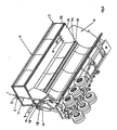
- the upper container body hoist 8 extends simultaneously keeping the hinged body top extension 4 (upper container body) in a horizontal orientation as it lifts via a connection to the body 25 and the hinged body top extension 4 through top hoist mount 5 and bottom hoist mount 15.
- the anti spill plate 10 is mounted to the body 25 to prevent product from leaking out the ends as the hinged body top extension 4 and the body 25 separate.
- the spill plate cover 19 prevents product from falling between the anti spill plate 10 and the hinged body top extension 4, the spill plate cover 19 can be made from a number of different materials such as metal, reinforced rubber or plastic.
- the retainer plate 2 holds pressure on the spill plate cover 19 to assist in the prevention of product falling behind the anti spill plate 10 by inserting pressure on the spill plate cover in the direction of the anti spill plate 10.
- the spill plate cover 19 can be removed through removing retainer plate bolts 18, the retainer plate 2 and the spill plate cover bolts 23 to assist in cleaning and maintenance of the anti spill plate 10.
- the hinged body top extension 4 is connected to the body 25 through a hinge mounting plate 20, top extension hinge bush 11 and top extension hinge pin 12 connected to the pipe body combing 21.
- the hinge seal lube plate 20 is made of plastic to aid in the lubrication of the hinge system and prevents product from leaking out through the side as the hinged body top extension 4 is raised.
- the hinge seal lube plate 20 is mounted to the hinged body top extension 4 and rotates around the pipe body combing 21 to ensure a continues seal between the hinged body top extension 4 and the pipe body combing 21.
- the safety strap 24 is used to prevent the hinged body top extension 4 coming away from the body 25 in the event of a rollover of the vehicle, a number of these are mounted along the body 25 under the pipe body combing 21 and welded to the hinged body top extension 4.
- a link arm 30 is operatively connected to the side door 32 by a link pivotable link member.
- the link arm operates via the link member to cooperatively open the side door to discharge a load to the side of the vehicle.
- the side door can act as a discharge ramp to ensure that material does not pile up immediately against the vehicle.
- figure 4 shows an alternative degree of opening 4a for the container.
- the upper container body is hingedly attached to the lower container body with the pivot axis below the link arm pivot point at each respective end of the container.
- the respective pivot axis is above the link arm 30 pivot point.
- Figure 5 shows an end view of the vehicle according to an embodiment of the present invention in a discharge position with main ram 26 extended thereby causing the lower container body to tip sideways with respect to the chassis 50.
- This causes the link arm 30, via link member 31 to open the side discharge door 32.
- the curved base 25a of the lower container body assists discharge of material and also helps avoid need for a liquid catchment sump.
- the secondary ram 8 operates to raise and pivot the upper container body 4 with respect to the lower container body.
- Optional end anti spill plates 10 restrict material from discharging out of the ends of the container.
- Spill plate covers 19 can be provided to protect the end anti spill plates from the load, and are preferably made or include flexible material, such as plastics, synthetic, polymeric, rubber or like materials. Closure of the container to a transport orientation can be the opposite of the opening procedure.
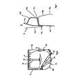
- Figure 6 shows the container, without chassis, in a closed orientation.
- Figure 7 shows portion 'B' in more detail, with the side door 32 including an inner wall portion 44 abutting at a top portion thereof a portion of the side wall 42 of the upper container'body 4.
- the outer wall portion 42 of the upper container body includes an abutment portion 46 against which the side door closes.
- This includes a reinforcing member 40 which also provides an upper sloped portion 47 to prevent build up of dirt, material and allow water runoff from the container.
- FIG 8 shows detail 'A' of a hinge arrangement between the upper and lower body portions.
- This includes a hinge seal 20 and lube plate 20, preferably formed of or including polymeric, plastics, rubber, synthetic or like materials.
- the main ram 25 pivots at an upper end thereof via a main ram upper pivot 61.
- the upper and lower container bodies can be operated by hydraulic cylinders. These cylinders can be controlled via one or more control valves, such as a double bank pressure compensating flow control valve. For example, when a "tip" cycle signal is sent to the valve(s) a specific volume of oil is sent to the lower container body lift cylinder(s) and a specific volume of oil is also sent to the upper container lift cylinder(s). Should the upper container body jam or the load be too great for the upper container body lift cylinder(s) to push, the valve spool will unload and the upper container lift cylinder(s) will stall while the lower container cylinder(s) will continue to tilt the lower container resulting in the whole vehicle tipping over.
- a control valves such as a double bank pressure compensating flow control valve.
- another valve may be provided in the system so that when the upper container body cylinder(s) are fully extended they depress a roller plunger on the DCV stopping the pilot signal from reaching the sequence valve and allow the upper container body to be fully open before the main lift cylinder(s) have reached end of stroke and allow the main lift cylinder(s) to keep extending.
- the container body with upper and lower container body portions is shown mounted to a chassis for a road vehicle.
- a chassis for a road vehicle may incorporate the present invention in one or more of its various forms, such as for rail or water craft transport.
- the present invention can advantageously be generally directed to be used on a vehicle side tipper system utilizing a bowl floor design to aid in the prevention of wet product leakage onto the ground without the use of a separate sump system for hauling and unloading high volume low density products.
Landscapes
- Engineering & Computer Science (AREA)
- Transportation (AREA)
- Mechanical Engineering (AREA)
- Refuse-Collection Vehicles (AREA)
- Auxiliary Methods And Devices For Loading And Unloading (AREA)
- Handcart (AREA)
- Refuse Receptacles (AREA)
- Medicines Containing Plant Substances (AREA)
- Processes Of Treating Macromolecular Substances (AREA)
- Glass Compositions (AREA)
Priority Applications (2)
| Application Number | Priority Date | Filing Date | Title |
|---|---|---|---|
| PL08850255T PL2214929T3 (pl) | 2007-11-15 | 2008-11-13 | Pojazd do transportu materiałów sypkich |
| SI200830796T SI2214929T1 (sl) | 2007-11-15 | 2008-11-13 | Vozilo za rokovanje s sipkim tovorom |
Applications Claiming Priority (2)
| Application Number | Priority Date | Filing Date | Title |
|---|---|---|---|
| AU2007906264A AU2007906264A0 (en) | 2007-11-15 | Bulk material handling vehicle | |
| PCT/AU2008/001690 WO2009062250A1 (en) | 2007-11-15 | 2008-11-13 | Bulk material handling vehicle |
Publications (3)
| Publication Number | Publication Date |
|---|---|
| EP2214929A1 EP2214929A1 (en) | 2010-08-11 |
| EP2214929A4 EP2214929A4 (en) | 2010-12-22 |
| EP2214929B1 true EP2214929B1 (en) | 2012-08-15 |
Family
ID=40638248
Family Applications (1)
| Application Number | Title | Priority Date | Filing Date |
|---|---|---|---|
| EP08850255A Not-in-force EP2214929B1 (en) | 2007-11-15 | 2008-11-13 | Bulk material handling vehicle |
Country Status (16)
| Country | Link |
|---|---|
| US (1) | US8708420B2 (da) |
| EP (1) | EP2214929B1 (da) |
| CN (1) | CN101868373B (da) |
| AU (1) | AU2008323620B2 (da) |
| CA (1) | CA2704876C (da) |
| DK (1) | DK2214929T3 (da) |
| ES (1) | ES2391361T3 (da) |
| HR (1) | HRP20120855T1 (da) |
| MX (1) | MX2010005312A (da) |
| NZ (1) | NZ585227A (da) |
| PL (1) | PL2214929T3 (da) |
| PT (1) | PT2214929E (da) |
| SI (1) | SI2214929T1 (da) |
| TW (1) | TW200932584A (da) |
| WO (1) | WO2009062250A1 (da) |
| ZA (1) | ZA201003543B (da) |
Families Citing this family (10)
| Publication number | Priority date | Publication date | Assignee | Title |
|---|---|---|---|---|
| WO2012063146A1 (en) * | 2010-11-09 | 2012-05-18 | Johannes Petrus Kotze | Transport of materials |
| US20160318434A1 (en) * | 2013-12-24 | 2016-11-03 | Air Tip Pty Ltd | Trailer door linkage |
| PL2949397T3 (pl) * | 2014-05-26 | 2017-05-31 | Sandvik Intellectual Property Ab | Składany zasobnik |
| US20190217765A1 (en) * | 2016-08-25 | 2019-07-18 | Volvo Construction Equipment Ab | Working machine |
| JP6612210B2 (ja) * | 2016-12-26 | 2019-11-27 | 本田技研工業株式会社 | 作業機 |
| RU2692289C1 (ru) * | 2018-07-27 | 2019-06-24 | Федеральное государственное бюджетное научное учреждение "Федеральный научный агроинженерный центр ВИМ" (ФГБНУ ФНАЦ ВИМ) | Контейнеровоз |
| AU2020276749B2 (en) | 2019-05-15 | 2026-02-19 | Lusty Tip Trailers Pty Ltd | Side tipper system |
| CN110588883B (zh) * | 2019-08-30 | 2020-09-18 | 中船澄西船舶修造有限公司 | 一种具有良好安全性的兼装谷物型木屑船的设计方法 |
| AU2024341479A1 (en) * | 2023-09-13 | 2026-03-26 | Roadwest Transport Equipment & Sales Pty Ltd | Side tipping trailer, and door assembly |
| CN119527744B (zh) * | 2024-12-20 | 2025-09-16 | 长沙中联重科环境产业有限公司 | 垃圾箱和转运设备 |
Family Cites Families (15)
| Publication number | Priority date | Publication date | Assignee | Title |
|---|---|---|---|---|
| US2072998A (en) * | 1935-05-03 | 1937-03-09 | Isaacson Iron Works Inc | Load hauling vehicle |
| US2870923A (en) * | 1957-05-23 | 1959-01-27 | Jr Lisle A Jewell | Convertible dump body |
| US3687321A (en) | 1970-03-24 | 1972-08-29 | Stanray Corp | Load carrying vehicle |
| US3799612A (en) | 1972-09-22 | 1974-03-26 | Titan Trailer Corp | Box hold down system |
| US4113120A (en) * | 1977-02-22 | 1978-09-12 | Pickrell John W | Container handling and transporting apparatus |
| US4619484A (en) * | 1984-09-17 | 1986-10-28 | Maxey John H | Side unloading dump truck |
| US4666211A (en) | 1985-04-12 | 1987-05-19 | Smith Gavin C | Multi-level transport truck apparatus |
| US4930297A (en) * | 1988-10-11 | 1990-06-05 | Deere & Company | Telescoping basket for a cotton harvester |
| US5006039A (en) | 1989-06-14 | 1991-04-09 | Toter, Inc. | Method of emptying a container |
| US5299856A (en) | 1991-05-17 | 1994-04-05 | Richardton Manufacturing Company (Div. Of Core) | Dump vehicle with hydraulic lock for material holding container |
| WO1994026630A1 (en) | 1993-05-06 | 1994-11-24 | Nikita Victor Vinocuroff | Container handling system |
| US6428264B1 (en) * | 2000-04-14 | 2002-08-06 | Thurston Mfg. Co. | Side dump body including a material compaction assembly |
| US7722125B1 (en) * | 2005-05-26 | 2010-05-25 | Black Swamp Industries, Inc. | Displacement actuated side dumping haul body |
| CN2880585Y (zh) * | 2005-12-23 | 2007-03-21 | 柳州特种汽车厂 | 侧翻自卸汽车车门开合装置 |
| CN2892559Y (zh) * | 2006-05-04 | 2007-04-25 | 张海军 | 自卸无碍车厢 |
-
2008
- 2008-11-13 EP EP08850255A patent/EP2214929B1/en not_active Not-in-force
- 2008-11-13 WO PCT/AU2008/001690 patent/WO2009062250A1/en not_active Ceased
- 2008-11-13 DK DK08850255.4T patent/DK2214929T3/da active
- 2008-11-13 NZ NZ585227A patent/NZ585227A/en unknown
- 2008-11-13 SI SI200830796T patent/SI2214929T1/sl unknown
- 2008-11-13 CN CN2008801164764A patent/CN101868373B/zh not_active Expired - Fee Related
- 2008-11-13 PL PL08850255T patent/PL2214929T3/pl unknown
- 2008-11-13 CA CA2704876A patent/CA2704876C/en not_active Expired - Fee Related
- 2008-11-13 AU AU2008323620A patent/AU2008323620B2/en active Active
- 2008-11-13 MX MX2010005312A patent/MX2010005312A/es active IP Right Grant
- 2008-11-13 HR HRP20120855AT patent/HRP20120855T1/hr unknown
- 2008-11-13 PT PT08850255T patent/PT2214929E/pt unknown
- 2008-11-13 US US12/742,253 patent/US8708420B2/en active Active
- 2008-11-13 ES ES08850255T patent/ES2391361T3/es active Active
- 2008-11-14 TW TW097144139A patent/TW200932584A/zh unknown
-
2010
- 2010-05-19 ZA ZA2010/03543A patent/ZA201003543B/en unknown
Also Published As
| Publication number | Publication date |
|---|---|
| MX2010005312A (es) | 2010-09-09 |
| SI2214929T1 (sl) | 2012-12-31 |
| CA2704876C (en) | 2017-06-20 |
| CA2704876A1 (en) | 2009-05-22 |
| US8708420B2 (en) | 2014-04-29 |
| EP2214929A4 (en) | 2010-12-22 |
| AU2008323620A1 (en) | 2009-05-22 |
| HRP20120855T1 (hr) | 2012-11-30 |
| ES2391361T3 (es) | 2012-11-23 |
| CN101868373A (zh) | 2010-10-20 |
| CN101868373B (zh) | 2012-11-28 |
| WO2009062250A1 (en) | 2009-05-22 |
| AU2008323620B2 (en) | 2013-09-05 |
| US20100308638A1 (en) | 2010-12-09 |
| PT2214929E (pt) | 2012-10-25 |
| PL2214929T3 (pl) | 2013-01-31 |
| ZA201003543B (en) | 2011-03-30 |
| TW200932584A (en) | 2009-08-01 |
| NZ585227A (en) | 2011-09-30 |
| DK2214929T3 (da) | 2012-11-05 |
| EP2214929A1 (en) | 2010-08-11 |
Similar Documents
| Publication | Publication Date | Title |
|---|---|---|
| EP2214929B1 (en) | Bulk material handling vehicle | |
| US6722839B2 (en) | Refuse collection body | |
| US5316430A (en) | Material collecting and hauling apparatus | |
| US5035564A (en) | Truck body construction for separate handling of re-cyclable refuse | |
| US6146079A (en) | Dual blade packer system for refuse collection vehicle | |
| US6234739B1 (en) | Compaction mechanism for refuse and recyclables collection vehicles | |
| RU2119883C1 (ru) | Транспортное средство для приема и транспортировки мусора | |
| US20030202870A1 (en) | Refuse collection vehicle with pendular packing device and refuse ejection system | |
| US6938960B1 (en) | Top-loading container and cover assembly for collecting, storing, handling, and transporting bulk materials | |
| US6761414B1 (en) | Top hinged gravity, floating and power self-opening gate for dump body | |
| US20020000748A1 (en) | Vehicle for depositing dry and liquid material | |
| CN114030793B (zh) | 一种分体式垃圾压缩站及系统 | |
| CN101495360B (zh) | 机械后挡板 | |
| CN214827443U (zh) | 一种散料卸船用料仓 | |
| CN210794486U (zh) | 一种垃圾分类压缩转运车 | |
| CN207791770U (zh) | 一种设有智能化卸料联动系统的吊装式垃圾压缩车 | |
| US2943754A (en) | Vehicular dumping receptacle | |
| AU637599B2 (en) | Apparatus for loading material into a storage compartment | |
| CN206766880U (zh) | 一种设有智能化进料联动系统的吊装式垃圾压缩车 | |
| WO1997033768A1 (en) | Improved bulk material handling vehicle | |
| CN206766879U (zh) | 一种设有进料口开盖装置的吊装式垃圾压缩车 | |
| CN207551077U (zh) | 一种设有弧形后门的吊装式垃圾压缩车 | |
| CN207375124U (zh) | 一种吊装压实推卸垃圾运输车 | |
| WO1998050295A1 (en) | Refuse collection vehicle | |
| JP7572769B2 (ja) | 塵芥収集車 |
Legal Events
| Date | Code | Title | Description |
|---|---|---|---|
| PUAI | Public reference made under article 153(3) epc to a published international application that has entered the european phase |
Free format text: ORIGINAL CODE: 0009012 |
|
| 17P | Request for examination filed |
Effective date: 20100527 |
|
| AK | Designated contracting states |
Kind code of ref document: A1 Designated state(s): AT BE BG CH CY CZ DE DK EE ES FI FR GB GR HR HU IE IS IT LI LT LU LV MC MT NL NO PL PT RO SE SI SK TR |
|
| AX | Request for extension of the european patent |
Extension state: AL BA MK RS |
|
| A4 | Supplementary search report drawn up and despatched |
Effective date: 20101119 |
|
| DAX | Request for extension of the european patent (deleted) | ||
| 17Q | First examination report despatched |
Effective date: 20110817 |
|
| GRAP | Despatch of communication of intention to grant a patent |
Free format text: ORIGINAL CODE: EPIDOSNIGR1 |
|
| GRAS | Grant fee paid |
Free format text: ORIGINAL CODE: EPIDOSNIGR3 |
|
| GRAA | (expected) grant |
Free format text: ORIGINAL CODE: 0009210 |
|
| AK | Designated contracting states |
Kind code of ref document: B1 Designated state(s): AT BE BG CH CY CZ DE DK EE ES FI FR GB GR HR HU IE IS IT LI LT LU LV MC MT NL NO PL PT RO SE SI SK TR |
|
| RAP1 | Party data changed (applicant data changed or rights of an application transferred) |
Owner name: MAXITRANS AUSTRALIA PTY LTD. |
|
| REG | Reference to a national code |
Ref country code: AT Ref legal event code: REF Ref document number: 570632 Country of ref document: AT Kind code of ref document: T Effective date: 20120815 Ref country code: CH Ref legal event code: EP Ref country code: GB Ref legal event code: FG4D |
|
| RIN1 | Information on inventor provided before grant (corrected) |
Inventor name: BERND OSTERMEYER |
|
| REG | Reference to a national code |
Ref country code: IE Ref legal event code: FG4D |
|
| REG | Reference to a national code |
Ref country code: DE Ref legal event code: R096 Ref document number: 602008018106 Country of ref document: DE Effective date: 20121011 |
|
| REG | Reference to a national code |
Ref country code: CH Ref legal event code: NV Representative=s name: MEYER & KOLLEGEN |
|
| REG | Reference to a national code |
Ref country code: HR Ref legal event code: TUEP Ref document number: P20120855 Country of ref document: HR |
|
| REG | Reference to a national code |
Ref country code: RO Ref legal event code: EPE |
|
| REG | Reference to a national code |
Ref country code: PT Ref legal event code: SC4A Free format text: AVAILABILITY OF NATIONAL TRANSLATION Effective date: 20121017 |
|
| REG | Reference to a national code |
Ref country code: DK Ref legal event code: T3 |
|
| REG | Reference to a national code |
Ref country code: SE Ref legal event code: TRGR |
|
| REG | Reference to a national code |
Ref country code: NL Ref legal event code: T3 |
|
| REG | Reference to a national code |
Ref country code: ES Ref legal event code: FG2A Ref document number: 2391361 Country of ref document: ES Kind code of ref document: T3 Effective date: 20121123 |
|
| REG | Reference to a national code |
Ref country code: HR Ref legal event code: T1PR Ref document number: P20120855 Country of ref document: HR |
|
| REG | Reference to a national code |
Ref country code: NO Ref legal event code: T2 Effective date: 20120815 |
|
| PG25 | Lapsed in a contracting state [announced via postgrant information from national office to epo] |
Ref country code: IS Free format text: LAPSE BECAUSE OF FAILURE TO SUBMIT A TRANSLATION OF THE DESCRIPTION OR TO PAY THE FEE WITHIN THE PRESCRIBED TIME-LIMIT Effective date: 20121215 |
|
| REG | Reference to a national code |
Ref country code: PL Ref legal event code: T3 |
|
| REG | Reference to a national code |
Ref country code: SK Ref legal event code: T3 Ref document number: E 12850 Country of ref document: SK |
|
| REG | Reference to a national code |
Ref country code: EE Ref legal event code: FG4A Ref document number: E007354 Country of ref document: EE Effective date: 20121107 |
|
| REG | Reference to a national code |
Ref country code: GR Ref legal event code: EP Ref document number: 20120402526 Country of ref document: GR Effective date: 20130122 |
|
| PLBE | No opposition filed within time limit |
Free format text: ORIGINAL CODE: 0009261 |
|
| STAA | Information on the status of an ep patent application or granted ep patent |
Free format text: STATUS: NO OPPOSITION FILED WITHIN TIME LIMIT |
|
| 26N | No opposition filed |
Effective date: 20130516 |
|
| PG25 | Lapsed in a contracting state [announced via postgrant information from national office to epo] |
Ref country code: CY Free format text: LAPSE BECAUSE OF NON-PAYMENT OF DUE FEES Effective date: 20121113 |
|
| REG | Reference to a national code |
Ref country code: DE Ref legal event code: R097 Ref document number: 602008018106 Country of ref document: DE Effective date: 20130516 |
|
| REG | Reference to a national code |
Ref country code: HU Ref legal event code: AG4A Ref document number: E016749 Country of ref document: HU |
|
| PG25 | Lapsed in a contracting state [announced via postgrant information from national office to epo] |
Ref country code: MT Free format text: LAPSE BECAUSE OF FAILURE TO SUBMIT A TRANSLATION OF THE DESCRIPTION OR TO PAY THE FEE WITHIN THE PRESCRIBED TIME-LIMIT Effective date: 20120815 |
|
| PG25 | Lapsed in a contracting state [announced via postgrant information from national office to epo] |
Ref country code: MC Free format text: LAPSE BECAUSE OF NON-PAYMENT OF DUE FEES Effective date: 20121130 |
|
| PG25 | Lapsed in a contracting state [announced via postgrant information from national office to epo] |
Ref country code: LU Free format text: LAPSE BECAUSE OF NON-PAYMENT OF DUE FEES Effective date: 20121113 |
|
| REG | Reference to a national code |
Ref country code: FR Ref legal event code: PLFP Year of fee payment: 8 |
|
| REG | Reference to a national code |
Ref country code: FR Ref legal event code: PLFP Year of fee payment: 9 |
|
| REG | Reference to a national code |
Ref country code: HR Ref legal event code: ODRP Ref document number: P20120855 Country of ref document: HR Payment date: 20171102 Year of fee payment: 10 |
|
| REG | Reference to a national code |
Ref country code: FR Ref legal event code: PLFP Year of fee payment: 10 |
|
| PGFP | Annual fee paid to national office [announced via postgrant information from national office to epo] |
Ref country code: DE Payment date: 20171122 Year of fee payment: 10 Ref country code: NO Payment date: 20171115 Year of fee payment: 10 Ref country code: FR Payment date: 20171128 Year of fee payment: 10 Ref country code: HU Payment date: 20171102 Year of fee payment: 10 Ref country code: NL Payment date: 20171120 Year of fee payment: 10 Ref country code: RO Payment date: 20171106 Year of fee payment: 10 Ref country code: SK Payment date: 20171110 Year of fee payment: 10 Ref country code: TR Payment date: 20171113 Year of fee payment: 10 Ref country code: EE Payment date: 20171113 Year of fee payment: 10 Ref country code: LT Payment date: 20171109 Year of fee payment: 10 Ref country code: FI Payment date: 20171116 Year of fee payment: 10 Ref country code: DK Payment date: 20171114 Year of fee payment: 10 Ref country code: CZ Payment date: 20171103 Year of fee payment: 10 |
|
| PGFP | Annual fee paid to national office [announced via postgrant information from national office to epo] |
Ref country code: PT Payment date: 20171106 Year of fee payment: 10 Ref country code: IE Payment date: 20171127 Year of fee payment: 10 Ref country code: CH Payment date: 20171120 Year of fee payment: 10 Ref country code: IT Payment date: 20171114 Year of fee payment: 10 Ref country code: GB Payment date: 20171127 Year of fee payment: 10 Ref country code: SI Payment date: 20171108 Year of fee payment: 10 Ref country code: SE Payment date: 20171115 Year of fee payment: 10 Ref country code: PL Payment date: 20171103 Year of fee payment: 10 Ref country code: AT Payment date: 20171124 Year of fee payment: 10 Ref country code: BG Payment date: 20171116 Year of fee payment: 10 Ref country code: BE Payment date: 20171110 Year of fee payment: 10 Ref country code: LV Payment date: 20171127 Year of fee payment: 10 Ref country code: GR Payment date: 20171130 Year of fee payment: 10 Ref country code: HR Payment date: 20171102 Year of fee payment: 10 |
|
| PGFP | Annual fee paid to national office [announced via postgrant information from national office to epo] |
Ref country code: ES Payment date: 20180221 Year of fee payment: 10 |
|
| REG | Reference to a national code |
Ref country code: HR Ref legal event code: PBON Ref document number: P20120855 Country of ref document: HR Effective date: 20181113 |
|
| REG | Reference to a national code |
Ref country code: DE Ref legal event code: R119 Ref document number: 602008018106 Country of ref document: DE |
|
| REG | Reference to a national code |
Ref country code: LT Ref legal event code: MM4D Effective date: 20181113 |
|
| REG | Reference to a national code |
Ref country code: EE Ref legal event code: MM4A Ref document number: E007354 Country of ref document: EE Effective date: 20181130 |
|
| REG | Reference to a national code |
Ref country code: DK Ref legal event code: EBP Effective date: 20181130 Ref country code: NO Ref legal event code: MMEP |
|
| REG | Reference to a national code |
Ref country code: CH Ref legal event code: PL |
|
| REG | Reference to a national code |
Ref country code: SE Ref legal event code: EUG |
|
| REG | Reference to a national code |
Ref country code: NL Ref legal event code: MM Effective date: 20181201 |
|
| REG | Reference to a national code |
Ref country code: AT Ref legal event code: MM01 Ref document number: 570632 Country of ref document: AT Kind code of ref document: T Effective date: 20181113 |
|
| GBPC | Gb: european patent ceased through non-payment of renewal fee |
Effective date: 20181113 |
|
| PG25 | Lapsed in a contracting state [announced via postgrant information from national office to epo] |
Ref country code: NO Free format text: LAPSE BECAUSE OF NON-PAYMENT OF DUE FEES Effective date: 20181130 Ref country code: PT Free format text: LAPSE BECAUSE OF NON-PAYMENT OF DUE FEES Effective date: 20190513 Ref country code: FI Free format text: LAPSE BECAUSE OF NON-PAYMENT OF DUE FEES Effective date: 20181113 Ref country code: SE Free format text: LAPSE BECAUSE OF NON-PAYMENT OF DUE FEES Effective date: 20181114 Ref country code: CZ Free format text: LAPSE BECAUSE OF NON-PAYMENT OF DUE FEES Effective date: 20181113 Ref country code: LT Free format text: LAPSE BECAUSE OF NON-PAYMENT OF DUE FEES Effective date: 20181113 |
|
| REG | Reference to a national code |
Ref country code: SK Ref legal event code: MM4A Ref document number: E 12850 Country of ref document: SK Effective date: 20181113 |
|
| REG | Reference to a national code |
Ref country code: BE Ref legal event code: MM Effective date: 20181130 |
|
| REG | Reference to a national code |
Ref country code: IE Ref legal event code: MM4A |
|
| PG25 | Lapsed in a contracting state [announced via postgrant information from national office to epo] |
Ref country code: SK Free format text: LAPSE BECAUSE OF NON-PAYMENT OF DUE FEES Effective date: 20181113 Ref country code: CH Free format text: LAPSE BECAUSE OF NON-PAYMENT OF DUE FEES Effective date: 20181130 Ref country code: BG Free format text: LAPSE BECAUSE OF NON-PAYMENT OF DUE FEES Effective date: 20190531 Ref country code: LV Free format text: LAPSE BECAUSE OF NON-PAYMENT OF DUE FEES Effective date: 20181113 Ref country code: HR Free format text: LAPSE BECAUSE OF NON-PAYMENT OF DUE FEES Effective date: 20181113 Ref country code: EE Free format text: LAPSE BECAUSE OF NON-PAYMENT OF DUE FEES Effective date: 20181130 Ref country code: HU Free format text: LAPSE BECAUSE OF NON-PAYMENT OF DUE FEES Effective date: 20181114 Ref country code: GR Free format text: LAPSE BECAUSE OF NON-PAYMENT OF DUE FEES Effective date: 20190605 Ref country code: RO Free format text: LAPSE BECAUSE OF NON-PAYMENT OF DUE FEES Effective date: 20181113 Ref country code: SI Free format text: LAPSE BECAUSE OF NON-PAYMENT OF DUE FEES Effective date: 20181114 Ref country code: NL Free format text: LAPSE BECAUSE OF NON-PAYMENT OF DUE FEES Effective date: 20181201 Ref country code: LI Free format text: LAPSE BECAUSE OF NON-PAYMENT OF DUE FEES Effective date: 20181130 |
|
| REG | Reference to a national code |
Ref country code: SI Ref legal event code: KO00 Effective date: 20190709 |
|
| PG25 | Lapsed in a contracting state [announced via postgrant information from national office to epo] |
Ref country code: DE Free format text: LAPSE BECAUSE OF NON-PAYMENT OF DUE FEES Effective date: 20190601 Ref country code: FR Free format text: LAPSE BECAUSE OF NON-PAYMENT OF DUE FEES Effective date: 20181130 Ref country code: AT Free format text: LAPSE BECAUSE OF NON-PAYMENT OF DUE FEES Effective date: 20181113 Ref country code: IE Free format text: LAPSE BECAUSE OF NON-PAYMENT OF DUE FEES Effective date: 20181113 Ref country code: DK Free format text: LAPSE BECAUSE OF NON-PAYMENT OF DUE FEES Effective date: 20181130 Ref country code: IT Free format text: LAPSE BECAUSE OF NON-PAYMENT OF DUE FEES Effective date: 20181113 |
|
| PG25 | Lapsed in a contracting state [announced via postgrant information from national office to epo] |
Ref country code: BE Free format text: LAPSE BECAUSE OF NON-PAYMENT OF DUE FEES Effective date: 20181130 |
|
| PG25 | Lapsed in a contracting state [announced via postgrant information from national office to epo] |
Ref country code: GB Free format text: LAPSE BECAUSE OF NON-PAYMENT OF DUE FEES Effective date: 20181113 |
|
| REG | Reference to a national code |
Ref country code: ES Ref legal event code: FD2A Effective date: 20200103 |
|
| PG25 | Lapsed in a contracting state [announced via postgrant information from national office to epo] |
Ref country code: ES Free format text: LAPSE BECAUSE OF NON-PAYMENT OF DUE FEES Effective date: 20181114 |
|
| PG25 | Lapsed in a contracting state [announced via postgrant information from national office to epo] |
Ref country code: PL Free format text: LAPSE BECAUSE OF NON-PAYMENT OF DUE FEES Effective date: 20181113 |
|
| PG25 | Lapsed in a contracting state [announced via postgrant information from national office to epo] |
Ref country code: TR Free format text: LAPSE BECAUSE OF NON-PAYMENT OF DUE FEES Effective date: 20181113 |