EP2215638B1 - Système de transfert de cartouche comprenant une cloche blindée à déplacement indépendant - Google Patents
Système de transfert de cartouche comprenant une cloche blindée à déplacement indépendant Download PDFInfo
- Publication number
- EP2215638B1 EP2215638B1 EP08842220.9A EP08842220A EP2215638B1 EP 2215638 B1 EP2215638 B1 EP 2215638B1 EP 08842220 A EP08842220 A EP 08842220A EP 2215638 B1 EP2215638 B1 EP 2215638B1
- Authority
- EP
- European Patent Office
- Prior art keywords
- trolley
- transfer system
- canister
- pair
- spaced
- Prior art date
- Legal status (The legal status is an assumption and is not a legal conclusion. Google has not performed a legal analysis and makes no representation as to the accuracy of the status listed.)
- Active
Links
Images




Classifications
-
- G—PHYSICS
- G21—NUCLEAR PHYSICS; NUCLEAR ENGINEERING
- G21C—NUCLEAR REACTORS
- G21C19/00—Arrangements for treating, for handling, or for facilitating the handling of, fuel or other materials which are used within the reactor, e.g. within its pressure vessel
- G21C19/32—Apparatus for removing radioactive objects or materials from the reactor discharge area, e.g. to a storage place; Apparatus for handling radioactive objects or materials within a storage place or removing them therefrom
-
- B—PERFORMING OPERATIONS; TRANSPORTING
- B66—HOISTING; LIFTING; HAULING
- B66C—CRANES; LOAD-ENGAGING ELEMENTS OR DEVICES FOR CRANES, CAPSTANS, WINCHES, OR TACKLES
- B66C17/00—Overhead travelling cranes comprising one or more substantially horizontal girders the ends of which are directly supported by wheels or rollers running on tracks carried by spaced supports
-
- G—PHYSICS
- G21—NUCLEAR PHYSICS; NUCLEAR ENGINEERING
- G21C—NUCLEAR REACTORS
- G21C19/00—Arrangements for treating, for handling, or for facilitating the handling of, fuel or other materials which are used within the reactor, e.g. within its pressure vessel
- G21C19/02—Details of handling arrangements
-
- G—PHYSICS
- G21—NUCLEAR PHYSICS; NUCLEAR ENGINEERING
- G21C—NUCLEAR REACTORS
- G21C19/00—Arrangements for treating, for handling, or for facilitating the handling of, fuel or other materials which are used within the reactor, e.g. within its pressure vessel
- G21C19/02—Details of handling arrangements
- G21C19/10—Lifting devices or pulling devices adapted for co-operation with fuel elements or with control elements
-
- G—PHYSICS
- G21—NUCLEAR PHYSICS; NUCLEAR ENGINEERING
- G21F—PROTECTION AGAINST X-RADIATION, GAMMA RADIATION, CORPUSCULAR RADIATION OR PARTICLE BOMBARDMENT; TREATING RADIOACTIVELY CONTAMINATED MATERIAL; DECONTAMINATION ARRANGEMENTS THEREFOR
- G21F5/00—Transportable or portable shielded containers
- G21F5/06—Details of, or accessories to, the containers
- G21F5/14—Devices for handling containers or shipping-casks, e.g. transporting devices loading and unloading, filling of containers
-
- Y—GENERAL TAGGING OF NEW TECHNOLOGICAL DEVELOPMENTS; GENERAL TAGGING OF CROSS-SECTIONAL TECHNOLOGIES SPANNING OVER SEVERAL SECTIONS OF THE IPC; TECHNICAL SUBJECTS COVERED BY FORMER USPC CROSS-REFERENCE ART COLLECTIONS [XRACs] AND DIGESTS
- Y02—TECHNOLOGIES OR APPLICATIONS FOR MITIGATION OR ADAPTATION AGAINST CLIMATE CHANGE
- Y02E—REDUCTION OF GREENHOUSE GAS [GHG] EMISSIONS, RELATED TO ENERGY GENERATION, TRANSMISSION OR DISTRIBUTION
- Y02E30/00—Energy generation of nuclear origin
- Y02E30/30—Nuclear fission reactors
Definitions
- the field of the present invention generally relates to overhead hoist or crane systems and, more particularly, to such systems for transporting canisters of spent nuclear fuel.
- Spent nuclear fuel is typically transferred in canisters which are moved by overhead hoist or crane systems.
- canisters which are moved by overhead hoist or crane systems.
- the spent nuclear fuel remains highly radioactive and is capable of generating significant thermal energy. Therefore, the canisters are typically transferred within a shielded bell.
- a transfer system for moving a spent fuel canister comprises, in combination, a carrier, a shielded bell, a shielded bell trolley movable along the carrier and carrying a shielded bell, and a canister trolley movable along the carrier and carrying a lifting mechanism for raising and lowering the spent fuel canister into and out of the shielded bell.
- the canister trolley can move along the carrier independent of the shielded bell trolley.
- An interlock is provided for selectively interlocking the canister trolley with the shielded bell trolley so that the canister trolley and the shielded bell trolley move together along the carrier.
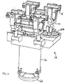
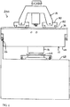
- FIGS. 1 and 2 shows a canister transfer system 10 according to a preferred embodiment of the present invention.
- the operating envelope of the illustrated canister transfer system 10 provides coverage of a transportation cask transfer cell, waste package transfer cell, canister staging cells, and transfer system maintenance/staging area.
- the illustrated canister transfer system 10 includes a carrier 12, a first or shielded bell trolley 14 movable along the carrier 12 and carrying a shielded bell 14, and a second or canister trolley 18 movable along the carrier 12 and carrying a lifting mechanism 20 for raising and lowering the spent fuel canister 22 (see figure 9 ) into and out of the shielded bell.
- the illustrated canister transfer system 10 is in the form of a bridge crane, wherein the carrier 12 in the form of a bridge 24. It is noted that the canister transfer system 10 can alternatively have any other suitable form and/or the carrier 12 can alternatively have any other suitable form.
- the illustrated bridge 24 includes end trucks riding on a pair of laterally spaced apart and parallel rails 26.
- the illustrated rails 26 are straight but it is noted that any other suitable configuration for the rails 26 can be utilized.
- the illustrated rails 26 supported by corbels 28 located on laterally spaced-apart walls 30. It is noted that any other suitable supports for the rails 26 can alternatively be utilized.
- the distance between the rails 26 can be any suitable distance such as, for example, about eighty six feet.
- the illustrated bridge 24 is formed by box frame girders 32. Girder plates may be continuously welded for maximum strength, stiffness, and torsional stability but can alternatively be constructed in any other suitable manner. Bumpers 34 are provided at the ends of the rails 26 which are designed to minimize impact to the canisters 22 being transferred. Each bridge girder 32 supports the two trolleys 14, 18. A first or inner pair of rails 36 is provided for the canister trolley 18 and a second or outer pair of rails 38 is provided for the shielded bell trolley 14. The rails 36, 38 may be fastened to the girders 32 with welded clips but can alternatively be secured in any other suitable manner.
- the rails 36, 38 are mounted on top of the girders 32 so that the bridge 24 directly and independently supports each of the two trolleys 14, 18.
- the illustrated first pair of spaced-apart rails 36 is substantially parallel to the second pair of spaced-apart rails 38.
- the illustrated first and second pairs of rails 36, 38 extend in the lateral direction, that is along the longitudinal length of the bridge 24, such that the first and second pairs of rails 36, 38 are substantially perpendicular to the rails 26 for the bridge 24.
- the illustrated first and second pairs of rails 36, 38 are each straight but it is noted that any other suitable configuration for the rails 36, 38 can be utilized.
- the illustrated first and second pairs of rails 36, 38 are located at the same height but can alternatively be located at other heights as described in more detail hereinafter.
- the canister or main hoist trolley 18 includes a frame or body 40 having a plurality of wheels 42 which cooperate with the rails 36 so that the canister trolley 18 can be selectively moved along the rails 36.
- the canister trolley 18 can have any suitable type of drive mechanism for the wheels 42 such as, for example, an electric motor.
- the illustrated canister trolley 18 rides on the inner rails 36 of the bridge 24 and may be provided with seismic restraints.
- the canister trolley 18 also includes the lifting mechanism 20 for performing various transfer operations including raising and lowering the canisters 22.
- the illustrated lifting mechanism 20 is a crane or hoist system 44 having a remote grapple attachment or system 46. It is noted that any other suitable type of lifting mechanism 20 can alternatively be utilized.
- the crane or hoist 44 may utilize failure proof technology.
- the illustrated hoist 44 includes an upper block assembly 48 and a lower block assembly 50 that is suspended from the upper block assembly 52 by a reeving arrangement 52. Operation of an electric motor raises and lowers the lower block 50. Secured to the lower block assembly 50 is the grapple attachment 46 which is adapted to interact with the shielded bell 16 and the canisters 22 as described in more detail hereinafter.
- the remotely operated grapple attachment 46 may utilize limit switches to verify grapple engagement.
- the grapple attachment 46 may utilize a mechanism that includes a mechanical safe drive that will not allow the grapple attachment 46 to disengage when a load is suspended from the grapple attachment 46.
- the canister trolley 18 can have any suitable hoisting capacity such as, for example, seventy tons. Electrical power to the canister trolley 18 is provided through hard-wired connections using a cable track system.
- the illustrated shielded bell 16 is generally cylindrical shaped and has an inner wall 54 which forms an interior space or main shielding chamber 56.
- the illustrated shielded bell 16 has a pair of opposed lifting lugs or trunnions 58 near its top end which are used by the trolley 14 to hold the shielded bell 16.
- the shielded bell 16 can be formed of any suitable material such as, for example, steel and may reduce radiation exposure to operating personnel by limiting the contact dose rate (exterior of the shielded bell 16) to about one hundred mrems/hr.
- the total weight of the shielded bell 16 supported by the shielded bell trolley 14 can be, for example, about two hundred tons.
- the bottom end of the illustrated shielded bell 16 can be attached to a chamber 60 to accommodate cask lids having diameters of, for example, up to eighty-four inches.
- a bottom plate 62 with an opening can be attached to the chamber to support a motorized shield gate 64.
- the bottom plate 62 can have a thickness of, for example, about nine inches and the opening can have a diameter of, for example, about eighty six inches.
- the shield gate 64 can have a thickness of, for example, about twelve inches.
- the sliding shield gate 64 provides bottom shielding for the canister 22 once the canister 22 is inside the shielded bell 16.
- a shielded skirt 66 is provided around the perimeter of the bottom plate 62 which can be raised and lowered with the help of mechanical actuators.
- the shield skirt 66 is used to close any gap between the bottom plate 62 and a floor surface 68 to prevent any lateral radiation shine during a canister transfer operation.
- the shielded skirt 66 can have a thickness of, for example, about nine inches.
- the bottom plate 62 can be located about two inches above the concrete floor 68 where canister transfer ports are located.
- the shielded bell trolley 14 supports the shielded bell 16 and includes a frame of body 70 having a plurality of wheels72 which cooperate with the rails 38 so that the shielded bell trolley 14 can be selectively moved along the rails 38.
- the shielded bell trolley 14 can have any suitable type of drive mechanism for the wheels 72 such as, for example, an electric motor. Electrical power to the shielded bell trolley 14 is provided through hard-wired connections using a cable track system.
- the shielded bell trolley 14 also includes grapple means 74 for interacting with the shielded bell 16.
- the illustrated grapple means 74 is in the form of a pair of paddles secured directly to the trolley frame 70.
- the paddles 74 include openings for receiving the trunnions 58 of the shielded bell 16.
- grapple means 74 can alternatively be of any suitable type. It is also noted that if desired the shielded bell trolley 14 can alternatively include a crane or hoist such as that described in U.S. Patent Application Number 11/839,797 , the disclosure of which is expressly incorporated herein in its entirety by reference.
- the illustrated shielded bell trolley 14 rides on the outer rails 38 and supports the shielded bell 16 which includes the main shielding chamber 60 for shielding canisters 22, a lower larger chamber 76 for accommodating cask lids 78, and the slide gate 64 for providing bottom shielding for canisters 22 when inside the shielded chamber 60.
- the shielded bell trolley 14 carries the entire load of the shielded bell 16 and the bridge 24 directly supports the shielded bell trolley 14 so that the hoist system 44 of the canister trolley 18 is never required to support the shielded bell 16.
- the load path for the shielded bell 16 does not pass through the hoist system 44 or the canister trolley 18.
- the shielded bell trolley 14 may be provided with seismic restraints.
- the trunnion-type attachment of the shielded bell 16 to the shielded bell trolley 14 may form a a swivel type joint to minimize transmission of seismic load to the trolley frame 70.
- All hoist, trolley and bridge drive gearing may be enclosed in sealed gear boxes, with oil of high flash point such as four hundred degrees Fahrenheit or better, that will not support a flame or fire.
- Electric power is provided by a crane cable track system 80 located along the runway length and supported by the facility walls 30.
- the canister trolley 18, the hoist system 44, and the shielded bell trolley 14 may each be controlled from a control room with a local control station as a backup. Limit switches, load cells and interlocks may be provided for the operation of the two trolleys 14, 18.
- the illustrated canister transfer system 10 allows for the two trolleys 14, 18 to move independently of one another when desired and to be selectively interlocked together to operate as a single unit when performing selected canister transfer operations.
- the canister trolley 18 with the grapple 46 is first positioned concentric with the shielded bell 16, wherein the central axis of the grapple 46 is aligned with the central axis of the shielded bell 16.
- the two trolleys 14, 18 are mechanically interlocked locked prior to starting a canister transfer operation by lowering the grapple 46 into the shielded bell 16. It is noted that the trolleys 14, 18 can alternatively be mechanically interlocked in any other suitable means.
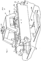
- FIGS. 3 to 5 illustrate a canister transfer system 100.
- the canister transfer system 100 illustrates that the shielded bell trolley 14 can be in an under running position. Either an over running or under running configuration can be utilized depending on the total allowable head room for the application.
- the illustrated rails 38 for the shielded bell trolley 14 are located outward and below the rails 36 for the canister trolley 18.
- the canister trolley 18 Located above the shielded bell trolley 14 is the canister trolley 18 which operates independently of the shielded bell trolley 14 and has a telescoping mast 102 with a universal nose that can be attached to various tools for the work that needs to be performed.
- a tool box 104 for the tools can be located at an end of the shielded bell trolley 14.
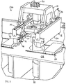
- FIGS. 6 to 9 illustrate a transfer system 200 according to a second embodiment of the present invention.
- the canister transfer system 200 illustrates that the shielded bell trolley 14 can be located inward of the canister trolley 18.
- the illustrated rails 38 for the shielded bell trolley 14 are located inward and below the rails 36 for the canister trolley 18.
- Located above the shielded bell trolley 14 is the canister trolley 18 which operates independently of the shielded bell trolley 14.
- a typical canister transfer operation using the canister transfer system 10, 100, 200 includes positioning the shielded bell 16 over a port on a concrete deck or floor 68 with the shielded bell bottom being about two inches above the deck 68.
- Below the concrete deck 68 is a shielded transfer cell 76 with the port located above a loaded storage cask 82.
- an empty waste package is positioned under an adjacent port of the waste package transfer cell.
- Each port is equipped with a motorized shielded gate and flushed with concrete deck surface.
- the transfer operation typically begins by positioning the canister transfer system 10 over the port with the loaded storage cask 82.
- the shield skirt 66 is remotely lowered to rest on the deck 68 to prevent any lateral radiation shine.
- the shielded slide gate 84 on the concrete deck 68 is opened to access the cask lid 78 located below.
- the slide gate 64 of the shielded bell 16 is opened and the grapple 46 is lowered through the shielded bell 16.
- the grapple 46 is engaged with a mounted lift fixture on the cask lid 78.
- the cask lid 78 is raised into the larger chamber 78 of the shielded bell 18.
- the deck slide gate 84 is closed and the shield skirt 66 is raised.
- the canister transfer system 10 is moved and positioned over a cask lid staging area located on the concrete deck.
- the cask lid 78 is lowered and placed in the staging area and the grapple 46 is raised.
- the canister transfer system 10 is moved back over the port with the loaded storage cask below 82, and the canister transfer system 10 is positioned and aligned for canister pickup and the shield skirt 66 of the shielded bell 16 is lowered.
- the deck slide gate 84 is opened and the grapple 46 is lowered to engage the canister lifting feature.
- the canister 22 is pulled up into the shielding chamber 56 shielded bell 16. Both the transfer system slide gate 64 and the deck slide gate 84 are closed.
- the shield skirt 66 of the shielded bell 16 is raised and the canister transfer system 10 is moved over the waste package port for canister loading.
- the canister transfer system 10 is positioned and aligned with the port and the shield skirt 66 of the shielded bell 16 is lowered. Both the shielded bell and deck slide gates 64, 84 are opened. The canister 22 is lowered and placed into the waste package. The grapple 46 is then disengaged from the canister 22 and removed in a reverse manner.
- the canister trolley 18 can traverse the bridge 24 independently of the shielded bell trolley 14. This permits the canister trolley 18 to travel to and from the tool crib 104 located on the shielded bell trolley 14 to retrieve various tools and grapples required for removing the spent fuel canisters 22 from one storage cask 82 and transferring them to another.
- the canister trolley 18 is used to lift the canisters 22 as well as handling of tools and lift grapples required to remove and replace the cask lids 78 and to move the spent fuel canisters 22.
- the canister trolley 18 can interlock with the shielded bell trolley 14 so that the canisters 22 can be transferred from one cask 82 to another cask while the shielded bell 16 protects the area from radiation given off by the spent fuel canisters 22. It is also apparent from the above disclosure that the hoist system 44 does not carry the shielded bell 14. Thus the hoist 44 does not have to be rated for more than the capacity of the heaviest spent fuel canister 22 because it does lift or lower the shielded bell 14. It is further apparent from the above disclosure that the canister extraction process can be automated.
- the canister trolley 18 is isolated from the shielded bell 16 allowing them to move independently without one limiting movement of the other and when necessary the two are linked together to provide the accuracy needed to extract and manipulate spend fuel containers 22.
Landscapes
- Engineering & Computer Science (AREA)
- Physics & Mathematics (AREA)
- General Engineering & Computer Science (AREA)
- High Energy & Nuclear Physics (AREA)
- Plasma & Fusion (AREA)
- Mechanical Engineering (AREA)
- Carriers, Traveling Bodies, And Overhead Traveling Cranes (AREA)
Claims (14)
- Système de transfert conçu pour déplacer une cartouche de combustible nucléaire irradié comprenant, en combinaison:un support (12);une cloche blindée (16);un chariot de cloche blindée (14) pouvant se déplacer le long du support et portant la cloche blindée;un chariot de cartouche (18) pouvant se déplacer le long du support et portant un mécanisme de levage (20) pour relever et abaisser la cartouche de combustible irradié dans et hors de la cloche blindée;dans lequel le chariot de cartouche peut se déplacer le long du support, indépendamment du chariot de cloche blindée; etcaractérisé par un verrouillage (46) conçu pour verrouiller de façon sélective le chariot de cartouche avec le chariot de cloche blindée de sorte que le chariot de cartouche et le chariot de cloche blindée se déplacent ensemble le long du support.
- Système de transfert selon la revendication 1, dans lequel le support comprend une première paire de rails espacés (36) pour supporter le chariot de cartouche et une seconde paire de rails espacés (38) pour soutenir la cartouche de cloche blindée.
- Système de transfert selon la revendication 2, dans lequel la première paire de rails espacés est sensiblement parallèle à la seconde paire de rails espacés.
- Système de transfert selon la revendication 3, dans lequel la première paire de rails espacés est située entre la seconde paire de rails espacés.
- Système de transfert selon l'une quelconque des revendications 2 à 4, comprenant en outre une paire de rails fixes espacés (26) sensiblement perpendiculaire à la première paire de rails espacés et à la seconde paire de rails espacés, et dans lequel le support peut se déplacer le long de la paire de rails fixes espacés.
- Système de transfert selon l'une quelconque des revendications 2 à 5, dans lequel la première paire de rails espacés et la seconde paire de rails espacés sont à la même hauteur.
- Système de transfert selon l'une quelconque des revendications 2 à 5, dans lequel la première paire de rails espacés et la seconde paire de rails espacés sont à différentes hauteurs.
- Système de transfert selon la revendication 7, dans lequel le chariot de cloche blindée est dans une position de sous-fonctionnement.
- Système de transfert selon la revendication 2, comprenant en outre une paire de rails fixes espacés (26) sensiblement perpendiculaire à la première paire de rails espacés et à la seconde paire de rails espacés, et dans lequel le support peut se déplacer le long de la paire de rails fixes espacés.
- Système de transfert selon l'une quelconque des revendications précédentes, dans lequel le mécanisme de levage est un treuil.
- Système de transfert selon l'une quelconque des revendications précédentes, dans lequel le support soutient directement le chariot de cloche blindée de sorte que le mécanisme de levage ne supporte pas la cloche blindée.
- Système de transfert selon l'une quelconque des revendications précédentes, dans lequel le chariot de cloche blindée comprend un moyen de grappin pour interagir avec la cloche blindée.
- Système de transfert selon l'une quelconque des revendications précédentes, dans lequel le système de transfert est sous la forme d'un pont roulant (10) et le chariot est sous la forme d'un pont (24) du pont roulant.
- Système de transfert selon la revendication 13, dans lequel le chariot de cartouche et le chariot de cloche blindée sont supportés indépendamment par le pont.
Applications Claiming Priority (3)
| Application Number | Priority Date | Filing Date | Title |
|---|---|---|---|
| US98262807P | 2007-10-25 | 2007-10-25 | |
| US12/257,750 US9653189B2 (en) | 2007-10-25 | 2008-10-24 | Canister transfer system with independent traveling shielded bell |
| PCT/US2008/081332 WO2009055795A1 (fr) | 2007-10-25 | 2008-10-27 | Système de transfert de cartouche comprenant une cloche blindée à déplacement indépendant |
Publications (3)
| Publication Number | Publication Date |
|---|---|
| EP2215638A1 EP2215638A1 (fr) | 2010-08-11 |
| EP2215638A4 EP2215638A4 (fr) | 2016-02-17 |
| EP2215638B1 true EP2215638B1 (fr) | 2017-07-05 |
Family
ID=40580096
Family Applications (1)
| Application Number | Title | Priority Date | Filing Date |
|---|---|---|---|
| EP08842220.9A Active EP2215638B1 (fr) | 2007-10-25 | 2008-10-27 | Système de transfert de cartouche comprenant une cloche blindée à déplacement indépendant |
Country Status (3)
| Country | Link |
|---|---|
| US (2) | US9653189B2 (fr) |
| EP (1) | EP2215638B1 (fr) |
| WO (1) | WO2009055795A1 (fr) |
Families Citing this family (16)
| Publication number | Priority date | Publication date | Assignee | Title |
|---|---|---|---|---|
| US7771156B2 (en) * | 2003-09-25 | 2010-08-10 | Corning Incorporated | Method and apparatus for reactor monolith loading |
| WO2011038342A1 (fr) | 2009-09-25 | 2011-03-31 | Mhe Technologies, Inc. | Système et procédé de manutention de châteaux de transport |
| US8884259B2 (en) | 2011-05-19 | 2014-11-11 | Holtec International, Inc. | System and method for transferring and/or working near a radioactive payload using shield-gate apparatus |
| RU2483374C1 (ru) * | 2012-03-05 | 2013-05-27 | Федеральное государственное унитарное предприятие "Горно-химический комбинат" | Устройство для перегрузки ампул с отработавшим ядерным топливом реактора рбмк-1000 |
| US9786397B2 (en) * | 2012-07-13 | 2017-10-10 | Konecranes Global Corporation | Cask transport assembly |
| US20140017049A1 (en) * | 2012-07-13 | 2014-01-16 | Konecranes Plc | Cask transport assembly |
| ES2640762T3 (es) * | 2012-10-09 | 2017-11-06 | Westinghouse Electric Company Llc | Aparato y procedimiento para inspeccionar, modificar o reparar envueltas del núcleo de un reactor nuclear |
| US9199827B2 (en) * | 2014-03-10 | 2015-12-01 | Falcon Machine Tools Co., Ltd. | Overhead travelling crane system |
| JP6586003B2 (ja) * | 2015-12-10 | 2019-10-02 | 株式会社神戸製鋼所 | 貯蔵施設 |
| US10614925B2 (en) * | 2016-12-13 | 2020-04-07 | Nac International Inc. | Modular portable cask transfer facility |
| CN108083086B (zh) * | 2017-12-12 | 2019-04-12 | 石伟东 | 一种道路交通用盾构机吊装台车一体设备 |
| CN108639950A (zh) * | 2018-05-22 | 2018-10-12 | 中国核电工程有限公司 | 一种热室吊车结构 |
| CZ308129B6 (cs) * | 2018-10-26 | 2020-01-15 | Robotsystem, S.R.O. | Elektrický kolejový vůz pro manipulaci s obalovým souborem vyhořelého jaderného paliva |
| KR102882074B1 (ko) * | 2023-11-07 | 2025-11-05 | 한국수력원자력 주식회사 | 다층레일을 포함하는 원자로 시스템 및 이를 이용한 핵연료 이송 방법 |
| CN119079766B (zh) * | 2024-08-27 | 2026-04-14 | 中国舰船研究设计中心 | 一种模块化组合式涉核维修的专用吊装转运工具 |
| KR102920782B1 (ko) | 2024-09-05 | 2026-02-02 | 한국원자력환경공단 | 재포장시설 내 사용후핵연료 원격이송을 위한 자동개폐형 트롤리 |
Family Cites Families (14)
| Publication number | Priority date | Publication date | Assignee | Title |
|---|---|---|---|---|
| US2384307A (en) * | 1943-10-30 | 1945-09-04 | Western Electric Co | Material handling apparatus |
| US3863770A (en) * | 1973-04-11 | 1975-02-04 | Westinghouse Electric Corp | Method and apparatus for handling an irradiated fuel assembly |
| US4311557A (en) * | 1979-10-12 | 1982-01-19 | Westinghouse Electric Corp. | Refueling machine for a nuclear reactor |
| US4664873A (en) * | 1982-05-03 | 1987-05-12 | Deutsche Gesellschaft Fur Wiederaufarbeitung Von Kernbrennstoffen Mbh | System for performing remotely-controlled manual-like operations in large-area cell of a nuclear facility |
| BE899842A (fr) * | 1983-07-06 | 1984-10-01 | Wiederaufarbeitung Von Kernbre | Fut de transport et de stockage de dechets faiblement et moyennement radioactifs, ainsi que procede de chargement d'un fut de transport et de stockage. |
| JP3145226B2 (ja) * | 1993-03-05 | 2001-03-12 | 財団法人電力中央研究所 | 液体金属冷却高速炉用移動式ホット・セル |
| US5369676A (en) * | 1993-08-19 | 1994-11-29 | General Electric Company | Reactor refueling mechanism |
| DE19803322A1 (de) | 1997-02-14 | 1998-08-20 | Noell Stahl Und Maschinenbau G | Containerbrücke |
| DE19749893C1 (de) * | 1997-11-12 | 1999-08-12 | Siemens Ag | Lademaschine zum Umsetzen dicht benachbarter, langgestreckter Gegenstände, insbesondere Brennelemente, ihre Verwendung sowie Verfahren zum Versetzen von Brennelementen |
| JP2002148387A (ja) * | 2000-11-07 | 2002-05-22 | Mitsubishi Heavy Ind Ltd | 貯蔵容器、貯蔵容器の詰替えシステム、および詰替え方法 |
| US6674828B1 (en) * | 2002-06-14 | 2004-01-06 | David P. Weber | Safe lift and process for transporting canisters of spent nuclear fuel |
| US6788755B2 (en) | 2002-06-14 | 2004-09-07 | American Crane & Equipment Corporation | Safe lift and process for transporting canisters of spent nuclear fuel |
| US7125215B2 (en) | 2003-02-05 | 2006-10-24 | Dwight Eric Kinzer | Track-and-trolley conveyor guidance system |
| USH2178H1 (en) * | 2003-08-29 | 2007-02-06 | The United States Of America As Represented By The Secretary Of The Navy | Bi-level dual hoisting container transport crane |
-
2008
- 2008-10-24 US US12/257,750 patent/US9653189B2/en active Active
- 2008-10-27 WO PCT/US2008/081332 patent/WO2009055795A1/fr not_active Ceased
- 2008-10-27 EP EP08842220.9A patent/EP2215638B1/fr active Active
-
2016
- 2016-12-12 US US15/376,173 patent/US10304576B2/en active Active
Non-Patent Citations (1)
| Title |
|---|
| None * |
Also Published As
| Publication number | Publication date |
|---|---|
| US9653189B2 (en) | 2017-05-16 |
| US20170162284A1 (en) | 2017-06-08 |
| WO2009055795A1 (fr) | 2009-04-30 |
| US20090123255A1 (en) | 2009-05-14 |
| EP2215638A4 (fr) | 2016-02-17 |
| US10304576B2 (en) | 2019-05-28 |
| EP2215638A1 (fr) | 2010-08-11 |
Similar Documents
| Publication | Publication Date | Title |
|---|---|---|
| EP2215638B1 (fr) | Système de transfert de cartouche comprenant une cloche blindée à déplacement indépendant | |
| US5633904A (en) | Spent nuclear fuel (SNF) dry transfer system | |
| CN108597633B (zh) | 乏燃料的屏蔽转运方法及设备 | |
| US10614925B2 (en) | Modular portable cask transfer facility | |
| US6957942B2 (en) | Autonomous cask translocation crane | |
| US9355749B2 (en) | Device for the dry handling of nuclear fuel assemblies | |
| JP3663924B2 (ja) | 原子炉の炉内構造物の取扱い方法及びその方法に用いる装置 | |
| US20140186144A1 (en) | System for low profile translation of high level radioactive waste | |
| US20120306172A1 (en) | Apparatus, system and method for low profile translation of high level radioactive waste containment structure | |
| KR20190018066A (ko) | 핵연료 취급을 위한 모듈형 하부 이동 시스템 및 이를 이용한 핵연료 교체방법 | |
| SE405903B (sv) | Anordning for upptagning och skermning av en langstreckt, radioaktiv kernbrenslepatron | |
| KR101385647B1 (ko) | 연료집합체 로딩기 | |
| US3863770A (en) | Method and apparatus for handling an irradiated fuel assembly | |
| US8135108B2 (en) | Nuclear power station comprising at least one high temperature reactor | |
| CA3028463C (fr) | Dispositif et methodes de manipulation de materiaux destines au retubage d'un reacteur nucleaire | |
| US6788755B2 (en) | Safe lift and process for transporting canisters of spent nuclear fuel | |
| KR101969700B1 (ko) | 원자로 튜브 교체 조립체 | |
| Choi et al. | Remote handling concept for the neutral beam system | |
| JP6670149B2 (ja) | 搬送装置、およびこれを備えた貯蔵施設 | |
| JP2005308624A (ja) | 原子炉施設 | |
| JP6839943B2 (ja) | 回収装置 | |
| JPH03252596A (ja) | 燃料集合体の交換装置 | |
| EP0071685A2 (fr) | Procédé et dispositif pour la manutention d'éléments combustibles nucléaires | |
| JP2004163165A (ja) | 地層処分時の高レベル廃棄物定置装置 | |
| JP2000321398A (ja) | 遠隔保守装置 |
Legal Events
| Date | Code | Title | Description |
|---|---|---|---|
| PUAI | Public reference made under article 153(3) epc to a published international application that has entered the european phase |
Free format text: ORIGINAL CODE: 0009012 |
|
| 17P | Request for examination filed |
Effective date: 20100525 |
|
| AK | Designated contracting states |
Kind code of ref document: A1 Designated state(s): AT BE BG CH CY CZ DE DK EE ES FI FR GB GR HR HU IE IS IT LI LT LU LV MC MT NL NO PL PT RO SE SI SK TR |
|
| AX | Request for extension of the european patent |
Extension state: AL BA MK RS |
|
| DAX | Request for extension of the european patent (deleted) | ||
| RA4 | Supplementary search report drawn up and despatched (corrected) |
Effective date: 20160118 |
|
| RIC1 | Information provided on ipc code assigned before grant |
Ipc: G21C 19/02 20060101ALI20160112BHEP Ipc: G21F 5/14 20060101ALI20160112BHEP Ipc: G21C 19/00 20060101AFI20160112BHEP Ipc: G21C 19/32 20060101ALI20160112BHEP Ipc: B66C 17/00 20060101ALI20160112BHEP |
|
| GRAP | Despatch of communication of intention to grant a patent |
Free format text: ORIGINAL CODE: EPIDOSNIGR1 |
|
| STAA | Information on the status of an ep patent application or granted ep patent |
Free format text: STATUS: GRANT OF PATENT IS INTENDED |
|
| INTG | Intention to grant announced |
Effective date: 20170227 |
|
| GRAS | Grant fee paid |
Free format text: ORIGINAL CODE: EPIDOSNIGR3 |
|
| GRAA | (expected) grant |
Free format text: ORIGINAL CODE: 0009210 |
|
| STAA | Information on the status of an ep patent application or granted ep patent |
Free format text: STATUS: THE PATENT HAS BEEN GRANTED |
|
| AK | Designated contracting states |
Kind code of ref document: B1 Designated state(s): AT BE BG CH CY CZ DE DK EE ES FI FR GB GR HR HU IE IS IT LI LT LU LV MC MT NL NO PL PT RO SE SI SK TR |
|
| REG | Reference to a national code |
Ref country code: GB Ref legal event code: FG4D |
|
| REG | Reference to a national code |
Ref country code: CH Ref legal event code: EP |
|
| REG | Reference to a national code |
Ref country code: AT Ref legal event code: REF Ref document number: 907094 Country of ref document: AT Kind code of ref document: T Effective date: 20170715 |
|
| REG | Reference to a national code |
Ref country code: IE Ref legal event code: FG4D |
|
| REG | Reference to a national code |
Ref country code: DE Ref legal event code: R096 Ref document number: 602008051005 Country of ref document: DE |
|
| REG | Reference to a national code |
Ref country code: FR Ref legal event code: PLFP Year of fee payment: 10 |
|
| REG | Reference to a national code |
Ref country code: NL Ref legal event code: MP Effective date: 20170705 |
|
| REG | Reference to a national code |
Ref country code: AT Ref legal event code: MK05 Ref document number: 907094 Country of ref document: AT Kind code of ref document: T Effective date: 20170705 |
|
| REG | Reference to a national code |
Ref country code: LT Ref legal event code: MG4D |
|
| PG25 | Lapsed in a contracting state [announced via postgrant information from national office to epo] |
Ref country code: HR Free format text: LAPSE BECAUSE OF FAILURE TO SUBMIT A TRANSLATION OF THE DESCRIPTION OR TO PAY THE FEE WITHIN THE PRESCRIBED TIME-LIMIT Effective date: 20170705 Ref country code: SE Free format text: LAPSE BECAUSE OF FAILURE TO SUBMIT A TRANSLATION OF THE DESCRIPTION OR TO PAY THE FEE WITHIN THE PRESCRIBED TIME-LIMIT Effective date: 20170705 Ref country code: AT Free format text: LAPSE BECAUSE OF FAILURE TO SUBMIT A TRANSLATION OF THE DESCRIPTION OR TO PAY THE FEE WITHIN THE PRESCRIBED TIME-LIMIT Effective date: 20170705 Ref country code: FI Free format text: LAPSE BECAUSE OF FAILURE TO SUBMIT A TRANSLATION OF THE DESCRIPTION OR TO PAY THE FEE WITHIN THE PRESCRIBED TIME-LIMIT Effective date: 20170705 Ref country code: LT Free format text: LAPSE BECAUSE OF FAILURE TO SUBMIT A TRANSLATION OF THE DESCRIPTION OR TO PAY THE FEE WITHIN THE PRESCRIBED TIME-LIMIT Effective date: 20170705 Ref country code: NL Free format text: LAPSE BECAUSE OF FAILURE TO SUBMIT A TRANSLATION OF THE DESCRIPTION OR TO PAY THE FEE WITHIN THE PRESCRIBED TIME-LIMIT Effective date: 20170705 Ref country code: NO Free format text: LAPSE BECAUSE OF FAILURE TO SUBMIT A TRANSLATION OF THE DESCRIPTION OR TO PAY THE FEE WITHIN THE PRESCRIBED TIME-LIMIT Effective date: 20171005 |
|
| PG25 | Lapsed in a contracting state [announced via postgrant information from national office to epo] |
Ref country code: ES Free format text: LAPSE BECAUSE OF FAILURE TO SUBMIT A TRANSLATION OF THE DESCRIPTION OR TO PAY THE FEE WITHIN THE PRESCRIBED TIME-LIMIT Effective date: 20170705 Ref country code: IS Free format text: LAPSE BECAUSE OF FAILURE TO SUBMIT A TRANSLATION OF THE DESCRIPTION OR TO PAY THE FEE WITHIN THE PRESCRIBED TIME-LIMIT Effective date: 20171105 Ref country code: PL Free format text: LAPSE BECAUSE OF FAILURE TO SUBMIT A TRANSLATION OF THE DESCRIPTION OR TO PAY THE FEE WITHIN THE PRESCRIBED TIME-LIMIT Effective date: 20170705 Ref country code: BG Free format text: LAPSE BECAUSE OF FAILURE TO SUBMIT A TRANSLATION OF THE DESCRIPTION OR TO PAY THE FEE WITHIN THE PRESCRIBED TIME-LIMIT Effective date: 20171005 Ref country code: LV Free format text: LAPSE BECAUSE OF FAILURE TO SUBMIT A TRANSLATION OF THE DESCRIPTION OR TO PAY THE FEE WITHIN THE PRESCRIBED TIME-LIMIT Effective date: 20170705 Ref country code: GR Free format text: LAPSE BECAUSE OF FAILURE TO SUBMIT A TRANSLATION OF THE DESCRIPTION OR TO PAY THE FEE WITHIN THE PRESCRIBED TIME-LIMIT Effective date: 20171006 |
|
| REG | Reference to a national code |
Ref country code: DE Ref legal event code: R097 Ref document number: 602008051005 Country of ref document: DE |
|
| PG25 | Lapsed in a contracting state [announced via postgrant information from national office to epo] |
Ref country code: RO Free format text: LAPSE BECAUSE OF FAILURE TO SUBMIT A TRANSLATION OF THE DESCRIPTION OR TO PAY THE FEE WITHIN THE PRESCRIBED TIME-LIMIT Effective date: 20170705 Ref country code: DK Free format text: LAPSE BECAUSE OF FAILURE TO SUBMIT A TRANSLATION OF THE DESCRIPTION OR TO PAY THE FEE WITHIN THE PRESCRIBED TIME-LIMIT Effective date: 20170705 Ref country code: CZ Free format text: LAPSE BECAUSE OF FAILURE TO SUBMIT A TRANSLATION OF THE DESCRIPTION OR TO PAY THE FEE WITHIN THE PRESCRIBED TIME-LIMIT Effective date: 20170705 |
|
| REG | Reference to a national code |
Ref country code: DE Ref legal event code: R119 Ref document number: 602008051005 Country of ref document: DE |
|
| PLBE | No opposition filed within time limit |
Free format text: ORIGINAL CODE: 0009261 |
|
| STAA | Information on the status of an ep patent application or granted ep patent |
Free format text: STATUS: NO OPPOSITION FILED WITHIN TIME LIMIT |
|
| PG25 | Lapsed in a contracting state [announced via postgrant information from national office to epo] |
Ref country code: MC Free format text: LAPSE BECAUSE OF FAILURE TO SUBMIT A TRANSLATION OF THE DESCRIPTION OR TO PAY THE FEE WITHIN THE PRESCRIBED TIME-LIMIT Effective date: 20170705 Ref country code: EE Free format text: LAPSE BECAUSE OF FAILURE TO SUBMIT A TRANSLATION OF THE DESCRIPTION OR TO PAY THE FEE WITHIN THE PRESCRIBED TIME-LIMIT Effective date: 20170705 Ref country code: IT Free format text: LAPSE BECAUSE OF FAILURE TO SUBMIT A TRANSLATION OF THE DESCRIPTION OR TO PAY THE FEE WITHIN THE PRESCRIBED TIME-LIMIT Effective date: 20170705 Ref country code: SK Free format text: LAPSE BECAUSE OF FAILURE TO SUBMIT A TRANSLATION OF THE DESCRIPTION OR TO PAY THE FEE WITHIN THE PRESCRIBED TIME-LIMIT Effective date: 20170705 |
|
| REG | Reference to a national code |
Ref country code: CH Ref legal event code: PL |
|
| 26N | No opposition filed |
Effective date: 20180406 |
|
| REG | Reference to a national code |
Ref country code: IE Ref legal event code: MM4A |
|
| PG25 | Lapsed in a contracting state [announced via postgrant information from national office to epo] |
Ref country code: DE Free format text: LAPSE BECAUSE OF NON-PAYMENT OF DUE FEES Effective date: 20180501 Ref country code: LI Free format text: LAPSE BECAUSE OF NON-PAYMENT OF DUE FEES Effective date: 20171031 Ref country code: CH Free format text: LAPSE BECAUSE OF NON-PAYMENT OF DUE FEES Effective date: 20171031 Ref country code: LU Free format text: LAPSE BECAUSE OF NON-PAYMENT OF DUE FEES Effective date: 20171027 |
|
| REG | Reference to a national code |
Ref country code: BE Ref legal event code: MM Effective date: 20171031 |
|
| PG25 | Lapsed in a contracting state [announced via postgrant information from national office to epo] |
Ref country code: SI Free format text: LAPSE BECAUSE OF FAILURE TO SUBMIT A TRANSLATION OF THE DESCRIPTION OR TO PAY THE FEE WITHIN THE PRESCRIBED TIME-LIMIT Effective date: 20170705 Ref country code: BE Free format text: LAPSE BECAUSE OF NON-PAYMENT OF DUE FEES Effective date: 20171031 |
|
| PG25 | Lapsed in a contracting state [announced via postgrant information from national office to epo] |
Ref country code: MT Free format text: LAPSE BECAUSE OF NON-PAYMENT OF DUE FEES Effective date: 20171027 |
|
| REG | Reference to a national code |
Ref country code: FR Ref legal event code: PLFP Year of fee payment: 11 |
|
| PG25 | Lapsed in a contracting state [announced via postgrant information from national office to epo] |
Ref country code: IE Free format text: LAPSE BECAUSE OF NON-PAYMENT OF DUE FEES Effective date: 20171027 |
|
| PG25 | Lapsed in a contracting state [announced via postgrant information from national office to epo] |
Ref country code: HU Free format text: LAPSE BECAUSE OF FAILURE TO SUBMIT A TRANSLATION OF THE DESCRIPTION OR TO PAY THE FEE WITHIN THE PRESCRIBED TIME-LIMIT; INVALID AB INITIO Effective date: 20081027 |
|
| PG25 | Lapsed in a contracting state [announced via postgrant information from national office to epo] |
Ref country code: CY Free format text: LAPSE BECAUSE OF NON-PAYMENT OF DUE FEES Effective date: 20170705 |
|
| PG25 | Lapsed in a contracting state [announced via postgrant information from national office to epo] |
Ref country code: TR Free format text: LAPSE BECAUSE OF FAILURE TO SUBMIT A TRANSLATION OF THE DESCRIPTION OR TO PAY THE FEE WITHIN THE PRESCRIBED TIME-LIMIT Effective date: 20170705 |
|
| PG25 | Lapsed in a contracting state [announced via postgrant information from national office to epo] |
Ref country code: PT Free format text: LAPSE BECAUSE OF FAILURE TO SUBMIT A TRANSLATION OF THE DESCRIPTION OR TO PAY THE FEE WITHIN THE PRESCRIBED TIME-LIMIT Effective date: 20170705 |
|
| PGFP | Annual fee paid to national office [announced via postgrant information from national office to epo] |
Ref country code: GB Payment date: 20251024 Year of fee payment: 18 |
|
| PGFP | Annual fee paid to national office [announced via postgrant information from national office to epo] |
Ref country code: FR Payment date: 20251029 Year of fee payment: 18 |