EP2216229A2 - Appareil et procédé de surveillance pour joints de rail isolés - Google Patents
Appareil et procédé de surveillance pour joints de rail isolés Download PDFInfo
- Publication number
- EP2216229A2 EP2216229A2 EP10152007A EP10152007A EP2216229A2 EP 2216229 A2 EP2216229 A2 EP 2216229A2 EP 10152007 A EP10152007 A EP 10152007A EP 10152007 A EP10152007 A EP 10152007A EP 2216229 A2 EP2216229 A2 EP 2216229A2
- Authority
- EP
- European Patent Office
- Prior art keywords
- rail
- monitoring
- points
- location
- vicinity
- Prior art date
- Legal status (The legal status is an assumption and is not a legal conclusion. Google has not performed a legal analysis and makes no representation as to the accuracy of the status listed.)
- Withdrawn
Links
Images


Classifications
-
- B—PERFORMING OPERATIONS; TRANSPORTING
- B61—RAILWAYS
- B61L—GUIDING RAILWAY TRAFFIC; ENSURING THE SAFETY OF RAILWAY TRAFFIC
- B61L1/00—Devices along the route controlled by interaction with the vehicle or train
- B61L1/20—Safety arrangements for preventing or indicating malfunction of the device, e.g. by leakage current, by lightning
-
- B—PERFORMING OPERATIONS; TRANSPORTING
- B61—RAILWAYS
- B61L—GUIDING RAILWAY TRAFFIC; ENSURING THE SAFETY OF RAILWAY TRAFFIC
- B61L1/00—Devices along the route controlled by interaction with the vehicle or train
- B61L1/18—Railway track circuits
- B61L1/181—Details
-
- G—PHYSICS
- G01—MEASURING; TESTING
- G01R—MEASURING ELECTRIC VARIABLES; MEASURING MAGNETIC VARIABLES
- G01R19/00—Arrangements for measuring currents or voltages or for indicating presence or sign thereof
- G01R19/0084—Measuring voltage only
-
- G—PHYSICS
- G01—MEASURING; TESTING
- G01R—MEASURING ELECTRIC VARIABLES; MEASURING MAGNETIC VARIABLES
- G01R31/00—Arrangements for testing electric properties; Arrangements for locating electric faults; Arrangements for electrical testing characterised by what is being tested not provided for elsewhere
- G01R31/50—Testing of electric apparatus, lines, cables or components for short-circuits, continuity, leakage current or incorrect line connections
Definitions
- This invention relates to an apparatus and method for monitoring a rail joint, in particular a so-called insulated block joint, otherwise known as an insulated rail joint, and referred hereinafter "IBJ".
- IBJ insulated rail joint
- Track circuits play a major role within the interlocking as they indicate the presence of a rail vehicle.
- Track circuits can be divided into two groups; jointless track circuits and track circuits separated by Insulated Block Joints. These insulated joints enable isolated sections of rails to be used as part of the track circuits.
- the track circuits play a vital role, and it is therefore important to be able to identify any faulty components.
- the applicant has identified that one of the elements which poses the most problem is the IBJ.
- This invention relates specifically to an apparatus for monitoring the state of an IBJ.
- a device for monitoring an insulated joint between sections of rail comprising a monitoring arrangement for monitoring current flow between two points along a rail in the vicinity of the rail joint by measuring voltages at the two points.
- This arrangement can be installed temporarily or permanently. It can be installed permanently without causing obstruction to the rail traffic, as it simply requires electrical contact to the rail, for example underneath the foot of the rail.
- the invention provides an in-situ monitoring arrangement which does not cause any disruption to the rail service.
- the monitoring specifically identifies reduced insulating properties of the insulated joint, and this can enable the potential fault to be identified before false track circuit signals are produced.
- the monitoring arrangement preferably comprises an amplifier for amplifying a voltage difference between the points.
- a high gain amplifier enables the small currents flowing along the rail and across the insulated joint to be detected.
- Two sensors can be provided for connection to the two points along the rail, and each sensor can have a fault detection switch, and wherein the monitoring arrangement is further for monitoring the fault detection switches. This provides an auto-test capability to check that the sensors are correctly in contact with the rail, and this is desirable because of the harsh conditions in the vicinity of the rail - including weather conditions and vibrations.
- the invention also provides a rail track circuit, comprising:
- the monitoring device can be an add-on to an existing track circuit, or it may be installed as part of a new track circuit.
- the two points along the rail are preferably separated by a distance corresponding to the distance between sleepers of the rail track. For example, the separation may be between 100mm and 600mm.
- the invention also provides a method of monitoring an insulated joint between sections of rail, comprising:
- the basic principle behind the track circuit lies in the connection of the two rails by the wheels and axle of the train to short out an electrical circuit.
- This circuit is monitored by electrical equipment to detect the presence or absence of the trains. Since this is a safety appliance, the circuit is designed to indicate the presence of a train when failures occur. On the other hand, false occupancy readings are disruptive to railroad operations and are to be minimized.
- Track circuits allow railway signalling systems to operate semi-automatically, by displaying signals for trains to slow down or stop in the presence of occupied track ahead of them.
- the track circuit has power applied to each rail by the transformer 10.
- a relay coil 12 is wired across the rails.
- Each circuit detects a defined section of track, termed a block. These sections are separated by the IBJs shown in one rail in Figure 1 (but typically in both rails).
- the relay When no train is present, the relay is energised by the current flowing from the power source through the rails. When a train is present, its axles short the rails together, so that the relay is bypassed and the current to the track relay coil drops. It is then de-energised. A drop in current thus indicates that the track is occupied.
- one circuit may power the next so that the presence of train in the next track is not detected.
- the electrical polarity is reversed from section to section to avoid this problem.
- the circuits can be battery-powered or transformer powered at low voltages such as 1.5 to 12 V DC to protect against line power failures.
- the relay 12 and the power supply 10 are attached to opposite ends of the section in order to prevent broken rails from electrically isolating part of the track from the circuit.
- the rail is not perfect in terms of its mechanical aspects or its electrical aspects and this is used by the system of the invention to provide a detection capability.
- I TC' When there is no train on a track circuit, the current which picks up the relay, I TC' does not exceed 1A.
- the rail current can increase to around 1.6A (because of the shorter conduction path due to the axle's short circuit). This increased current does not flow through the relay, however.
- the electrical resistance of the rail is around 0,3 ⁇ /km, so that for a given distance, a voltage is associated. Obviously this voltage is very low, and particularly for a short distance, such as 330mm, which is the average distance between two sleepers.
- the invention provides a system which measures this voltage drop along a rail, particularly between the IBJ and the connection of the feed or relay to the rails. This voltage drop is shown as "Vdrop" in Figure 1 .
- the invention provides a voltmeter between the IBJ and the connection, for example between the two last sleepers which precede the IBJ.
- Figure 2 shows the arrangement of the invention.
- Sensors 20 are provided with a separation corresponding to the sleeper separation.
- a voltmeter 22 receives signals from the two sensors.
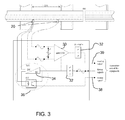
- the voltmeter functions as a high gain amplifier, which is able to multiply an input voltage by around 60000, as shown in Figure 3 .
- the voltmeter comprises the differential amplifier 30, and frequency filters 32.
- the voltmeter 22 powers the sensors 20 through isolation circuits 34 and also has a monitoring arrangement 36 for detecting sensor failure to provide an alarm signal 38.
- a 160 ⁇ V voltage is presented across the voltmeter sensors 20 (which based on the example above is the maximum that could arise), an output of a 1V signal is provided at the output terminal 39 with noises suppressed.
- the voltmeter is for example designed to enable measurement of the voltage produced by a current as low as 100mA current flowing in the 300mm length of rail. Therefore, this enables accurate analysis of the monitored IBJ electrical performance for a range of possible leakage currents.
- the voltmeter is connected to the rail and therefore particular safety precautions are required. Because the voltmeter is in constant contact with the rail, linear fuses and a surge arrester can be included, to protect against sparks and overloads.
- the sensors need to be well clipped to the rail, and one possible arrangement is shown in Figure 4 .
- the sensor is mounted in an insulated stem 40 within a housing 42 that clips to the rail.
- the sensor is spring biased (spring 43) against the rail surface, and movement of the sensor is detected by a switch 44 to provide the alarm signal 38 as explained above.
- the alarm signal can be provided over a twisted cable 46, and the sensor signal is preferably provided over an armoured cable 48.
- the cable linking the IBJ voltmeter to the rest of the equipment is a copper trackside cable 50 as shown in Figure 5 .
- the sensors are supplied by isolated power supplies as explained above.
- the voltmeter is provided in a shielded box 42, itself included in an IP68 polyester enclosure.
- the system can be formed in a modular manner, for example with up to eight IBJ voltmeters monitored by an electronic analyser 52. If the voltmeters are situated beside the track, the electronic analyser 52 is located in a railway cupboard 54. The analyser can be small (e.g. 200 x 300 x 150mm). The system is fed by the main supply (110V/240V 50Hz), and it communicates with the other railway equipment 56 via a RS485 protocol.
- the main supply 110V/240V 50Hz
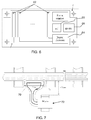
- the electronic analyser 52 preferably has a steel case. As shown in Figure 6 , it contains PCBs 62 (hereinafter insulated barrier PCB) for each voltmeter, and the shared electronics analyser PCB.
- the analyser comprises digital electronics components 64 and a microcontroller 65, which provides power signals to the sensors. The calculation results are sent to the other railway devices via a RS485 link 66.
- the microcontroller can implement fast Fourier transforms and can be configured to generate alarms when the monitored IBJ is failing.
- the insulated barrier PCBs provide an electrical isolation of more than 1kV between an IBJ voltmeter and the rest of the device. Each voltmeter has provided an associated IBJ Insulated Barrier PCB. Thus, if only four IBJ voltmeters are used by the device, just four insulated barrier PCBs will be necessary. This enables an adaptable modular system.
- the system preferably provides a real time analysis of the amplitude, and the real and imaginary components and flow direction of the IBJ current.
- An interrupt signal can be generated when the current is too high and considered as abnormal. This abnormal level is determined and set by the microcontroller.
- the system preferably includes noise filtering to improve the resolution of the output signal and therefore produce a more accurate alarm threshold.
- Figure 7 shows one possible noise filtering arrangement.
- a cable loop antenna 70 is placed between the sleepers and connected to the IBJ monitoring system 72.
- the noise measured on this antenna is fed into the filtering and amplification system (of Figure 3 ) and is used as a feedback parameter to remove the equivalent noise measured in the rail.
- any track circuit current measured in the rail will not be found in the signal from the antenna loop.
- Utilising Common Mode Rejection techniques it is possible to filter any noise that is measured equally in both the rail and the antenna.
- the antenna can be mounted in any desired orientation, although a vertical orientation has proven to provide the best feedback operation.
- the output from the monitoring system then has a low level or no unwanted noise resulting in an increased level of resolution in the output signal and the potential for a more sensitive alarm threshold.
- the invention provides a new measurement tool for monitoring a track circuit fitted with insulated block joints. It provides the first solution giving observation, in real time, of the state of an insulated block joint. This is achieved without connection between the monitored track circuit and its neighbouring track circuit. Therefore, it guarantees a total safety of the track circuit.
- Interrupt routines can be used by the microcontroller, to enable the system to catch and to analyse all changes in IBJ conditions. These conditions depend for example on the weather (humidity, temperature), and the interrupt level can be constantly tuned taking this into account.
- the system can be designed to have a long life, need minimal maintenance, consume little energy, and have excellent temperature resilience (for example working from -20°C to 70°C).
- the silicon IC components enable small dimensions, and therefore the electronic analyser can be mounted in a small railway cupboard.
- the system can be powered by the mains (110V or 240V) or the low power consumption also enables power to be supplied by means of a battery with solar charging.
- the system is flexible and in one example can be configured to supervise up to eight IBJs; giving a cost effective solution.
- the monitoring arrangement can be provided as an add-on to an existing track circuit, or it can be installed with a new track circuit. It does not require any additional current to be provided to the rail, as it simply uses the existing track circuit current. Thus, it does not interfere in any way with normal track circuit functions.
Landscapes
- Engineering & Computer Science (AREA)
- Automation & Control Theory (AREA)
- Mechanical Engineering (AREA)
- Physics & Mathematics (AREA)
- General Physics & Mathematics (AREA)
- Train Traffic Observation, Control, And Security (AREA)
- Arrangements For Transmission Of Measured Signals (AREA)
Applications Claiming Priority (1)
| Application Number | Priority Date | Filing Date | Title |
|---|---|---|---|
| GB0901881A GB2467559A (en) | 2009-02-06 | 2009-02-06 | Insulated rail joint monitoring apparatus and method |
Publications (2)
| Publication Number | Publication Date |
|---|---|
| EP2216229A2 true EP2216229A2 (fr) | 2010-08-11 |
| EP2216229A3 EP2216229A3 (fr) | 2012-04-04 |
Family
ID=40469619
Family Applications (1)
| Application Number | Title | Priority Date | Filing Date |
|---|---|---|---|
| EP10152007A Withdrawn EP2216229A3 (fr) | 2009-02-06 | 2010-01-28 | Appareil et procédé de surveillance pour joints de rail isolés |
Country Status (2)
| Country | Link |
|---|---|
| EP (1) | EP2216229A3 (fr) |
| GB (1) | GB2467559A (fr) |
Cited By (5)
| Publication number | Priority date | Publication date | Assignee | Title |
|---|---|---|---|---|
| RU2453460C1 (ru) * | 2010-12-24 | 2012-06-20 | Николай Николаевич Балуев | Устройство для приема сигнала из рельсовой цепи |
| WO2013131571A1 (fr) * | 2012-03-08 | 2013-09-12 | Siemens Aktiengesellschaft | Détection de l'état occupé ou libre d'un tronçon de voie ferrée par évaluation d'état de la séparation électrique par rapport au tronçon de voie ferrée voisin |
| EP2749470A1 (fr) * | 2012-12-28 | 2014-07-02 | Société Nationale des Chemins de Fer Français - SNCF | Procédé et dispositif de contrôle de l'isolation électrique entre deux portions de voies ferrées, et voie ferrée équipée d'un tel dispositif |
| WO2015011529A1 (fr) | 2013-07-26 | 2015-01-29 | Alstom Transport Technologies | Dispositif de vérification d'intégrité de joint mécanique de circuit de voie |
| ITUB20153936A1 (it) * | 2015-09-28 | 2017-03-28 | Carlo Gavazzi Automation S P A | Dispositivo di rilevamento dei punti di dispersione di corrente nei circuiti di binario |
Family Cites Families (9)
| Publication number | Priority date | Publication date | Assignee | Title |
|---|---|---|---|---|
| US1765715A (en) * | 1923-04-16 | 1930-06-24 | Byers Dwight | Means for testing leakage through insulated joints |
| US2614151A (en) * | 1948-07-30 | 1952-10-14 | Westinghouse Air Brake Co | Means for determining the resistance of insulated joints |
| US4886226A (en) * | 1988-06-23 | 1989-12-12 | General Signal Corporation | Broken rail and/or broken rail joint bar detection |
| US5045787A (en) * | 1989-12-27 | 1991-09-03 | General Signal Corporation | Apparatus and method for measuring insulated track joint resistances |
| FR2758301B1 (fr) * | 1997-01-10 | 1999-04-09 | Cogifer | Systeme de surveillance d'au moins un canton d'un reseau ferroviaire |
| GB9716827D0 (en) * | 1997-08-09 | 1997-10-15 | G T Railway Maintenance Limite | Insulated joint tester |
| GB9808496D0 (en) * | 1998-04-22 | 1998-06-17 | Gec Alsthom Ltd | Resistance-monitoring arrangement |
| AT406857B (de) * | 1998-05-20 | 2000-10-25 | Vae Ag | Einrichtung zum überwachen von gleisfrei-meldeanlagen |
| DE29917828U1 (de) * | 1999-10-09 | 2001-03-01 | Hanning & Kahl GmbH & Co., 33813 Oerlinghausen | Vorrichtung zur Befestigung eines Radlenkers an einer Weiche |
-
2009
- 2009-02-06 GB GB0901881A patent/GB2467559A/en not_active Withdrawn
-
2010
- 2010-01-28 EP EP10152007A patent/EP2216229A3/fr not_active Withdrawn
Non-Patent Citations (1)
| Title |
|---|
| None |
Cited By (6)
| Publication number | Priority date | Publication date | Assignee | Title |
|---|---|---|---|---|
| RU2453460C1 (ru) * | 2010-12-24 | 2012-06-20 | Николай Николаевич Балуев | Устройство для приема сигнала из рельсовой цепи |
| WO2013131571A1 (fr) * | 2012-03-08 | 2013-09-12 | Siemens Aktiengesellschaft | Détection de l'état occupé ou libre d'un tronçon de voie ferrée par évaluation d'état de la séparation électrique par rapport au tronçon de voie ferrée voisin |
| EP2749470A1 (fr) * | 2012-12-28 | 2014-07-02 | Société Nationale des Chemins de Fer Français - SNCF | Procédé et dispositif de contrôle de l'isolation électrique entre deux portions de voies ferrées, et voie ferrée équipée d'un tel dispositif |
| FR3000457A1 (fr) * | 2012-12-28 | 2014-07-04 | Sncf | Procede et dispositif de controle de l'isolation electrique entre deux portions de voies ferrees, et voie ferree equipee d'un tel dispositif |
| WO2015011529A1 (fr) | 2013-07-26 | 2015-01-29 | Alstom Transport Technologies | Dispositif de vérification d'intégrité de joint mécanique de circuit de voie |
| ITUB20153936A1 (it) * | 2015-09-28 | 2017-03-28 | Carlo Gavazzi Automation S P A | Dispositivo di rilevamento dei punti di dispersione di corrente nei circuiti di binario |
Also Published As
| Publication number | Publication date |
|---|---|
| GB2467559A (en) | 2010-08-11 |
| GB0901881D0 (en) | 2009-03-11 |
| EP2216229A3 (fr) | 2012-04-04 |
Similar Documents
| Publication | Publication Date | Title |
|---|---|---|
| US6371417B1 (en) | Railway wheel counter and block control systems | |
| US6779761B2 (en) | Broken rail detection | |
| KR101360951B1 (ko) | 레일 손상 검지 장치 및 그 방법 | |
| EP2216229A2 (fr) | Appareil et procédé de surveillance pour joints de rail isolés | |
| CN105051996A (zh) | 用于保护电气网络的设备 | |
| KR101044681B1 (ko) | 레일 파손 검출 방법 및 장치 | |
| EP2344898A2 (fr) | Coupleur résistant aux décharges partielles pour application à des barres de bus d'alternateur haute tension | |
| CN104837670B (zh) | 用于识别作为直流铁路系统中的轨道电势的交流电压的测量装置和方法以及测量装置的应用 | |
| BR102017026315A2 (pt) | Método para detecção de quebra de trilho ferroviário, sistema de detecção de quebra de trilho ferroviário e dispositivo detector de quebra de trilho ferroviário | |
| US9669733B2 (en) | Self-insulated modular power supply line | |
| RU2406624C1 (ru) | Система электроснабжения электрифицированных железных дорог переменного тока | |
| RU2603331C2 (ru) | Способ определения места короткого замыкания и повреждения контактной сети постоянного и переменного тока и устройство для его осуществления | |
| RU33077U1 (ru) | Датчик проследования рельсового подвижного состава | |
| KR20200039514A (ko) | 궤도회로 불평형 모니터링 장치 | |
| PL324261A1 (en) | Self-signalling loop-closing connection for a protected rail section | |
| RU2710840C1 (ru) | Способ и мобильное устройство контроля целостности рельсовых нитей | |
| US20090309610A1 (en) | Electrical safety devices | |
| CN104176093A (zh) | 一种用于计轴系统的继电器安全驱动及检测方法 | |
| RU103523U1 (ru) | Устройство контроля исправности электрической изоляции между рельсами и железобетонной шпалой | |
| SU1717849A1 (ru) | Электрическа установка дл подземной контактной электровозной откатки | |
| JP2022169851A (ja) | 電気融雪器センサ及び監視システム | |
| CN204903631U (zh) | 一种柜外验电装置 | |
| RU93748U1 (ru) | Устройство контроля схода подвижного состава | |
| SU1150115A1 (ru) | Устройство дл контрол состо ни т говой сети | |
| Arai et al. | Evaluation of Level Crossing Lightning Protection Measures |
Legal Events
| Date | Code | Title | Description |
|---|---|---|---|
| PUAI | Public reference made under article 153(3) epc to a published international application that has entered the european phase |
Free format text: ORIGINAL CODE: 0009012 |
|
| AK | Designated contracting states |
Kind code of ref document: A2 Designated state(s): AT BE BG CH CY CZ DE DK EE ES FI FR GB GR HR HU IE IS IT LI LT LU LV MC MK MT NL NO PL PT RO SE SI SK SM TR |
|
| AX | Request for extension of the european patent |
Extension state: AL BA RS |
|
| PUAL | Search report despatched |
Free format text: ORIGINAL CODE: 0009013 |
|
| AK | Designated contracting states |
Kind code of ref document: A3 Designated state(s): AT BE BG CH CY CZ DE DK EE ES FI FR GB GR HR HU IE IS IT LI LT LU LV MC MK MT NL NO PL PT RO SE SI SK SM TR |
|
| AX | Request for extension of the european patent |
Extension state: AL BA RS |
|
| RIC1 | Information provided on ipc code assigned before grant |
Ipc: G01R 31/02 20060101ALI20120229BHEP Ipc: B61L 1/18 20060101ALI20120229BHEP Ipc: B61L 1/20 20060101AFI20120229BHEP |
|
| STAA | Information on the status of an ep patent application or granted ep patent |
Free format text: STATUS: THE APPLICATION IS DEEMED TO BE WITHDRAWN |
|
| 18D | Application deemed to be withdrawn |
Effective date: 20120801 |