EP2216541A1 - Soupape d'injection de carburant pour dispositif d'injection de carburant à accumulateur - Google Patents
Soupape d'injection de carburant pour dispositif d'injection de carburant à accumulateur Download PDFInfo
- Publication number
- EP2216541A1 EP2216541A1 EP08856459A EP08856459A EP2216541A1 EP 2216541 A1 EP2216541 A1 EP 2216541A1 EP 08856459 A EP08856459 A EP 08856459A EP 08856459 A EP08856459 A EP 08856459A EP 2216541 A1 EP2216541 A1 EP 2216541A1
- Authority
- EP
- European Patent Office
- Prior art keywords
- nozzle
- fuel injection
- fuel
- opening
- lift
- Prior art date
- Legal status (The legal status is an assumption and is not a legal conclusion. Google has not performed a legal analysis and makes no representation as to the accuracy of the status listed.)
- Withdrawn
Links
Images


Classifications
-
- F—MECHANICAL ENGINEERING; LIGHTING; HEATING; WEAPONS; BLASTING
- F02—COMBUSTION ENGINES; HOT-GAS OR COMBUSTION-PRODUCT ENGINE PLANTS
- F02M—SUPPLYING COMBUSTION ENGINES IN GENERAL WITH COMBUSTIBLE MIXTURES OR CONSTITUENTS THEREOF
- F02M61/00—Fuel-injectors not provided for in groups F02M39/00 - F02M57/00 or F02M67/00
- F02M61/16—Details not provided for in, or of interest apart from, the apparatus of groups F02M61/02 - F02M61/14
-
- F—MECHANICAL ENGINEERING; LIGHTING; HEATING; WEAPONS; BLASTING
- F02—COMBUSTION ENGINES; HOT-GAS OR COMBUSTION-PRODUCT ENGINE PLANTS
- F02M—SUPPLYING COMBUSTION ENGINES IN GENERAL WITH COMBUSTIBLE MIXTURES OR CONSTITUENTS THEREOF
- F02M2200/00—Details of fuel-injection apparatus, not otherwise provided for
- F02M2200/28—Details of throttles in fuel-injection apparatus
-
- F—MECHANICAL ENGINEERING; LIGHTING; HEATING; WEAPONS; BLASTING
- F02—COMBUSTION ENGINES; HOT-GAS OR COMBUSTION-PRODUCT ENGINE PLANTS
- F02M—SUPPLYING COMBUSTION ENGINES IN GENERAL WITH COMBUSTIBLE MIXTURES OR CONSTITUENTS THEREOF
- F02M47/00—Fuel-injection apparatus operated cyclically with fuel-injection valves actuated by fluid pressure
- F02M47/02—Fuel-injection apparatus operated cyclically with fuel-injection valves actuated by fluid pressure of accumulator-injector type, i.e. having fuel pressure of accumulator tending to open, and fuel pressure in other chamber tending to close, injection valves and having means for periodically releasing that closing pressure
- F02M47/027—Electrically actuated valves draining the chamber to release the closing pressure
Definitions
- the present invention relates to a fuel injection valve and a means for eradicating the surge pressure occurrence or propagation in the fuel injection valve of the accumulator injection system (a common-rail injection system), the fuel injection valve injecting the high pressure fuel supplied from a pressurized fuel accumulator, into an engine combustion chamber, through at least one nozzle hole provided in a nozzle of the valve.
- Fig. 3 shows an outline cross-section as to an example of a fuel injection valve of the accumulator injection system (a common-rail injection system).
- the fuel injection valve 100 comprises: a nozzle 1 that is provided with at least one nozzle hole 4 which are placed at the tip part of the nozzle, thereby fuel is injected through the nozzle hole, and a nozzle needle 2 is fitted into the inner cylindrical space of the nozzle 1 so that the nozzle needle 2 slides in the inner cylindrical space with reciprocating movements; a spacer 6; and, a (fuel injection valve) body 7 to which the nozzle 1 and the spacer 6 are tightly attached by a nozzle holder 17, for example, by the screw mechanism of the nozzle holder.
- the nozzle needle 2 is annexed to a needle spring shoe 8a above the nozzle needle 2 and a push rod 8b that is placed above the a needle spring shoe 8a and fitted into the inner cylindrical space of the fuel injection valve body 7 so that the push rod slides in the inner cylindrical space with reciprocating movements.
- the numeral 9 denotes a needle spring that presses the nozzle needle 2 against the valve seat 5a, namely, the needle spring determines the opening pressure of the nozzle needle valve.
- the numeral 11 denotes a fuel inlet piece in which a fuel inlet passage 12 is formed.
- the fuel inlet passage 12 communicates with a fuel passage 14a and a fuel passage 14b that are formed in the fuel injection valve body 7, thereby the fuel passage 14a communicates with a fuel sump 5 that is a space filled with fuel in the nozzle and surrounds the nozzle needle 2.
- the fuel passage 14b communicates with a backward space of the push rod 8b, namely, a space above the push rod 8b via an orifice 13; thus, with a fuel pressure in the backward space, the push rod 8b, the needle spring shoe 8a and the nozzle needle can be thrust downward toward the valve seat (in the case where the needle valve is closed).
- the numeral 14 denotes a solenoid that actuates a pilot needle valve locating at an upper side of the fuel injection valve; when the pilot needle valve is closed, the pressure in the space above the push rod holds so that the nozzle needle 2 is closed; on the other hand, when the pilot needle valve is opened, the pressure in the space above the push rod is released so that the nozzle needle 2 is opened.
- the fuel injection timing is controlled.
- the numeral 24 denotes a fuel drain passage.
- patent reference 1 JP2000-27734 discloses an example as to the fuel injection valve of the accumulator injection system, whereby the steep rising of the fuel injection rate is restrained so as to reduce the nitrogen oxide generation (NOx generation).
- Figs. 4, 4(A), / 4(B) and 4(C) explain the state of the fuel injection as to the fuel injection valve 100 of the accumulator injection system (i.e. a common-rail injection system) as depicted in Fig.3 .
- a high pressure injection rate (see Fig. 4(C) ) is maintained until the moment before the injection shot is completed in order to inject the highly pressurized fuel that is accumulated in the common-rail; under such a condition, the nozzle needle 2 is going to sit on the valve seat 5a so that the fuel injection valve closes.
- Fig. 4(A) depicts the change as to the lift of the nozzle needle 2.
- a high surge pressure S is caused in the high-pressure fuel lines (such as a high-pressure line 19, the fuel passage 14a and the fuel passage 14b) as depicted in Fig. 4(B) .
- the fuel injection valve is provided with a major nozzle needle (a master nozzle needle) and a subsidiary nozzle needle (a slave nozzle needle) that are operated independently of each other; thereby, at the commencement of the injection shot, the fuel injection rate is controlled so that the injection rate is restrained only by use of the lift of the major nozzle needle; after the fuel injection rate reaches a certain amount (a prescribed or predetermined amount), both the nozzle needles are operated together; thus, the change of the fuel injection rate in the beginning of a fuel injection shot is slow in raising, and the nitrogen oxide generation (NOx generation) is restrained.
- a major nozzle needle a master nozzle needle
- a subsidiary nozzle needle a slave nozzle needle
- the movement limitation mechanism such as a stopper is provided for both the nozzle needles that are operated independently of each other; thus, the configuration of the fuel injection valve becomes complicated; further, since such a pair of the intricate nozzle needles is incorporated near the tip part of the nozzle the tip part which is exposed to high temperature, both the nozzle needles are prone to be operated under an unstable repeatability condition or under a mutually uncoupled movement condition.
- the present disclosure aims at providing a fuel injection valve of the accumulator injection system, whereby the surge pressure caused by the change of the fuel injection rate when the nozzle needle begins to be seated on or be lifted up from the valve seat is reduced or lessened; the deterioration as to the fuel injection performance and the strength of the injection valve components the deterioration which is caused by the surge pressures is prevented.
- the present invention discloses a fuel injection valve of the accumulator injection system, the fuel injection valve comprising:
- the fuel injection valve is provided with a throat, which opening is smaller than the opening (lift opening) corresponding to the lift of the nozzle needle while the lift opening is not larger than a certain level, is provided at an upstream side of the valve seat, so that the highly pressurized fuel flow is squeezed;
- the injection valve as an embodiment of the invention is provided with the throat apart from the lift opening, said throat being provided at each upper edge of more than two vertical grooves that are engraved on the outer periphery surface of the nozzle needle and form more than two passages of the highly pressurized fuel, the throat being provided on the upstream side of the lift opening; or the injection valve as an embodiment of the invention is provided with the throat apart from the lift opening, said throat which is provided between an outer conical surface around the needle the outer conical surface which is formed at an upstream side of the valve seat for the needle, and an inner conical surface in the nozzle the inner conical surface which corresponds to the outer conical surface, so that the opening of the provided throat is smaller than the lift opening while the lift
- the slope as to the fuel injection rate becomes gentler during the period where the lift opening located between the nozzle needle 2 and the valve seat 5a is smaller than the certain level, the surge pressures can be restrained; as a result, a fuel injection device is obtained whereby the deterioration of the fuel injection performance and the strength of the injection valve components the deterioration which is caused by the surge pressure can be prevented. Further, since the slope of the fuel injection rate becomes gentler during the period where the lift opening located between the nozzle needle 2 and the valve seat 5a reaches the certain level, from the commencement of the needle valve opening, the nitrogen oxide generation (NOx generation) can be reduced, and the exhaust gas emission properties can be improved.
- NOx generation nitrogen oxide generation
- the throat apart from the lift opening is provided at each upper edge of more than two vertical grooves that are engraved on the outer periphery surface of the nozzle needle and form more than two passages of the highly pressurized fuel, the throat being provided at the each upper edge of the grooves, on the upstream side of the lift opening;
- the throat apart from the lift opening is provided between an outer conical surface around the needle the outer conical surface which is formed at an upstream side of the valve seat for the nozzle needle, and an inner conical surface in the nozzle the inner conical surface which corresponds to the outer conical surface, so that the opening of the provided throat is smaller than the lift opening while the lift opening is not larger than a certain level.
- the configuration of the first embodiment can be realized by the structure only of the nozzle needle 2, while the configuration of the second embodiment can be realized by the combination of the structures of the nozzle needle 2 and the nozzle 1. Accordingly, in comparison with the structure disclosed by the patent reference 1, the present invention provides a fuel injection valve of a simple structure; further, the structure near the tip part of the nozzle can be simple the tip part which is exposed to high temperature. Thus, the fuel injection can be operated under a stable repeatability condition.
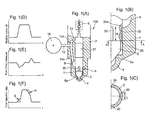
- Figs. 1(A) to 1(F) depicts an outline configuration as to a fuel injection valve of the accumulator injection system, according to the first embodiment of the present invention.
- an fuel injection valve 100 is provided with:
- the numeral 18 denotes a pressurized fuel accumulator to which a fuel inlet passage 12 is communicated.
- the fuel inlet passage 12 communicates with a fuel passage 14a and a fuel passage 14b. Further, the fuel passage 14a communicates with a fuel sump 5 that is a space filled with fuel in the nozzle and surrounds the nozzle needle 2.
- the fuel passage 14b communicates with a backward space of the push rod 8b, namely, a space above a control rod 31 via the orifice 13; thus, with a fuel pressure, the control rod 31, the needle spring shoe 8a and the nozzle needle can be thrust downward toward the valve seat.
- the fuel injection valve is provided with a solenoid for operating the fuel injection valve, namely, the nozzle needle 2; the nozzle needle valve 2 is operated so as to close or open, through the movements of the pilot needle valve that is operated by the solenoid.
- the nozzle needle 2 is provided with a step 25 at the lower guide part of the nozzle needle 2; upward the step 25, more than two vertical grooves 30 of the width C and the length W are formed on the surface of the lower guide part of the nozzle needle 2 along the flow direction of the highly pressurized fuel downward the nozzle needle.
- a step 25 at the lower guide part of the nozzle needle 2; upward the step 25, more than two vertical grooves 30 of the width C and the length W are formed on the surface of the lower guide part of the nozzle needle 2 along the flow direction of the highly pressurized fuel downward the nozzle needle.
- a flow throat at the upper edge 30a of each groove 30 is formed only while the needle valve 2 begins to open till the nozzle needle is lifted up so that the throat is no longer a throttle that squeezes the fuel flow downward the groove to the valve seat 5a, namely, until the opening between the nozzle needle 2 and the valve seat 5a reaches the certain level.
- the highly pressurized fuel flow downward through the opening is restrained during the period where the lift of the nozzle needle is smaller than a certain level.
- the slope as to the fuel injection rate becomes gentler thanks to the throttle effect, in comparison with a case where the grooves 30 and the throats thereof are dispensed with, as the pointers A and B in Fig. 1(F) indicates.
- the slope as to the fuel injection rate becomes gentler during the period where the opening between the nozzle needle 2 and the valve seat 5a is smaller than the certain level; therefore, as shown in Fig. 1(E) , the surge pressures are restrained (compare Fig. 1(E) and Fig. 4(B) ); as a result, a fuel injection device is obtained whereby the deterioration as to the fuel injection performance and the strength of the injection valve components the deterioration which is caused by the surge pressure can be prevented.
- the slope as to the fuel injection rate becomes gentler during the period where the opening between the nozzle needle 2 and the valve seat 5a reaches the certain level, from the commencement of the needle valve opening, the nitrogen oxide generation (NOx generation) can be reduced, and the exhaust gas emission properties can be improved.
- the injection flow rate is determined only by the opening (the lift opening) over the seat 5a (i.e. the lift of the nozzle needle); namely, the injection flow rate is not influenced by the upper throat that no longer forms a throttle; thus, the highly pressurized fuel is injected without the influence of the throttle.
- a throat 35 is provided between the nozzle needle 2 and the nozzle 1.
- the throat 35 is formed between:
- the opening of the throat 35 is slightly opened when the nozzle needle 2 sits on the valve seat 5a; and, the slightly opened condition as to the throat 35 continues for a (prescribed or predetermined) period while the lift opening is not larger than a certain level; thus, the highly pressurized fuel toward the valve seat 5a is squeezed.
- the slope as to the fuel injection rate becomes gentler during the period where the lift opening between the nozzle needle 2 and the valve seat 5a is smaller than the certain level the surge pressures can be restrained, as shown in Fig. 2(E) , as a result, a fuel injection device is obtained whereby the deterioration as to the fuel injection performance and the strength of the injection valve components the deterioration which is caused by the surge pressure can be prevented. Further, since the slope as to the fuel injection rate becomes gentler during the period where the lift opening between the nozzle needle 2 and the valve seat 5a reaches the certain level, from the commencement of the needle valve opening, the nitrogen oxide generation (NOx generation) can be reduced, and the exhaust gas emission properties can be improved.
- NOx generation nitrogen oxide generation
- the throat 35 no longer forms a throttle; then, the injection flow rate is determined only by the opening over the seat 5a (i.e. the lift or lift opening of the nozzle needle) ; namely, the injection flow rate is not influenced by the throat 35 that no longer forms a throttle; thus, the highly pressurized fuel is injected without the influence of the throat 35.
- the throat apart from the lift opening is provided at each upper edge of more than two vertical grooves 30 that are engraved on the outer periphery surface of the nozzle needle and form more than two passages of the highly pressurized fuel, the throat being provided at the each upper edge 30a of the grooves, on the upstream side of the lift opening;
- the throat 35 apart from the lift opening is provided between an outer conical surface 2s around the needle the outer conical surface which is formed at an upstream side of the valve seat 5a for the nozzle needle 2, and an inner conical surface 1s in the nozzle the inner conical surface which corresponds to the outer conical surface, so that the opening as to the provided throat is smaller than the lift opening while the lift opening is not larger than a certain level.
- the configuration of the first embodiment can be realized by the structure only of the nozzle needle 2, while the configuration of the second embodiment can be realized by the combination of the structures of the nozzle needle 2 and the nozzle 1. Accordingly, in comparison with the structure disclosed by the patent reference 1, the present invention provides a fuel injection valve of a simple structure; further, the structure near the tip part of the nozzle can be simple the tip part which is exposed to high temperature. Thus, the fuel injection can be operated under a stable repeatability condition.
- the present provides a fuel injection valve of the accumulator injection system, whereby the surge pressure caused by the change of the fuel injection rate when the nozzle needle begin to be seated on or be lifted up from the valve seat is reduced or lessened; the deterioration as to the fuel injection performance and the strength of the injection valve components the deterioration which is caused by the surge pressures is prevented.
Landscapes
- Engineering & Computer Science (AREA)
- Chemical & Material Sciences (AREA)
- Combustion & Propulsion (AREA)
- Mechanical Engineering (AREA)
- General Engineering & Computer Science (AREA)
- Fuel-Injection Apparatus (AREA)
Applications Claiming Priority (2)
| Application Number | Priority Date | Filing Date | Title |
|---|---|---|---|
| JP2007315270A JP2009138614A (ja) | 2007-12-05 | 2007-12-05 | 蓄圧式燃料噴射装置の燃料噴射弁 |
| PCT/JP2008/067867 WO2009072345A1 (fr) | 2007-12-05 | 2008-09-25 | Soupape d'injection de carburant pour dispositif d'injection de carburant à accumulateur |
Publications (2)
| Publication Number | Publication Date |
|---|---|
| EP2216541A1 true EP2216541A1 (fr) | 2010-08-11 |
| EP2216541A4 EP2216541A4 (fr) | 2011-03-23 |
Family
ID=40717526
Family Applications (1)
| Application Number | Title | Priority Date | Filing Date |
|---|---|---|---|
| EP08856459A Withdrawn EP2216541A4 (fr) | 2007-12-05 | 2008-09-25 | Soupape d'injection de carburant pour dispositif d'injection de carburant à accumulateur |
Country Status (4)
| Country | Link |
|---|---|
| US (1) | US20100200678A1 (fr) |
| EP (1) | EP2216541A4 (fr) |
| JP (1) | JP2009138614A (fr) |
| WO (1) | WO2009072345A1 (fr) |
Families Citing this family (1)
| Publication number | Priority date | Publication date | Assignee | Title |
|---|---|---|---|---|
| DE102009028089A1 (de) * | 2009-07-29 | 2011-02-10 | Robert Bosch Gmbh | Kraftstoffeinspritzventil mit erhöhter Kleinmengenfähigkeit |
Family Cites Families (23)
| Publication number | Priority date | Publication date | Assignee | Title |
|---|---|---|---|---|
| US379456A (en) * | 1888-03-13 | Geoege w | ||
| JPS58189366U (ja) * | 1982-06-09 | 1983-12-16 | 日産自動車株式会社 | ホール型燃料噴射ノズル |
| JPS60132065A (ja) * | 1983-12-20 | 1985-07-13 | Nissan Motor Co Ltd | 燃料噴射ノズル |
| JPS6123462U (ja) * | 1984-07-17 | 1986-02-12 | 株式会社ボッシュオートモーティブ システム | 燃料噴射弁 |
| GB9008403D0 (en) * | 1990-04-12 | 1990-06-13 | Lucas Ind Plc | Fuel injection nozzle |
| US5533482A (en) * | 1994-05-23 | 1996-07-09 | Nissan Motor Co., Ltd. | Fuel injection nozzle |
| JP3791456B2 (ja) * | 1994-05-23 | 2006-06-28 | 日産自動車株式会社 | 内燃機関の燃料噴射弁 |
| JPH08105365A (ja) * | 1994-10-05 | 1996-04-23 | Hino Motors Ltd | ディーゼル機関の噴射ノズル |
| GB9425652D0 (en) * | 1994-12-20 | 1995-02-22 | Lucas Ind Plc | Fuel injection nozzle |
| DE19623713B4 (de) * | 1996-06-14 | 2008-06-19 | Robert Bosch Gmbh | Einspritzventil, insbesondere zum direkten Einspritzen von Kraftstoff in einen Brennraum eines Verbrennungsmotors |
| DE19633260A1 (de) * | 1996-08-17 | 1998-02-19 | Bosch Gmbh Robert | Einspritzventil, insbesondere zum direkten Einspritzen von Kraftstoff in einen Brennraum eines Verbrennungsmotors |
| DE19744739A1 (de) * | 1997-10-10 | 1999-04-15 | Bosch Gmbh Robert | Brennstoffeinspritzventil |
| DE19755057A1 (de) * | 1997-12-11 | 1999-06-17 | Bosch Gmbh Robert | Kraftstoffeinspritzdüse für selbstzündende Brennkraftmaschinen |
| JPH11351101A (ja) * | 1998-06-09 | 1999-12-21 | Denso Corp | 内燃機関用燃料噴射弁 |
| JP2000027734A (ja) | 1998-07-14 | 2000-01-25 | Mitsubishi Motors Corp | ディーゼルエンジンの燃料噴射弁 |
| DE19942370A1 (de) * | 1999-09-04 | 2001-03-22 | Bosch Gmbh Robert | Einspritzdüse für Brennkraftmaschinen mit einer Ringnut in der Düsennadel |
| US6499467B1 (en) * | 2000-03-31 | 2002-12-31 | Cummins Inc. | Closed nozzle fuel injector with improved controllabilty |
| DE10055651A1 (de) * | 2000-11-10 | 2002-05-23 | Bosch Gmbh Robert | Druckgesteuerter Injektor mit optimierten Einspritzverlauf über den Hubweg |
| DE10062959A1 (de) * | 2000-12-16 | 2002-06-20 | Bosch Gmbh Robert | Kraftstoffeinspritzventil für Brennkraftmaschinen |
| US20020155832A1 (en) * | 2001-04-18 | 2002-10-24 | Stucky Michael J. | Wireless telemetry system |
| DE10208222A1 (de) * | 2002-02-26 | 2003-10-30 | Bosch Gmbh Robert | Brennstoffeinspritzventil |
| DE10249144A1 (de) * | 2002-10-22 | 2004-05-06 | Robert Bosch Gmbh | Kraftstoffeinspritzventil für Brennkraftmaschinen |
| DE102004025729A1 (de) * | 2004-05-26 | 2005-12-15 | Robert Bosch Gmbh | Kraftstoffeinspritzventil für eine Brennkraftmaschine |
-
2007
- 2007-12-05 JP JP2007315270A patent/JP2009138614A/ja active Pending
-
2008
- 2008-09-25 EP EP08856459A patent/EP2216541A4/fr not_active Withdrawn
- 2008-09-25 US US12/673,376 patent/US20100200678A1/en not_active Abandoned
- 2008-09-25 WO PCT/JP2008/067867 patent/WO2009072345A1/fr not_active Ceased
Also Published As
| Publication number | Publication date |
|---|---|
| JP2009138614A (ja) | 2009-06-25 |
| US20100200678A1 (en) | 2010-08-12 |
| WO2009072345A1 (fr) | 2009-06-11 |
| EP2216541A4 (fr) | 2011-03-23 |
Similar Documents
| Publication | Publication Date | Title |
|---|---|---|
| EP0967383B1 (fr) | Injecteur de combustible | |
| US6793161B1 (en) | Needle lift damper device of injector for fuel injection and needle lift damping method | |
| RU2170846C2 (ru) | Устройство впрыскивания топлива для двигателей внутреннего сгорания | |
| US5522545A (en) | Hydraulically actuated fuel injector | |
| US6145492A (en) | Control valve for a fuel injection valve | |
| US20130112767A1 (en) | Fuel Injector With Needle Control System That Includes F, A, Z and E Orifices | |
| JP2012193748A (ja) | 内燃機関用の燃料噴射弁の弁ニードルにおける絞り | |
| CN101910605B (zh) | 降低了操作中随时间的变化的发动机和控制阀组件 | |
| US20030127614A1 (en) | Electromagnetic valve for controlling an injection valve of an internal combustion engine | |
| JP5236018B2 (ja) | 改良バルブ制御装置を持つ燃料インジェクタ | |
| EP2134954B1 (fr) | Dispositif de commande de l'injection du carburant dans un moteur à combustion interne et procédé de commande de l'injection du carburant dans un moteur à combustion interne | |
| JP2014125971A (ja) | 燃料噴射弁 | |
| WO2000055490A1 (fr) | Injecteur de carburant | |
| EP0779430A1 (fr) | Injecteur | |
| US7568634B2 (en) | Injection nozzle | |
| US20100200678A1 (en) | Fuel injection valve of accumulator injection system | |
| KR20020038691A (ko) | 내연기관용 연료 분사 장치 | |
| JP5237054B2 (ja) | 蓄圧式燃料噴射装置の制御弁構造 | |
| EP3004625B1 (fr) | Soupape de commande pour injecteur de carburant | |
| GB2424451A (en) | Fuel injection valve with concentric inner and outer valve needles | |
| EP2829718B1 (fr) | Agencement d'injecteur | |
| EP2177744B1 (fr) | Soupape d'injection de carburant pour dispositif d'injection de carburant du type accumulation de pression | |
| JPH0447415Y2 (fr) | ||
| JP2010515855A (ja) | カップラを備えた燃料インジェクタ | |
| EP1717435B1 (fr) | Buse d'injection |
Legal Events
| Date | Code | Title | Description |
|---|---|---|---|
| PUAI | Public reference made under article 153(3) epc to a published international application that has entered the european phase |
Free format text: ORIGINAL CODE: 0009012 |
|
| 17P | Request for examination filed |
Effective date: 20100215 |
|
| AK | Designated contracting states |
Kind code of ref document: A1 Designated state(s): AT BE BG CH CY CZ DE DK EE ES FI FR GB GR HR HU IE IS IT LI LT LU LV MC MT NL NO PL PT RO SE SI SK TR |
|
| AX | Request for extension of the european patent |
Extension state: AL BA MK RS |
|
| DAX | Request for extension of the european patent (deleted) | ||
| A4 | Supplementary search report drawn up and despatched |
Effective date: 20110217 |
|
| 17Q | First examination report despatched |
Effective date: 20120705 |
|
| STAA | Information on the status of an ep patent application or granted ep patent |
Free format text: STATUS: THE APPLICATION IS DEEMED TO BE WITHDRAWN |
|
| 18D | Application deemed to be withdrawn |
Effective date: 20121116 |