EP2216652A1 - Appareil d'inspection par chromatographie et procédé pour déterminer la dégradation d'un spécimen de chromatographie - Google Patents
Appareil d'inspection par chromatographie et procédé pour déterminer la dégradation d'un spécimen de chromatographie Download PDFInfo
- Publication number
- EP2216652A1 EP2216652A1 EP08844241A EP08844241A EP2216652A1 EP 2216652 A1 EP2216652 A1 EP 2216652A1 EP 08844241 A EP08844241 A EP 08844241A EP 08844241 A EP08844241 A EP 08844241A EP 2216652 A1 EP2216652 A1 EP 2216652A1
- Authority
- EP
- European Patent Office
- Prior art keywords
- chromatography
- specimen
- luminance
- liquid sample
- degraded
- Prior art date
- Legal status (The legal status is an assumption and is not a legal conclusion. Google has not performed a legal analysis and makes no representation as to the accuracy of the status listed.)
- Withdrawn
Links
Images



Classifications
-
- G—PHYSICS
- G01—MEASURING; TESTING
- G01N—INVESTIGATING OR ANALYSING MATERIALS BY DETERMINING THEIR CHEMICAL OR PHYSICAL PROPERTIES
- G01N21/00—Investigating or analysing materials by the use of optical means, i.e. using sub-millimetre waves, infrared, visible or ultraviolet light
- G01N21/84—Systems specially adapted for particular applications
- G01N21/8483—Investigating reagent band
-
- G—PHYSICS
- G01—MEASURING; TESTING
- G01N—INVESTIGATING OR ANALYSING MATERIALS BY DETERMINING THEIR CHEMICAL OR PHYSICAL PROPERTIES
- G01N30/00—Investigating or analysing materials by separation into components using adsorption, absorption or similar phenomena or using ion-exchange, e.g. chromatography or field flow fractionation
- G01N30/90—Plate chromatography, e.g. thin layer or paper chromatography
- G01N30/95—Detectors specially adapted therefor; Signal analysis
-
- G—PHYSICS
- G01—MEASURING; TESTING
- G01N—INVESTIGATING OR ANALYSING MATERIALS BY DETERMINING THEIR CHEMICAL OR PHYSICAL PROPERTIES
- G01N33/00—Investigating or analysing materials by specific methods not covered by groups G01N1/00 - G01N31/00
- G01N33/48—Biological material, e.g. blood, urine; Haemocytometers
- G01N33/50—Chemical analysis of biological material, e.g. blood, urine; Testing involving biospecific ligand binding methods; Immunological testing
- G01N33/53—Immunoassay; Biospecific binding assay; Materials therefor
- G01N33/543—Immunoassay; Biospecific binding assay; Materials therefor with an insoluble carrier for immobilising immunochemicals
- G01N33/54366—Apparatus specially adapted for solid-phase testing
- G01N33/54386—Analytical elements
- G01N33/54387—Immunochromatographic test strips
- G01N33/54388—Immunochromatographic test strips based on lateral flow
-
- G—PHYSICS
- G01—MEASURING; TESTING
- G01N—INVESTIGATING OR ANALYSING MATERIALS BY DETERMINING THEIR CHEMICAL OR PHYSICAL PROPERTIES
- G01N2201/00—Features of devices classified in G01N21/00
- G01N2201/12—Circuits of general importance; Signal processing
- G01N2201/124—Sensitivity
- G01N2201/1242—Validating, e.g. range invalidation, suspending operation
Definitions
- the present invention relates to a chromatography inspection apparatus for conducting an inspection by optically detecting a signal to measure a component concentration in a liquid sample, and a method for judging degradation of a chromatography specimen.
- a dry-type biosensor such as a chromatography specimen using immune response does not require any adjustments of a reagent and enables an analysis of a target analyte in a liquid sample such as blood and urine only with a simple operation such as dropping of the liquid sample to be inspected.
- a liquid sample such as blood and urine
- a simple operation such as dropping of the liquid sample to be inspected.
- many dry-type biosensors have been put into practical use as typical POCT.
- FIG. 5 is a perspective view showing the configuration of the chromatography specimen according to the prior art.
- reference numeral 1 denotes a specimen for chromatography (hereinafter called a specimen) and reference numeral 2 denotes a support that supports a chromatography material and is made of a plastic and the like.
- Reference numeral 3 denotes a developing layer that develops a liquid sample and is made of nitrocellulose and the like.
- Reference numeral 4 denotes a sample adding part for adding or applying the liquid sample.
- Reference numeral 5 denotes a labeling reagent retaining part for retaining a labeling reagent that is disposed so as to be melted by the development of a sample on the developing layer.
- Reference numeral 6 denotes a reagent fixing part for fixing a reagent such as specific protein on a region of the developing layer 3.
- Reference numeral 7 denotes a water absorbing part for absorbing the liquid sample in the end.
- Reference numeral 8 denotes a transparent liquid-impermeable sheet material that is made up of plastic tape and the like. The liquid-impermeable sheet material 8 tightly covers a part of the specimen 1 except for end regions upstream and downstream of the specimen 1.
- the labeling reagent retaining part 5, the reagent fixing part 6, and the water absorbing part 7 are each configured as a part of the developing layer 3.
- a liquid sample added to the sample adding part 4 starts developing the developing layer 3 and reaches the region of the labeling reagent retaining part 5.
- a labeling reagent retained in the region of the labeling reagent retaining part 5 is melted by the development of the liquid sample and develops downstream of the developing layer 3 along with the liquid sample.
- the reagent fixing part 6 is provided on the developing layer 3.
- the liquid sample contains a target analyte
- specific protein fixed in the reagent fixing part 6 causes a combination reaction with a composite of the target analyte and the labeling reagent and a color reaction occurs in the region of the reagent fixing part 6, whereas when the liquid sample does not contain the target analyte, a combination reaction or a color reaction does not occur.
- the liquid sample develops to the water absorbing part 7 in the extreme downstream region of the developing layer 3, so that the operation of the specimen 1 is completed.
- the liquid-impermeable sheet material 8 made up of transparent plastic tape and the like, thereby preventing water evaporation.
- the measurement region ranges from the labeling reagent retaining part 5 located upstream of a surface of the developing layer 3 to the reagent fixing part 6 located downstream of the labeling reagent retaining part 5.
- the liquid-impermeable sheet material 8 makes it possible to evenly develop the liquid sample over the measurement region and keep constant the concentrations of the liquid sample and the labeling reagent that pass through the measurement region for a certain period of time, so that a chromatography inspection can be conducted with accuracy.
- the concentration of the target analyte in the liquid sample can be detected by a method of reading reflection absorbance by using a reflectance spectrophotometer. Further, the concentration of the target analyte can be detected by a method of capturing a coloration result of the specimen 1 as an image by an image pickup device such as a camera and performing arithmetic processing.
- an adhesive for bonding the liquid-impermeable sheet material 8 to the developing layer 3 permeates the upper portion of the developing layer 3 and causes degradation that is reduced hydrophilicity.
- the chromatography inspection apparatus may disadvantageously conduct an erroneous measurement.
- the present invention has as its object the provision of a chromatography inspection apparatus that enables an accurate inspection by detecting degradation of a specimen during a chromatography inspection.
- a chromatography inspection apparatus of the present invention conducts an inspection by developing a liquid sample in the developing layer of a chromatography specimen on which a liquid-impermeable sheet material is bonded, melting a labeling reagent retained in a labeling reagent retaining part, and coloring a reagent fixing part by the labeling reagent, the chromatography inspection apparatus including: an image pickup device for imaging the chromatography specimen in a state in which the liquid sample has developed; and a measuring section for judging whether the chromatography specimen has been degraded or not based on an imaging result, wherein when the measuring section judges that the chromatography specimen has been degraded, a warning is issued.
- the measuring section determines, based on the imaging result, a difference in luminance between the labeling reagent retaining part and a region located downstream of the labeling reagent retaining part in the developing direction, and the measuring section judges that the chromatography specimen has been degraded when the difference is larger than a preset reference value.
- the measuring section determines, based on the imaging result, a difference in luminance between a region where the liquid sample has developed and a region located in the developing direction downstream of the end of the region where the liquid sample has developed, and the measuring section judges that the chromatography specimen has been degraded when the difference is smaller than the preset reference value.
- the measuring section determines, based on the imaging result, the luminance variation of the region where the liquid sample has developed, and the measuring section judges that the chromatography specimen has been degraded when the luminance variation is larger than the preset reference value.
- the measuring section determines, based on the imaging result, a difference in luminance between a region where the liquid-impermeable sheet material is bonded and a region located in the developing direction downstream of the end of the region where the liquid-impermeable sheet material is bonded, and the measuring section judges that the chromatography specimen has been degraded when the difference is larger than the preset reference value.
- a method of judging degradation of a chromatography specimen according to the present invention in which degradation of the chromatography specimen is detected concurrently with a chromatography inspection conducted by developing a liquid sample in the developing layer of the chromatography specimen on which a liquid-impermeable sheet material is bonded, melting a labeling reagent retained in a labeling reagent retaining part, and coloring a reagent fixing part by the labeling reagent, the method including: imaging the chromatography specimen in a state in which the liquid sample has developed; and judging whether the chromatography specimen has been degraded or not based on an imaging result, wherein when it is judged that the chromatography specimen has been degraded during the inspection, an inspection operation is stopped.
- the judging step includes: determining a difference in luminance between the labeling reagent retaining part and a region located downstream of the labeling reagent retaining part in the developing direction after the liquid sample has developed; and comparing the determined luminance difference with a preset reference value and judging that the chromatography specimen has been degraded when the luminance difference is larger than the reference value.
- the judging step includes: determining, after the liquid sample has developed, a difference in luminance between a region where the liquid sample has developed and a region located in the developing direction downstream of the end of the region where the liquid sample has developed; and comparing the determined luminance difference with the preset reference value and judging that the chromatography specimen has been degraded when the luminance difference is smaller than the reference value.
- the judging step includes: determining, after the liquid sample has developed, the luminance variation of the region where the liquid sample has developed; and comparing the luminance variation with the preset reference value and judging that the chromatography specimen has been degraded when the luminance variation is larger than the reference value.
- the judging step includes: determining, after the liquid sample has developed, a difference in luminance between a region where the liquid-impermeable sheet material is bonded and a region located in the developing direction downstream of the end of the region where the liquid-impermeable sheet material is bonded; and comparing the determined luminance difference with the preset reference value and judging that the chromatography specimen has been degraded when the luminance difference is larger than the reference value.
- FIG. 1 is a schematic drawing showing the configurations of a specimen and the chromatography inspection apparatus for measuring a coloration result of the specimen.
- a specimen 1 has the same configuration as in FIG. 5 of the prior art and thus the explanation thereof is omitted.
- the chromatography inspection apparatus of FIG. 1 includes a light-emitting device 9, a diaphragm 10, a condenser lens 11, an image pickup device 12, and a measuring section 20.
- the light-emitting device 9 is a lamp, a light-emitting diode, a semiconductor laser, or the like and has the function of illuminating the specimen 1.
- the diaphragm 10 restricts scattered light from the specimen 1.
- the condenser lens 11 condenses scattered light on the image pickup device 12 and forms, on a surface of the image pickup device 12, an image of a surface of the specimen 1. After that, the image pickup device 12 converts the light into an electric signal.
- the electric signal from the image pickup device 12 is converted into a digital signal by a signal conversion unit 13 and image processing is performed by an image processing unit 14 such that the noise components of each pixel of the image pickup device 12 are removed and a measurement region is extracted.
- the degree of coloration of a reagent fixing part 6 is calculated as absorbance by an absorbance calculation unit 15.
- the absorbance is used.in a concentration judgment unit 16 to calculate the concentration of a target analyte in a liquid sample according to a concentration conversion formula having been inputted to the apparatus.
- the concentration is displayed by an output unit 17.
- the light-emitting device 9 is a light-emitting diode having a wavelength of 610 nm.
- the wavelength is selected under the conditions that a sufficient difference in absorbance between gold colloid (labeling reagent) and blood (liquid sample) is obtained.
- the labeling reagent is gold colloid and the liquid sample is blood.
- the image pickup device 12 is a CCD (Charge Coupled Device) image sensor or a CMOS (Complementary Metal Oxide Semiconductor) image sensor.
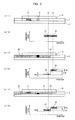
- FIG. 2 is an explanatory drawing showing a method of detecting degradation in the chromatography inspection apparatus according to the first embodiment.
- Part (a-1), part (b-1), and part (c-1) in FIG. 2 are sectional views showing the specimen 1 of FIG. 1 along chain line A-A' of FIG. 1 .
- Part (a-2), part (b-2), and part (c-2) in FIG. 2 schematically show the levels of the luminance signals so as to clarify a difference between point B and point C of FIG. 2 , the luminance signals being obtained by the image pickup device at point B and point C.
- the horizontal axis indicates a position along chain line A-A' of the specimen 1 and the vertical axis indicates the level of the luminance signal.
- Point B and point C are located at the front and rear of the downstream end of a labeling reagent retaining part 5.
- Point B is located on the labeling reagent retaining part 5.
- Part (a-1) of FIG. 2 shows a state in which blood (liquid sample) is not added.
- the liquid-impermeable sheet material 8 is in contact with the top surface of a developing layer 3, and the labeling reagent retaining part 5 and the reagent fixing part 6 are provided on the developing layer 3.
- a comparison between the levels of a luminance signal 21 at point B and a luminance signal 22 at point C proves that the level of the luminance signal 21 is extremely lower. This is because illumination light is absorbed by gold colloid (labeling reagent).
- Part (b-1) of FIG. 2 shows a state in which blood (liquid sample) 23 has been added to the normal specimen 1 and then a development end (the position of the front end of the permeating liquid sample) 24 of the blood (liquid sample) 23 has passed through the labeling reagent retaining part 5 and is present in a range where the liquid-impermeable sheet material 8 is bonded.
- the gold colloid (labeling reagent) retained in the region of the labeling reagent retaining part 5 is completely melted by the developed blood (liquid sample) 23.
- part (b-2) of FIG. 2 a comparison between the levels of a luminance signal 25 at point B and a luminance signal 26 at point C immediately after melting proves that the signals are substantially at the same level.
- Part (c-1) of FIG. 2 shows a state in which the blood (liquid sample) 23 has been added to the degraded specimen 1 and then the development end 24 of the blood (liquid sample) 23 has passed through the labeling reagent retaining part 5 and is present in a range where the liquid-impermeable sheet material 8 is bonded.
- Reference numeral 27 denotes a region where an adhesive for bonding the liquid-impermeable sheet material 8 to the developing layer 3 permeates the upper portion of the developing layer 3 and hydrophilicity decreases. Because of the decrease in hydrophilicity, the blood (liquid sample) 23 added to the specimen 1 develops so as to avoid the hydrophilicity decreasing region 27. At this point, as shown in part (c-2) of FIG.
- a comparison between the levels of a luminance signal 28 at point B and a luminance signal 29 at point C proves that the level of the luminance signal 28 is lower.
- the blood (liquid sample) 23 does not develop in the hydrophilicity decreasing region 27 and thus does not melt the gold colloid (labeling reagent) in an overlapping portion of the labeling reagent retaining part 5 and the hydrophilicity decreasing region 27 and more illumination light is absorbed in the overlapping portion.
- a difference in luminance level between point B and point C in part (c-2) of FIG. 2 is larger than that of part (b-2), so that degradation of the specimen 1 can be judged by detecting the difference.
- the chromatography inspection apparatus judges degradation of the specimen by the following operations: first, the image pickup device 12 obtains an image of the specimen 1 and converts the image into an electric signal, the signal, conversion unit 13 converts the electric signal into a digital signal, and then the image processing unit 14 performs image processing for removing the noise components of each pixel of the image pickup device 12 and extracting the measurement region. After point B and point C are extracted by a signal measurement unit 18, luminance signal levels are detected at both of the points. In this case, the luminance signal level at point C is continuously monitored at time intervals having been inputted to the apparatus (about one second is desirable in practical use).
- a degradation judgment unit 19 determines a level difference between point B and point C (C-B) and compares the level difference with another reference value having been inputted to the apparatus. When the level difference is larger than the reference value, it is judged that the specimen 1 has been degraded.
- the time interval and the reference value that have been inputted to the apparatus may be stored in memory provided in the chromatography inspection apparatus or may be stored in memory provided in the degradation judgment unit 19.
- the chromatography inspection apparatus issues a warning to a user through an error indication on the output unit 17 and stops the inspection operation performed on the specimen.
- luminances are measured on the labeling reagent retaining part and a portion downstream of the labeling reagent retaining part in a state in which the liquid sample has developed in the portion, and a difference in luminance level is detected.
- the difference in luminance level is larger than the preset reference value, it is judged that the chromatography specimen has been degraded so as to decrease in hydrophilicity and the inspection can be stopped. It is therefore possible to automatically detect degradation of the specimen during the chromatography inspection, enabling an accurate inspection.
- FIGS. 1 and 3 the operations of a chromatography inspection apparatus according to a second embodiment of the present invention will be described below.
- two methods of judging degradation of a specimen will be also described.
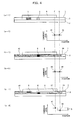
- FIG. 3 is an explanatory drawing showing the method of detecting degradation in the chromatography inspection apparatus according to the second embodiment.
- states of the development of blood (liquid sample) 33 to a specimen 1 and examples of luminance signals are vertically illustrated in the same drawing.
- Part (a-1), part (b-1), and part (c-1) in FIG. 3 are sectional views showing the specimen 1 of FIG. 1 along chain line A-A' of FIG. 1 .
- Part (a-2), part (b-2), and part (c-2) in FIG. 3 schematically show the levels of the luminance signals so as to clarify a difference between point D and point E of FIG. 3 , the luminance signals being obtained by an image pickup device at point D and point E.
- the horizontal axis indicates a position along chain line A-A' of the specimen 1 and the vertical axis indicates the level of the luminance signal.
- point D and point E are set in a range where a liquid-impermeable sheet material 8 is provided and are located in a region downstream of a reagent fixing part 6. Degradation is detected when the liquid sample develops to a point between point D and point E.
- Part (a-1) of FIG. 3 shows a state in which the blood (liquid sample) is not added.
- the liquid-impermeable sheet material 8 is in contact with the top surface of a developing layer 3, and a labeling reagent retaining part 5 and the reagent fixing part 6 are provided on the developing layer 3.
- a comparison between the levels of a luminance signal 31 at point D and a luminance signal 32 at point E proves that the signals are substantially at the same level. This is because luminances in the same surface state of the developing layer 3 are compared with each other.
- Part (a-2) of FIG. 3 also shows subtle changes (hereinafter called a "luminance change” and an amount of luminance change will be called a luminance variation) of the luminance signals relative to an observation position. These changes are caused by an image of unevenness on the fiber of the developing layer 3. In this image, a convex portion looks bright by illumination light and a recessed portion looks dark behind the convex portion. Although similar luminance changes are present in FIG. 2 illustrated in the first embodiment, the luminance changes are omitted in FIG. 2 for simplicity.
- Part (b-1) of FIG. 3 shows a state in which the blood (liquid sample) 33 has been added to the normal specimen 1 and then the blood (liquid sample) 33 has passed through the reagent fixing part 6 and developed to the intermediate position of point D and point E.
- a comparison between the levels of a luminance signal 35 at point D and a luminance signal 36 at point E proves that the level of the luminance signal 35 is lower. This is because the blood (liquid sample) 33 containing melted gold colloid (labeling reagent) is present at point D and illumination light is absorbed at point D.
- Nd a luminance variation around the luminance signal 35
- Ne a luminance variation around the luminance signal 36
- Part (c-1) of FIG. 3 shows a state in which the blood (liquid sample) 33 has been added to the degraded specimen 1 and then the blood (liquid sample) 33 has passed through the reagent fixing part 6 and developed to the intermediate position of point D and point E.
- Reference numeral 27 denotes a region where an adhesive for bonding the liquid-impermeable sheet material 8 to the developing layer 3 permeates the upper portion of the developing layer 3 and hydrophilicity decreases. Because of the decrease in hydrophilicity, the blood (liquid sample) 33 added to the specimen 1 develops so as to avoid the hydrophilicity decreasing region 27. At this point, as shown in part (c-2) of FIG.
- a comparison between the levels of a luminance signal 37 at point D and a luminance signal 38 at point E proves that the level of the luminance signal 37 is lower.
- the blood (liquid sample) 33 containing melted gold colloid (labeling reagent) is present under the hydrophilicity decreasing region 27 and thus illumination light from a light-emitting device 9 is partially absorbed by the blood (liquid sample) 33.
- the blood (liquid sample) 33 is not present in the hydrophilicity decreasing region 27 at point D of part (c-2) in FIG. 3 and the absorbance of illumination light decreases, accordingly.
- degradation of the specimen 1 can be judged by detecting the difference.
- Nd and Ne are substantially equal to each other. This is because around either of the positions of the luminance signal 37 and the luminance signal 38, a surface of the specimen 1 has the dry developing layer 3 (the hydrophilicity decreasing region 27) and light and shade caused by unevenness of fiber are clearly imaged.
- Nd of part (c-2) in FIG. 3 is larger than that of part (b-2), so that degradation of the specimen 1 can be judged by detecting the difference.
- the chromatography inspection apparatus judges degradation of the specimen 1 by the following operations:
- an image pickup device 12 obtains an image of the specimen 1 and converts the image into an electric signal, a signal conversion unit 13 converts the electric signal into a digital signal, and then an image processing unit 14 performs image processing for removing the noise components of each pixel of the image pickup device 12 and extracting a measurement region.
- luminance signal levels are detected at both of the points.
- the luminance signal level at point D is continuously monitored at time intervals having been inputted to the apparatus (about one second is desirable in practical use). When the luminance signal level falls below a level having been inputted to the apparatus, it is judged that the blood (liquid sample) 33 has developed over point D.
- a degradation judgment unit 19 determines a level difference between point D and point E (E-D) and compares the level difference with another reference value having been inputted to the apparatus. When the level difference is smaller than the reference value, it is judged that the specimen 1 has been degraded.
- the time interval and the reference value that have been inputted to the apparatus may be stored in memory provided in the chromatography inspection apparatus or may be stored in memory provided in the degradation judgment unit 19.
- the chromatography inspection apparatus issues a warning to a user through an error indication on an output unit 17 and stops the inspection operation performed on the inspected specimen 1.
- the signal measurement unit 18 detects a luminance variation Nd at point D and the degradation judgment unit 19 compares Nd with another reference value having been inputted to the apparatus. When Nd is larger than the reference value, it is judged that the specimen 1 has been degraded. When it is judged that the specimen 1 has been degraded, the chromatography inspection apparatus issues a warning to a user through an error indication on the output unit 17 and stops the inspection operation performed on the specimen 1.
- luminances are measured in a region where the liquid sample has developed and a portion downstream of the end of the region where the liquid sample has developed, in a state in which the liquid sample develop has developed. Further, a difference in luminance level is detected. Hence, when a difference in luminance level is smaller than a preset reference value, it is judged that the chromatography specimen has been degraded so as to decrease in hydrophilicity and the inspection can be stopped. It is therefore possible to automatically detect degradation of the specimen during the chromatography inspection, enabling an accurate inspection.
- FIG. 4 is an explanatory drawing showing a method of detecting degradation in the chromatography inspection apparatus according to the third embodiment.
- states of the development of blood (liquid sample) to a specimen 1 and examples of luminance signals are vertically illustrated in the same drawing.
- Part (a-1), part (b-1), and part (c-1) in FIG. 4 are sectional views showing the specimen 1 of FIG. 1 along chain line A-A' of FIG. 1 .
- Part (a-2), part (b-2), and part (c-2) in FIG. 4 schematically show the levels of the luminance signals of FIG. 4 so as to clarify a difference between point F and point G, the luminance signals being obtained by an image pickup device at point F and point G.
- the horizontal axis indicates a position along chain line A-A' of the specimen 1 and the vertical axis indicates the level of the luminance signal.
- points F and G are located at the front and rear of the development downstream end of a liquid-impermeable sheet material 8.
- Point F is located on the liquid-impermeable sheet material 8 and point G is located on a water absorbing part 7 to which the liquid-impermeable sheet material 8 is not bonded.
- Part (a-1) of FIG. 4 shows a state in which the blood (liquid sample) is not added.
- the liquid-impermeable sheet material 8 is in contact with the top surface of a developing layer 3, and a labeling reagent retaining part 5 and a reagent fixing part 6 are provided on the developing layer 3.
- a comparison between the levels of a luminance signal 41 at point F and a luminance signal 42 at point G proves that the signals are substantially at the same level. This is because luminances in the same surface state of the developing layer 3 are compared with each other.
- FIG. 3 shows a state of a luminance change, a luminance change is omitted in FIG. 4 for simplicity.
- Part (b-1) of FIG. 4 shows a state in which blood (liquid sample) 43 has been added to the normal specimen 1 and then a development end 44 of the blood (liquid sample) 43 has passed through the development downstream end of the liquid-impermeable sheet material 8 and developed to the water absorbing part 7.
- a comparison between the levels of a luminance signal 45 at point F and a luminance signal 46 at point G proves that the signals are substantially at the same level.
- the impermeable sheet material 8 is provided at point F but does not affect the luminance signal because of its transparency, so that luminances in the same surface state of the developing layer 3 are compared with each other.
- Part (c-1) of FIG. 4 shows a state in which the blood (liquid sample) 43 has been added to the degraded specimen 1 and then the development end 44 of the blood (liquid sample) 43 has passed through the development downstream end of the liquid-impermeable sheet material 8 and developed to the water absorbing part 7.
- Reference numeral 27 denotes a region where an adhesive for bonding the liquid-impermeable sheet material 8 to the developing layer 3 permeates the upper portion of the developing layer 3 and hydrophilicity decreases. Because of the decrease in hydrophilicity, the blood (liquid sample) 43 added to the specimen 1 develops so as to avoid the hydrophilicity decreasing region 27. At this point, as shown in part (c-2) of FIG.
- a comparison between the levels of a luminance signal 47 at point F and a luminance signal 48 at point G proves that the level of the luminance signal 48 is lower. This is because the impermeable sheet material 8 and the hydrophilicity decreasing region 27 are not present at point G and thus the blood (liquid sample) 43 permeates to a surface of the developing layer 3 and absorbs illumination light.
- a level difference between point F and point G is larger in part (c-2) of FIG. 4 , so that degradation of the specimen 1 can be judged by detecting the difference.
- the chromatography inspection apparatus judges degradation of the specimen 1 by the following operations: first, an image pickup device 12 obtains an image of the specimen 1 and converts the image into an electric signal, a signal conversion unit 13 converts the electric signal into a digital signal, and then an image processing unit 14 performs image processing for removing the noise components of each pixel of the image pickup device 12 and extracting a measurement region. Further, a signal measurement unit 18 detects luminance signal levels at point F and point G. In this case, the luminance signal level at point G is continuously monitored at time intervals having been inputted to the apparatus (about one second is desirable in practical use).
- a degradation judgment unit 19 determines a level difference between point F and point G (F-G) and compares the level difference with another reference value having been inputted to the apparatus. When the level difference is larger than the reference value, it is judged that the specimen 1 has been degraded.
- the time interval and the reference value that have been inputted to the apparatus may be stored in memory provided in the chromatography inspection apparatus or may be stored in memory provided in the degradation judgment unit 19.
- the chromatography inspection apparatus issues a warning to a user through an error indication on an output unit 17 and stops the inspection operation performed on the specimen 1.
- luminances are measured at the front and rear of the development downstream end of the liquid-impermeable sheet material 8 in a state in which the liquid sample has developed, and a difference in luminance level is detected.
- a difference in luminance level is larger than the preset reference value, it is judged that the chromatography specimen has been degraded so as to decrease in hydrophilicity and the inspection can be stopped. It is therefore possible to automatically detect degradation of the specimen during the chromatography inspection, enabling an accurate inspection.
- the third embodiment described that the labeling reagent retaining part 5 is disposed on the developing layer 3. Instead of this configuration, the same effect can be obtained by developing the developing layer 3 in a state in which gold colloid (labeling reagent) has been mixed in blood (liquid sample).
- the specimen sample is a blood sample.
- Other samples such as urine, saliva, and body fluid can be used without any trouble.
- the first to third embodiments described the apparatus for detecting a reduction in the hydrophilicity of the developing layer.
- the hydrophilicity is reduced by the permeating adhesive of the liquid-impermeable sheet material.
- the apparatus is also applicable to a similar hydrophilicity decreasing region generated by another member or reagent.
- the first to third embodiments described the use of the signals obtained by imaging the specimen 1 with the image pickup device.
- the present invention is similarly applicable to the case where illumination light is condensed and is emitted to the specimen 1 and a change of scattered light amount is used as a signal when the illumination light and the specimen 1 are relatively moved.
- a measuring method of the present invention is applicable as a measuring method using a biosensor for quickly analyzing a biological sample with high reliability and measuring accuracy.
Landscapes
- Health & Medical Sciences (AREA)
- Life Sciences & Earth Sciences (AREA)
- Immunology (AREA)
- Chemical & Material Sciences (AREA)
- Engineering & Computer Science (AREA)
- Molecular Biology (AREA)
- Physics & Mathematics (AREA)
- Pathology (AREA)
- General Physics & Mathematics (AREA)
- General Health & Medical Sciences (AREA)
- Biochemistry (AREA)
- Analytical Chemistry (AREA)
- Urology & Nephrology (AREA)
- Hematology (AREA)
- Biomedical Technology (AREA)
- Medicinal Chemistry (AREA)
- Food Science & Technology (AREA)
- Microbiology (AREA)
- Cell Biology (AREA)
- Biotechnology (AREA)
- Investigating Or Analysing Materials By The Use Of Chemical Reactions (AREA)
- Investigating Or Analysing Materials By Optical Means (AREA)
- Investigating Or Analysing Biological Materials (AREA)
Applications Claiming Priority (2)
| Application Number | Priority Date | Filing Date | Title |
|---|---|---|---|
| JP2007285616A JP4850165B2 (ja) | 2007-11-02 | 2007-11-02 | クロマトグラフィー検査装置およびクロマトグラフィー試験片の劣化判定方法 |
| PCT/JP2008/002888 WO2009057252A1 (fr) | 2007-11-02 | 2008-10-14 | Appareil d'inspection par chromatographie et procédé pour déterminer la dégradation d'un spécimen de chromatographie |
Publications (2)
| Publication Number | Publication Date |
|---|---|
| EP2216652A1 true EP2216652A1 (fr) | 2010-08-11 |
| EP2216652A4 EP2216652A4 (fr) | 2010-11-03 |
Family
ID=40590659
Family Applications (1)
| Application Number | Title | Priority Date | Filing Date |
|---|---|---|---|
| EP08844241A Withdrawn EP2216652A4 (fr) | 2007-11-02 | 2008-10-14 | Appareil d'inspection par chromatographie et procédé pour déterminer la dégradation d'un spécimen de chromatographie |
Country Status (5)
| Country | Link |
|---|---|
| US (1) | US8447084B2 (fr) |
| EP (1) | EP2216652A4 (fr) |
| JP (1) | JP4850165B2 (fr) |
| CN (1) | CN101802613B (fr) |
| WO (1) | WO2009057252A1 (fr) |
Families Citing this family (11)
| Publication number | Priority date | Publication date | Assignee | Title |
|---|---|---|---|---|
| JP5205354B2 (ja) * | 2009-09-30 | 2013-06-05 | 富士フイルム株式会社 | クロマトグラフ測定装置 |
| EA201000176A1 (ru) * | 2010-01-11 | 2010-08-30 | Общество С Ограниченной Ответственностью Научно-Производственное Объединение "Биотест" (Ооо Нпо "Биотест") | Тест-система "кардиотест" для иммунохроматографического определения сердечного белка, связывающего жирные кислоты, и тропонина i в образце цельной крови для экспресс-диагностики инфаркта миокарда |
| CA2850693C (fr) * | 2011-11-14 | 2016-04-19 | F. Hoffmann-La Roche Ag | Instrument d'analyse pour le depistage d'au moins un analyte dans un echantillon |
| JP6491868B2 (ja) * | 2014-12-15 | 2019-03-27 | テルモ株式会社 | 尿試験情報取得装置及び尿試験情報管理システム |
| EP3581931B1 (fr) * | 2017-02-08 | 2020-12-23 | Fujifilm Corporation | Dispositif d'essai immunologique |
| CN110268267B (zh) * | 2017-02-14 | 2022-11-11 | 富士胶片株式会社 | 免疫检查装置 |
| TWI867847B (zh) * | 2018-02-15 | 2024-12-21 | 美商雷傑納榮製藥公司 | 用於在程序層析法中失效模式偵測之系統及方法 |
| EP4317987A4 (fr) | 2021-03-24 | 2024-10-09 | FUJIFILM Corporation | Dispositif de test immunochromatographique |
| WO2022203017A1 (fr) | 2021-03-24 | 2022-09-29 | 富士フイルム株式会社 | Dispositif d'essai d'immunochromatographie |
| WO2022202261A1 (fr) * | 2021-03-24 | 2022-09-29 | 富士フイルム株式会社 | Dispositif de test immunochromatographique |
| EP4498087A4 (fr) | 2022-03-22 | 2025-07-30 | Fujifilm Corp | Appareil d'inspection immunochromatographique |
Family Cites Families (10)
| Publication number | Priority date | Publication date | Assignee | Title |
|---|---|---|---|---|
| JPH055736A (ja) * | 1991-06-27 | 1993-01-14 | Omron Corp | 尿試験紙および自動尿検査装置 |
| US5585070A (en) * | 1994-04-29 | 1996-12-17 | Phoenix International Life Sciences Inc. | Method for extraction, extraction cartridge and automated extraction processing system |
| US6267722B1 (en) * | 1998-02-03 | 2001-07-31 | Adeza Biomedical Corporation | Point of care diagnostic systems |
| JP4430263B2 (ja) * | 2000-04-28 | 2010-03-10 | パナソニック株式会社 | クロマトグラフィ測定装置 |
| EP1202058B1 (fr) | 2000-04-28 | 2008-05-14 | Matsushita Electric Industrial Co., Ltd. | Instrument de mesure par chromatographie |
| JP4562854B2 (ja) * | 2000-05-08 | 2010-10-13 | パナソニック株式会社 | クロマトグラフィー測定方法 |
| JP2003004743A (ja) * | 2001-06-22 | 2003-01-08 | Matsushita Electric Ind Co Ltd | クロマトグラフィー定量測定装置 |
| WO2002025253A1 (fr) | 2000-09-25 | 2002-03-28 | Matsushita Electric Industrial Co., Ltd. | Dispositif de mesure quantitative par procede chromatographique |
| CN101258406A (zh) | 2005-07-14 | 2008-09-03 | 松下电器产业株式会社 | 分析装置及分析方法 |
| JP4799116B2 (ja) * | 2005-10-11 | 2011-10-26 | シスメックス株式会社 | 検体分析装置、検体分析方法及びコンピュータプログラム |
-
2007
- 2007-11-02 JP JP2007285616A patent/JP4850165B2/ja not_active Expired - Fee Related
-
2008
- 2008-10-14 CN CN2008801076547A patent/CN101802613B/zh not_active Expired - Fee Related
- 2008-10-14 WO PCT/JP2008/002888 patent/WO2009057252A1/fr not_active Ceased
- 2008-10-14 US US12/740,447 patent/US8447084B2/en not_active Expired - Fee Related
- 2008-10-14 EP EP08844241A patent/EP2216652A4/fr not_active Withdrawn
Also Published As
| Publication number | Publication date |
|---|---|
| JP4850165B2 (ja) | 2012-01-11 |
| US8447084B2 (en) | 2013-05-21 |
| CN101802613B (zh) | 2013-06-19 |
| WO2009057252A1 (fr) | 2009-05-07 |
| US20100260411A1 (en) | 2010-10-14 |
| JP2009115470A (ja) | 2009-05-28 |
| CN101802613A (zh) | 2010-08-11 |
| EP2216652A4 (fr) | 2010-11-03 |
Similar Documents
| Publication | Publication Date | Title |
|---|---|---|
| US8447084B2 (en) | Chromatography inspection apparatus and method for judging degradation of chromatography specimen | |
| CA2648147C (fr) | Systeme et methode pour determiner la concentration d'un analyte dans un echantillon liquide | |
| US8848988B2 (en) | Appliance and method for evaluation and assessment of a test strip | |
| Giavazzi et al. | A fast and simple label-free immunoassay based on a smartphone | |
| KR101516563B1 (ko) | 진단 스트립 삽입형 리더기 | |
| KR102603371B1 (ko) | 분석 측정을 수행하기 위한 방법 및 디바이스 | |
| CN109863386B (zh) | 使用全血折射测定的总蛋白质测量 | |
| JP5012507B2 (ja) | 分析装置、及び分析方法 | |
| US8068217B2 (en) | Apparatus for testing component concentration of a test sample | |
| KR102264336B1 (ko) | 광학식 체외진단기기와 이를 이용한 체외진단 방법 | |
| US20080100851A1 (en) | Laser array | |
| JP2009098080A (ja) | 免疫クロマトグラフィー測定装置 | |
| US20110118141A1 (en) | Disease Specific Diagnostic Aid | |
| KR100724597B1 (ko) | 간질환 진단용 면역스트립 판독기 | |
| US20070122914A1 (en) | Obtaining measurements of light transmitted through an assay test strip | |
| JP2009150856A (ja) | 試料分析方法、試料分析装置、および試験片 | |
| KR20150029290A (ko) | 진단 스트립 리더기 | |
| CN214408685U (zh) | 一种基于全反射折光法的食品分析仪 | |
| JPS59109844A (ja) | 反射光測定装置 | |
| KR101893219B1 (ko) | 체액분석 방법 및 이를 이용한 체액분석 시스템 | |
| KR20200132117A (ko) | 광학식 체외진단기기와 이를 이용한 체외진단 방법 | |
| CN101772703B (zh) | 使用生物传感器的测定方法 | |
| CN117222876A (zh) | 具有多个照明源的诊断仪器及其方法 | |
| JP7482257B2 (ja) | 検査装置、情報処理方法およびプログラム | |
| JP2022092432A (ja) | 測定精度を高めたイムノクロマトリーダ |
Legal Events
| Date | Code | Title | Description |
|---|---|---|---|
| PUAI | Public reference made under article 153(3) epc to a published international application that has entered the european phase |
Free format text: ORIGINAL CODE: 0009012 |
|
| 17P | Request for examination filed |
Effective date: 20100520 |
|
| AK | Designated contracting states |
Kind code of ref document: A1 Designated state(s): AT BE BG CH CY CZ DE DK EE ES FI FR GB GR HR HU IE IS IT LI LT LU LV MC MT NL NO PL PT RO SE SI SK TR |
|
| AX | Request for extension of the european patent |
Extension state: AL BA MK RS |
|
| RIN1 | Information on inventor provided before grant (corrected) |
Inventor name: MATSUDA, YOKO Inventor name: YAMADA, RYOSUKE Inventor name: TANIDA, TAKAHIKO Inventor name: KUROKAWA, HIDEYUKI Inventor name: TAKAHASHI, MIE Inventor name: MIYOSHI, KOJI Inventor name: AGA, MASAHIRO |
|
| A4 | Supplementary search report drawn up and despatched |
Effective date: 20101006 |
|
| RIC1 | Information provided on ipc code assigned before grant |
Ipc: G01N 21/86 20060101ALI20100930BHEP Ipc: G01N 21/88 20060101ALI20100930BHEP Ipc: G01N 30/95 20060101ALI20100930BHEP Ipc: G01N 33/53 20060101ALI20100930BHEP Ipc: G01N 21/78 20060101ALI20100930BHEP Ipc: G01N 33/543 20060101AFI20090525BHEP |
|
| DAX | Request for extension of the european patent (deleted) | ||
| RAP1 | Party data changed (applicant data changed or rights of an application transferred) |
Owner name: PANASONIC HEALTHCARE CO., LTD. |
|
| 17Q | First examination report despatched |
Effective date: 20140828 |
|
| GRAP | Despatch of communication of intention to grant a patent |
Free format text: ORIGINAL CODE: EPIDOSNIGR1 |
|
| INTG | Intention to grant announced |
Effective date: 20150504 |
|
| STAA | Information on the status of an ep patent application or granted ep patent |
Free format text: STATUS: THE APPLICATION IS DEEMED TO BE WITHDRAWN |
|
| 18D | Application deemed to be withdrawn |
Effective date: 20150915 |