EP2216709A2 - Système et procédé pour générer une interface utilisateur pour la sélection de texte et d'éléments - Google Patents
Système et procédé pour générer une interface utilisateur pour la sélection de texte et d'éléments Download PDFInfo
- Publication number
- EP2216709A2 EP2216709A2 EP10152793A EP10152793A EP2216709A2 EP 2216709 A2 EP2216709 A2 EP 2216709A2 EP 10152793 A EP10152793 A EP 10152793A EP 10152793 A EP10152793 A EP 10152793A EP 2216709 A2 EP2216709 A2 EP 2216709A2
- Authority
- EP
- European Patent Office
- Prior art keywords
- selection
- pointing device
- selection set
- movement
- item
- Prior art date
- Legal status (The legal status is an assumption and is not a legal conclusion. Google has not performed a legal analysis and makes no representation as to the accuracy of the status listed.)
- Withdrawn
Links
Images






Classifications
-
- G—PHYSICS
- G06—COMPUTING OR CALCULATING; COUNTING
- G06F—ELECTRIC DIGITAL DATA PROCESSING
- G06F3/00—Input arrangements for transferring data to be processed into a form capable of being handled by the computer; Output arrangements for transferring data from processing unit to output unit, e.g. interface arrangements
- G06F3/01—Input arrangements or combined input and output arrangements for interaction between user and computer
- G06F3/048—Interaction techniques based on graphical user interfaces [GUI]
- G06F3/0484—Interaction techniques based on graphical user interfaces [GUI] for the control of specific functions or operations, e.g. selecting or manipulating an object, an image or a displayed text element, setting a parameter value or selecting a range
- G06F3/04842—Selection of displayed objects or displayed text elements
-
- G—PHYSICS
- G06—COMPUTING OR CALCULATING; COUNTING
- G06F—ELECTRIC DIGITAL DATA PROCESSING
- G06F3/00—Input arrangements for transferring data to be processed into a form capable of being handled by the computer; Output arrangements for transferring data from processing unit to output unit, e.g. interface arrangements
- G06F3/01—Input arrangements or combined input and output arrangements for interaction between user and computer
- G06F3/02—Input arrangements using manually operated switches, e.g. using keyboards or dials
- G06F3/023—Arrangements for converting discrete items of information into a coded form, e.g. arrangements for interpreting keyboard generated codes as alphanumeric codes, operand codes or instruction codes
- G06F3/0233—Character input methods
- G06F3/0236—Character input methods using selection techniques to select from displayed items
-
- G—PHYSICS
- G06—COMPUTING OR CALCULATING; COUNTING
- G06F—ELECTRIC DIGITAL DATA PROCESSING
- G06F3/00—Input arrangements for transferring data to be processed into a form capable of being handled by the computer; Output arrangements for transferring data from processing unit to output unit, e.g. interface arrangements
- G06F3/01—Input arrangements or combined input and output arrangements for interaction between user and computer
- G06F3/048—Interaction techniques based on graphical user interfaces [GUI]
- G06F3/0481—Interaction techniques based on graphical user interfaces [GUI] based on specific properties of the displayed interaction object or a metaphor-based environment, e.g. interaction with desktop elements like windows or icons, or assisted by a cursor's changing behaviour or appearance
- G06F3/0482—Interaction with lists of selectable items, e.g. menus
-
- G—PHYSICS
- G06—COMPUTING OR CALCULATING; COUNTING
- G06F—ELECTRIC DIGITAL DATA PROCESSING
- G06F3/00—Input arrangements for transferring data to be processed into a form capable of being handled by the computer; Output arrangements for transferring data from processing unit to output unit, e.g. interface arrangements
- G06F3/01—Input arrangements or combined input and output arrangements for interaction between user and computer
- G06F3/048—Interaction techniques based on graphical user interfaces [GUI]
- G06F3/0484—Interaction techniques based on graphical user interfaces [GUI] for the control of specific functions or operations, e.g. selecting or manipulating an object, an image or a displayed text element, setting a parameter value or selecting a range
- G06F3/04845—Interaction techniques based on graphical user interfaces [GUI] for the control of specific functions or operations, e.g. selecting or manipulating an object, an image or a displayed text element, setting a parameter value or selecting a range for image manipulation, e.g. dragging, rotation, expansion or change of colour
-
- G—PHYSICS
- G06—COMPUTING OR CALCULATING; COUNTING
- G06F—ELECTRIC DIGITAL DATA PROCESSING
- G06F2203/00—Indexing scheme relating to G06F3/00 - G06F3/048
- G06F2203/048—Indexing scheme relating to G06F3/048
- G06F2203/04806—Zoom, i.e. interaction techniques or interactors for controlling the zooming operation
Definitions
- This disclosure relates to methods and systems supporting computing and data processing systems. More particularly, a system and method for generating a user interface for text and item selection is described.
- Conventional systems can display two-dimensional grid of alphanumeric characters from which a user can make selections. These conventional systems allow a user to manipulate a joystick or game controller to navigate right, left, up, and down within the grid to identify and select a desired character. Other conventional systems provide a displayed on-screen replica of a standard two-dimensional keyboard that can be navigated in a similar two-dimensional manner. However, these conventional user interfaces for text input can be slow and awkward to use.
- U.S. Patent No. 6,593,913 describes a method and system for selecting a character with a user input device comprising a plurality of buttons.
- a first plurality of characters is displayed on a display device in a pattern corresponding to a pattern of a plurality of buttons of a user input device, and a character from the first plurality of characters is selected in response to actuation of one of the plurality of buttons.
- the number of characters displayed on the display device for selection by the user input device is less than or equal to the number of buttons in the plurality of buttons. In this way, any of the characters displayed on the display device for selection by the user input device can be selected by actuation of a single one of the plurality of buttons.
- U.S. Patent No. 5,543,818 describes a method and apparatus for entering alphanumeric or other text to a computer system using an input device having a small number of keys.
- the computer system includes a processor programmed to display a character selection menu (including displayed groups of characters), to move a displayed cursor from one group to another in response to actuation of at least one cursor movement key on the input device, and to select a character within a group in response to actuation of one of at least two selection keys on the input device.
- the system reduces the maximum number of keystrokes required conventionally to select a character from a character set, and enables character selection from a larger set of displayed characters using no more keystrokes than required conventionally to select the same character from a smaller set.
- U.S. Patent No. 6,501,464 describes a graphical user interface in the form of a transparent keyboard may be positioned over an existing computer display. The user may input textual data through the keyboard by selecting keys in the transparent keyboard display. The text entry may then appear on the computer display in non-transparent or conventional format.
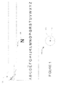
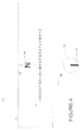
- Figures 1-5 illustrate a particular example embodiment of a user interface for computer users, electronic game players, or television (TV) users in which an item selection set is arranged in a linear orientation.
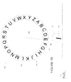
- Figures 6-10 illustrate a particular example embodiment of a user interface for computer users or electronic game players in which an item selection set is arranged in a circular orientation.
- Figure 11 illustrates a particular example embodiment of a user interface for computer users, electronic game players or TV users in which a selection set includes items representing a variety of physical or logical entities.
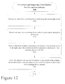
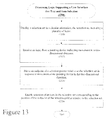
- FIGS 12 and 13 illustrate processing flow diagrams for example embodiments.
- Figure 14 is a block diagram of machine in the example form of a computer system within which instructions, for causing the machine to perform any one or more of the methodologies discussed herein, may be executed.
- Figure 1 illustrates a particular example embodiment of a user interface for computer users, electronic game players, or TV users.
- a user interface 100 is shown as may be displayed within a conventional display screen window on a computer display, electronic game system, or TV screen of a user.
- the user system may be connected or connectable to a pointing device, thumbstick device, mouse, TV remote device, a game controller device, spatial movement detection devices, such as the Wii system sold by Nintendo of America, Inc., or any other hardware or software device/system, which can signal movement in a two-dimensional space via a conventional hardware interface (hereinafter called a pointing device).
- the user system can use conventional hardware and operating system software to support the novel user interface 100 described herein.
- the user interface 100 is created using the functionality of various embodiments described herein.
- the user interface 100 in an example embodiment is comprised of a display region 102 (e.g., a window, a data entry box, etc.) in which a selection set 104 is displayed.
- the selection set 104 is comprised of a set of items, each of which may represent an individually selectable option.
- the items in selection set 104 are letters of the English language alphabet.
- the items can be a set of selectable alphanumeric characters, alphanumeric characters plus special characters, alphanumeric characters in a language other than English, mathematical symbols, geometric shapes, icons, logos, drawing primitives, objects, images, device objects, or any of a variety of other types of selectable items.
- the selection set 104 is configured in a linear pattern of evenly-spaced items extending to the borders of display region 102.
- a selection vector 106 is shown in the center of the display region 102. The selection vector 106 is used to mark a location in display region 102 at which one of the items in selection set 104 is selectable.
- selection button 112. For clarity, the selectable item overlaying (or in proximity to) selection vector 106 is reproduced as selectable item 108 as shown in Figure 1 .
- the letter, 'N' of selection set 104 is in proximity to selection vector 106. Therefore, the letter, 'N' is reproduced as selectable item 108 as shown in Figure 1 . If a user of user interface 100 shown in Figure 1 wishes to select the selectable item 108, the user can activate selection button 112.
- selection button 112 can be any form of signal generation device, such as a hardware button or softkey located anywhere on a remote device, a gesture detection device, audible command detection device, or the like.
- the selected item is saved in an item string created and saved in display area 116.
- the letter, 'N' of selection set 104 has been selected by a user by user activation of selection button 112 and the selected item (i.e., letter, 'N') has been saved in the current position of the item string in display area 116.
- the next position in the item string of display area 116 is represented by the underscore character shown in display region 116 of Figure 1 .
- a backspace button or item selection can be provided to clear a previous entry and move the string insertion point (i.e., an underscore character) backward one position.
- the example of Figure 1 also illustrates a pointing device 111, which can be deflected (or used to point) in two dimensions about a center point of a motion area 110 of the pointing device 111 as shown in Figure 1 .
- the pointing device111 is shown in Figure 1 at its neutral position (e.g., undeflected position, center position, or home position) at the center point of the pointing device motion area 110.
- the selection set 104 remains static at its current position.
- the current position is as shown with the letter, 'N' of selection set 104 in proximity to selection vector 106.
- the deflection of the pointing device 111 causes a corresponding linear motion of the selection set 104 in relation to the selection vector 106.
- the pointing device 111 can signal movement in two dimensions simultaneously or may indicate separate movements in just one direction.
- other types of pointing devices may indicate a vector movement relative to a point (e.g., the center of the motion area 110). Any of these pointing devices can be used with the various embodiments described herein.
- the user interface 100 is shown after a user has selected an item from the selection set 104 by activation of selection button 112 while the desired item is positioned in proximity to selection vector 106.
- the user has selected the letter, 'N' of selection set 104 and the selected item has been reproduced in the display region 116.
- the user has deflected the pointing device 111 to the left (the 270° position) as illustrated by the vector shown in the representation of the pointing device motion area 110 illustrated in Figure 2 .
- the selection set 104 is set in a relatively slow fluid motion to the left as shown by the arrow 113 in Figure 2 .
- the selection vector 106 remains stationary. As a result, the items in selection set 104 pass over the selection vector 106 as long as the pointing device remains deflected to the left. As each item of selection set 104 passes over the selection vector 106, the corresponding item is reproduced as selectable item 108.
- the appearance of selectable item 108 indicates to the user that the selectable item 108 can be selected by the user and copied to the display area 116, if the selection button 112 is activated at the moment the desired item is over the selection vector 106 and displayed as selectable item 108.
- the speed at which the selection set moves can be controlled by the degree of deflection of the pointing device 111 to the left or right (the the 90° position).
- the selection set 104 can move at a slow rate to the corresponding direction left or right. If the pointing device 111 is fully deflected to the left or right, the selection set 104 can move at a fast rate to the corresponding direction left or right.
- the speed of movement of the selection set for a particular level of deflection of the pointing device 111 can be preconfigured in a particular embodiment.
- a user can move the selection set 104 to the left with left deflection of the pointing device 111 to position a desired item in the selection set 104 over the selection vector 106.
- the user has moved the selection set 104 to the left with left deflection of the pointing device 111, positioned a desired item (e.g., the letter 'R') in the selection set 104 over the selection vector 106, and activated selection button 112.
- the selected item e.g., the letter 'R'
- the string insertion point i.e., an underscore character
- the user has deflected the pointing device 111 to the right (the 90° position) as illustrated by the vector shown in the representation of the pointing device motion area 110 illustrated in Figure 3 .
- the selection set 104 is set in a relatively slow fluid motion to the right as shown by the arrow 115 in Figure 3 .
- the selection vector 106 remains stationary.
- the items in selection set 104 pass over the selection vector 106 as long as the pointing device remains deflected to the right.
- the corresponding item is reproduced as selectable item 108 as described above.
- the speed at which the selection set moves to the right can be controlled by the degree of deflection of the pointing device 111 to the right.
- a user can move the selection set 104 to the right with right deflection of the pointing device 111 to position a desired item in the selection set 104 over the selection vector 106.
- the user has moved the selection set 104 to the right with right deflection of the pointing device 111, positioned a desired item (e.g., the letter 'H') in the selection set 104 over the selection vector 106, and activated selection button 112.
- the selected item e.g., the letter 'H'
- the string insertion point i.e., an underscore character
- FIG. 4 a selection set zooming feature of a particular embodiment is illustrated.
- the user has deflected the pointing device 111 in a downward (the 180° position) direction as illustrated by the vector shown in the representation of the pointing device motion area 110 illustrated in Figure 4 .
- the items in selection set 104 have been reduced in size a relatively slow fluid motion to simulate a zoom out operation in a view of the selection set 104.
- One effect of the zoom out operation as shown in the example of Figure 4 is that the spacing between the items in selection set 104 has been selectively reduced based on the amount of downward deflection of the pointing device 111 and the length of time the pointing device 111 is deflected downward. With the resulting reduced spacing between items in selection set 104, the user can more quickly navigate to a desired item with a left or right deflection of the pointing device 111. In cases where there may be many items in selection set 104, it may be desirable to use the zoom out operation provided in a particular embodiment to more quickly reach an item in selection set 104 that is located a relatively large distance away from the selection vector 106.
- a user can perform a zoom out operation to more quickly navigate to a desired item with a left or right deflection of the pointing device 111.
- the user is still given the opportunity to move the selection set 104 to the right or left with right or left deflection of the pointing device 111 to position a desired item in the selection set 104 over the selection vector 106 and make an item selection.
- the selection set zooming feature of a particular embodiment is further illustrated.
- the user has deflected the pointing device 111 in an upward (the 0° or 360° position) direction as illustrated by the vector shown in the representation of the pointing device motion area 110 illustrated in Figure 5 .
- the items in selection set 104 have been enlarged in a relatively slow fluid motion to simulate a zoom in operation in a view of the selection set 104.
- One effect of the zoom in operation as shown in the example of Figure 5 is that the spacing between the items in selection set 104 has been selectively increased based on the amount of upward deflection of the pointing device 111 and the length of time the pointing device 111 is deflected upward. With the resulting increased spacing between items in selection set 104, the user can more accurately navigate to a desired item with a left or right deflection of the pointing device 111. In cases where there may be only a few items in selection set 104 or the items are densely packed together because of display area space limitations, it may be desirable to use the zoom in operation provided in a particular embodiment to more accurately reach an item in selection set 104.
- a user can perform a zoom in operation to more accurately navigate to a desired item with a left or right deflection of the pointing device 111.
- the user is still given the opportunity to move the selection set 104 to the right or left with right or left deflection of the pointing device 111 to position a desired item in the selection set 104 over the selection vector 106 and make an item selection.
- the selection set 104 can be held stationary and the selection vector 106 can be moved to the left or right within display area 102 with a corresponding deflection of the pointing device 111 to the left or right.
- a user can move the selection vector 106 to the right with right deflection of the pointing device 111 or left with a left deflection of the pointing device 111 to position the selection vector 106 over a desired item in the selection set 104.
- the selection of a desired item in the selection set 104 can be performed in the manner described above.
- the zoom in and zoom out operations can be performed in the same manner as described above.
- an example embodiment 200 of a circularly arranged selection set 204 embodiment is shown.
- the circular item selection mechanism uses the same underlying principles as the linear embodiment described above.
- the available items of selection set 204 are arranged in a circular display area 202 as shown in Figure 6 .
- the selection set 204 can be arranged in an oval shape, a rectangular shape, or any other arbitrary shape.
- a radial position can be mapped to a particular location on an arbitrary shape.
- a small crosshair at the end of a selection vector 206 is also provided to define a particular selection point.
- the selection vector 206 and its crosshair indicator can be moved and positioned relative to the circularly arranged selection set 204 using two-dimensional movement of the pointing device 211 relative to the motion area 110 of the pointing device 211 as represented in Figures 6-10 .
- the pointing device 211 is at its neutral position (undeflected position) at the center point of the motion area 110 of the pointing device 211.
- the selection vector 206 and its crosshair indicator remain positioned at the center of the circularly arranged selection set 204.
- a display area 216 is provided in example embodiment 200 to assemble an item string.
- a string insertion point i.e., an underscore character
- the user has deflected the pointing device 211 to the left and slightly downward (the approx. 265° position) as illustrated by the vector shown in the representation of the pointing device motion area 110 illustrated in Figure 7 .
- the selection vector 206 and its crosshair indicator (the selection point) has moved in a direction corresponding to the movement of the pointing device 211.
- the selection vector 206 and its crosshair indicator has moved to overlay an item in the selection set 204. In this embodiment, the selection set 204 remains stationary.
- the user can identify a selectable item, which is in proximity to the crosshair indicator of selection vector 206.
- the selectable item identified thereby is highlighted or distinctively shaded/colored to indicate to the user that the selectable item can be selected by activation of selection button 112. If the user activates selection button 112, the selectable item in selection set 204 is copied to the insertion point position of display area 216 and the string insertion point (i.e., an underscore character) is advanced to the next position in the item string being assembled in display area 216.
- the user has deflected the pointing device 211 to the left and slightly downward (the approx. 265° position) thereby causing the selection vector 206 and its crosshair indicator to move in a corresponding direction to overlay an item (e.g., letter 'K') in the selection set 204.
- the user has then activated selection button 112 thereby causing the selectable item (e.g., letter 'K'), identified by the movement of the selection vector 206 and its crosshair indicator, to be inserted at the insertion point of display area 216 as shown in Figure 7 .
- a user can move the selection vector 206 and its crosshair indicator in two dimensions by a corresponding two-dimensional deflection of the pointing device 211 to position the selection vector 206 and its crosshair indicator over or in proximity to a desired item in the selection set 204.
- the selection of the desired item in the selection set 104 can be performed by activation of selection button 112 in the manner described above.
- the user does not need to position the crosshair indicator over or in proximity to a desired item in the selection set 204.
- the selection vector 206 can merely be moved in a direction towards a desired item selection and a radially projected selection vector 206 is used to identify and highlight a selectable item in the selection set 204. In this manner, the user does not have to move the crosshair of selection vector 216 completely out to the position of the desired item of selection set 204.
- the location of the selection point identified by the position of the crosshair of selection vector 216 is continuously updated in response to corresponding movement of the pointing device 211.
- the same deflection of the pointing device 211 can cause different effects based on the location of the selection point. For example, when the selection point is positioned near the center of the circular selection set 204, the movement of the selection point becomes more rapid relative to the movement of the pointing device 211. When the selection point is positioned furthest from the center of the circular selection set 204, the movement of the selection point becomes less rapid relative to the movement of the pointing device 211. In this manner, the user can quickly position the selection point in the selection set 204 while maintaining accurate control as the selection point approaches a desired item in selection set 204.
- the motion of the selection point slows as it nears the edge of the circular selection set 204 making it easier for a user to hone in on a target item.
- the selection point is quickly pulled back to the center of the circular selection set 204.
- the motion of the crosshair of selection vector 216 is always in the direction of deflection of the pointing device 211, but this motion can be taken from the current location of the crosshair.
- the magnitude of the motion vector as provided by the pointing device 211 can be relative to the current location of the crosshair.
- the crosshair may start in the center of the circle and the pointing device 211 is then deflected as far as it can go in the 180 degree position.
- the selection position is updated by moving the crosshair down so that it is perhaps 1/3 radians from the center (i.e., not all the way down.) The user then changes the deflection of the pointing device 211 to the full 270 degree position.
- the crosshair only moves 1/9 radians (because the crosshair is further from the center) and it moves from its current location to the left in response to the new deflection of the pointing device 211.
- the selection vector 206 would be pointing toward items, "F" or "G” as shown in Figure 9 and would have a similar magnitude.
- motion for a particular embodiment is computed by just adding deflection vectors to the current location, where the magnitude of the motion vector is adjusted based on the location of the crosshair relative to the center position and the magnitude of the deflection. So even if the user only keeps the pointing device 211 slightly deflected in a given direction, then the crosshair will still eventually reach the edge of the selection ring 202.
- the selectable item that can be selected is indicated by a white crosshair and the item turns red.
- a few special symbols can be used to indicate special functions. For example:
- the user has deflected the pointing device 211 to the right and upward (the approx. 45° position) as illustrated by the vector shown in the representation of the pointing device motion area 110 illustrated in Figure 8 .
- the selection vector 206 and its crosshair indicator (the selection point) has moved in a direction corresponding to the movement of the pointing device 211.
- the selection vector 206 and its crosshair indicator has moved to overlay an item in the circular selection set 204. In this embodiment, the selection set 204 remains stationary.
- the selectable item identified thereby can be highlighted or distinctively shaded/colored to indicate to the user that the selectable item can be selected by activation of selection button 112.
- the user has deflected the pointing device 211 to the right and upward (the approx. 45° position) thereby causing the selection vector 206 and its crosshair indicator (the selection point) to move in a corresponding direction to overlay an item (e.g., letter 'U') in the selection set 204.
- selection button 112 thereby causing the selectable item (e.g., letter 'U'), identified by the selection point, to be inserted at the insertion point of display area 216 as shown in Figure 8 .
- the selectable item e.g., letter 'U'
- a user can move the selection point in two dimensions by a corresponding two-dimensional deflection of the pointing device 211 to position the selection point over a desired item in the selection set 204.
- the selection of the desired item in the selection set 104 can be performed by activation of selection button 112 in the manner described above.
- the user has deflected the pointing device 211 downward and slightly to the left (the approx. 182° position) as illustrated by the vector shown in the representation of the pointing device motion area 110 illustrated in Figure 9 .
- the user has applied only a slight deflection of pointing device 211.
- the selection vector 206 and its crosshair indicator (the selection point) has moved in a direction corresponding to the movement of the pointing device 211; but, the selection point has only slightly moved from the center position of the circular selection set 204 due to the corresponding slight deflection of pointing device 211.
- the selection vector 206 and its crosshair indicator has not moved to overlay an item in the circular selection set 204; but, the user can apply a larger deflection to the pointing device 211 to select an item from the selection set 204 as described above.
- This larger deflection of pointing device 211 is shown in the example of Figure 10 .
- the user has more fully deflected the pointing device 211 downward and slightly to the left (the approx. 182° position) as illustrated by the vector shown in the representation of the pointing device motion area 110.
- This deflection of pointing device 211 causes the selection vector 206 and its crosshair indicator (the selection point) to move in a corresponding direction to overlay an item (e.g., letter 'E') in the selection set 204.
- the user has then activated selection button 112 thereby causing the selectable item (e.g., letter 'E'), identified by the selection point, to be inserted at the insertion point of display area 216 as shown in Figure 10 .
- the selection set 204 remains stationary while the selection vector 206 and its crosshair indicator (the selection point) moves in a manner corresponding to deflection of the pointing device 211.
- the selection vector 206 and its crosshair indicator can be held stationary at a pre-defined position (e.g., at the 12-o'clock position of display area 202) and the circular selection set 204 can be rotated clockwise or counter-clockwise within display area 202 with a corresponding deflection of the pointing device 211 to the right or left.
- a user can move the selection set 204 underneath the stationary selection point with right or left deflection of the pointing device 211.
- an item of selection set 204 can be positioned in proximity to the selection point to identify a selectable item.
- the selection of a desired item in the selection set 204 can be performed in the manner described above.
- the zoom in and zoom out operations can be performed in an embodiment of the circularly arranged selection set 204 in the same manner as described above.
- FIG 11 illustrates a particular example embodiment of a user interface for computer users, electronic game players, or TV users in which a selection set includes items representing a variety of physical or logical entities.
- a user interface 1100 of an example embodiment is comprised of a display region 1102 (e.g., a window, a data entry box, etc.) in which a selection set 1104 is displayed.
- the selection set 1104 is comprised of a set of items, each of which may represent an individually selectable option.
- the items in selection set 1104 are geometric shapes, icons, logos, drawing primitives, objects, images, device objects, or any of a variety of other types of selectable items that each represent a corresponding physical device, a file folder, a file or document, an image, a video or audio stream, a communication device, mode, network, or protocol, or any of a variety of other types of objects or entities.
- the selection set 1104 is configured in a linear pattern of evenly-spaced items extending to the borders of display region 1102.
- the selection set 1104 may similarly be arranged in a circular selection set as described above.
- a selection vector 106 can be provided in the center of the display region 1102 to mark a location in display region 1102 at which one of the items in selection set 1104 is selectable.
- a selection vector 206 and its crosshair indicator can be provided to identify a selectable item in selection set 1104 as described above. In this manner, a wide variety of selectable items can be made available for selection by a user using the various embodiments of the user interface described herein.
- the granularity control can be a zooming mechanism to modify the size and/or position of items in a selection set.
- the granularity control can be a modification of the motion vector based on a distance from a reference point and the speed or quantity of deflection of a pointing device.
- the method of an example embodiment 900 includes: receiving an input from a pointing device indicating movement right or left (processing block 910); receiving an input from a pointing device indicating movement upward or downward (processing block 912); moving a selection set to the right in response to movement of the pointing device to the right and moving the selection set to the left in response to movement of the pointing device to the left (processing block 914); and zooming a selection set outward in response to movement of the pointing device downward, and zooming the selection set inward in response to movement of the pointing device upward (processing block 916).
- a processing flow 1300 for generating a user interface in another example embodiment includes: displaying a selection set in a circular orientation, the selection set including a plurality of items (processing block 1310); receiving an input from a pointing device indicating movement in a two-dimensional direction (processing block 1312); moving an endpoint of a selection pointer relative to the selection set in response to movement of the pointing device in the two-dimensional direction (processing block 1314); and enabling selection of an item in the selection set corresponding to the position of the endpoint of the selection pointer relative to the selection set (processing block 1316).
- a component can be a tangible unit capable of performing certain operations and may be configured or arranged in a certain manner.
- one or more computer systems e.g., a standalone, client or server computer system
- one or more components of a computer system e.g., a processor or a group of processors
- software e.g., an application or application portion
- a component may be implemented mechanically or electronically.
- a component may comprise dedicated circuitry or logic that is permanently configured (e.g., as a special-purpose processor) to perform certain operations.
- a component may also comprise programmable logic or circuitry (e.g., as encompassed within a general-purpose processor or other programmable processor) that is temporarily configured by software to perform certain operations. It will be appreciated that the decision to implement a component mechanically, in dedicated and permanently configured circuitry, or in temporarily configured circuitry (e.g., configured by software) may be driven by cost and time considerations.
- the term "component” should be understood to encompass a tangible entity, be that an entity that is physically constructed, permanently configured (e.g., hardwired) or temporarily configured (e.g., programmed) to operate in a certain manner and/or to perform certain operations described herein.
- components are temporarily configured (e.g., programmed)
- each of the components need not be configured or instantiated at any one instance in time.
- the components comprise a general-purpose processor configured using software
- the general-purpose processor may be configured as respective different components at different times.
- Software may accordingly configure a processor, for example, to constitute a particular component at one instance of time and to constitute a different component at a different instance of time.
- Components can provide information to, and receive information from, other components. Accordingly, the described components may be regarded as being communicatively coupled. Where multiple of such components exist contemporaneously, communications may be achieved through signal transmission (e.g., over appropriate circuits and buses) that connect the components. In embodiments in which multiple components are configured or instantiated at different times, communications between such components may be achieved, for example, through the storage and retrieval of information in memory structures to which the multiple components have access. For example, one component may perform an operation, and store the output of that operation in a memory device to which it is communicatively coupled. A further component may then, at a later time, access the memory device to retrieve and process the stored output. Components may also initiate communications with input or output devices, and can operate on a resource (e.g., a collection of information).
- a resource e.g., a collection of information
- Example embodiments may be implemented in digital electronic circuitry, or in computer hardware, firmware, software, or in combinations of them.
- Example embodiments may be implemented using a computer program product, e.g., a computer program tangibly embodied in an information carrier, e.g., in a machine-readable medium for execution by, or to control the operation of, data processing apparatus, e.g., a programmable processor, a computer, or multiple computers.
- a computer program can be written in any form of programming language, including compiled or interpreted languages, and it can be deployed in any form, including as a stand-alone program or as a module, subroutine, or other unit suitable for use in a computing environment.
- a computer program can be deployed to be executed on one computer or on multiple computers at one site or distributed across multiple sites and interconnected by a communication network.
- operations may be performed by one or more programmable processors executing a computer program to perform functions by operating on input data and generating output.
- Method operations can also be performed by, and apparatus of example embodiments may be implemented as, special purpose logic circuitry, e.g., an FPGA (field programmable gate array) or an ASIC (application-specific integrated circuit).
- FPGA field programmable gate array
- ASIC application-specific integrated circuit
- the computing system can include clients and servers.
- a client and server are generally remote from each other and typically interact through a communication network. The relationship of client and server arises by virtue of computer programs running on the respective computers and having a client-server relationship to each other.
- both hardware and software architectures require consideration. Specifically, it will be appreciated that the choice of whether to implement certain functionality in permanently configured hardware (e.g., an ASIC), in temporarily configured hardware (e.g., a combination of software and a programmable processor), or a combination permanently and temporarily configured hardware may be a design choice.
- hardware e.g., machine
- software architectures that may be deployed, in various example embodiments.
- Figure 14 is a block diagram of machine in the example form of a computer system 700 within which instructions, for causing the machine to perform any one or more of the methodologies discussed herein, may be executed.
- the machine operates as a standalone device or may be connected (e.g., networked) to other machines.
- the machine may operate in the capacity of a server or a client machine in server-client network environment, or as a peer machine in a peer-to-peer (or distributed) network environment.
- the machine may be a personal computer (PC), a tablet PC, a set-top box (STB), a Personal Digital Assistant (PDA), a cellular telephone, a web appliance, a network router, switch or bridge, or any machine capable of executing instructions (sequential or otherwise) that specify actions to be taken by that machine.
- PC personal computer
- PDA Personal Digital Assistant
- STB set-top box
- a cellular telephone a web appliance
- network router switch or bridge
- any machine capable of executing instructions (sequential or otherwise) that specify actions to be taken by that machine.
- the term "machine” shall also be taken to include any collection of machines that individually or jointly execute a set (or multiple sets) of instructions
- the example computer system 700 includes a processor 702 (e.g., a central processing unit (CPU), a graphics processing unit (GPU) or both), a main memory 704 and a static memory 706, which communicate with each other via a bus 708.
- the computer system 700 may further include a video display unit 710 (e.g., a liquid crystal display (LCD) or a cathode ray tube (CRT)).
- the computer system 700 may also include an alphanumeric input device 712 (e.g., a keyboard), a user interface (UI) pointing device 714 (e.g., pointing device, thumbstick device, mouse, TV remote device, a game controller device, spatial movement detection devices, such as the Wii system sold by Nintendo of America, Inc., or any other hardware or software device/system, which can signal movement in a two-dimensional space, herein a pointing device), a disk drive unit 716, a signal generation device 718 (e.g., a hardware button or softkey located anywhere on a remote device, a gesture detection device, audible command detection device, or the like) and a network interface device 720.
- a user interface (UI) pointing device 714 e.g., pointing device, thumbstick device, mouse, TV remote device, a game controller device, spatial movement detection devices, such as the Wii system sold by Nintendo of America, Inc., or any other hardware or software device/system, which can signal movement in a two
- the disk drive unit 716 includes a machine-readable medium 722 on which is stored one or more sets of instructions and data structures (e.g., software 724) embodying or utilized by any one or more of the methodologies or functions described herein.
- the software 724 may also reside, completely or at least partially, within the main memory 704 and/or within the processor 702 during execution thereof by the computer system 700, the main memory 704 and the processor 702 also constituting machine-readable media.
- machine-readable medium 722 is shown in an example embodiment to be a single medium, the term “machine-readable medium” may include a single medium or multiple media (e.g., a centralized or distributed database, and/or associated caches and servers) that store the one or more instructions or data structures.
- the term “machine-readable medium” shall also be taken to include any tangible medium that is capable of storing, encoding or carrying instructions for execution by the machine and that cause the machine to perform any one or more of the methodologies of the present invention, or that is capable of storing, encoding or carrying data structures utilized by or associated with such instructions.
- the term “machine-readable medium” shall accordingly be taken to include, but not be limited to, solid-state memories, and optical and magnetic media.
- machine-readable media include nonvolatile memory, including by way of example semiconductor memory devices, e.g., EPROM, EEPROM, and flash memory devices; magnetic disks such as internal hard disks and removable disks; magneto-optical disks; and CD-ROM and DVD-ROM disks.
- semiconductor memory devices e.g., EPROM, EEPROM, and flash memory devices
- magnetic disks such as internal hard disks and removable disks
- magneto-optical disks and CD-ROM and DVD-ROM disks.
- the software 724 may further be transmitted or received over a communications network 726 using a transmission medium.
- the software 724 may be transmitted using the network interface device 720 and any one of a number of well-known transfer protocols (e.g., HTTP). Examples of communication networks include a local area network ("LAN”), a wide area network (“WAN”), the Internet, mobile telephone networks, Plain Old Telephone (POTS) networks, and wireless data networks (e.g., WiFi and WiMax networks).
- POTS Plain Old Telephone
- the term "transmission medium” shall be taken to include any intangible medium that is capable of storing, encoding or carrying instructions for execution by the machine, and includes digital or analog communications signals or other intangible medium to facilitate communication of such software.
- the described methods may be implemented using one a distributed or non-distributed software application designed under a three-tier architecture paradigm. Under this paradigm, various parts of computer code (or software) that instantiate or configure components or modules may be categorized as belonging to one or more of these three tiers. Some embodiments may include a first tier as an interface (e.g., an interface tier). Further, a second tier may be a logic (or application) tier that performs application processing of data inputted through the interface level. The logic tier may communicate the results of such processing to the interface tier, and/or to a backend, or storage tier. The processing performed by the logic tier may relate to certain rules, or processes that govern the software as a whole.
- a third, storage tier may be a persistent storage medium, or a non-persistent storage medium. In some cases, one or more of these tiers may be collapsed into another, resulting in a two-tier architecture, or even a one-tier architecture.
- the interface and logic tiers may be consolidated, or the logic and storage tiers may be consolidated, as in the case of a software application with an embedded database.
- the three-tier architecture may be implemented using one technology, or, a variety of technologies.
- the example three-tier architecture, and the technologies through which it is implemented may be realized on one or more computer systems operating, for example, as a standalone system, or organized in a server-client, peer-to-peer, distributed or so some other suitable configuration. Further, these three tiers may be distributed between more than one computer systems as various components.
- Example embodiments may include the above described tiers, and processes or operations about constituting these tiers may be implemented as components. Common to many of these components is the ability to generate, use, and manipulate data. The components, and the functionality associated with each, may form part of standalone, client, server, or peer computer systems. The various components may be implemented by a computer system on an as-needed basis. These components may include software written in an object-oriented computer language such that a component oriented, or object-oriented programming technique can be implemented using a Visual Component Library (VCL), Component Library for Cross Platform (CLX), Java Beans (JB), Java Enterprise Beans (EJB), Component Object Model (COM), Distributed Component Object Model (DCOM), or other suitable technique.
- VCL Visual Component Library
- CLX Component Library for Cross Platform
- JB Java Beans
- EJB Java Enterprise Beans
- COM Component Object Model
- DCOM Distributed Component Object Model
- Software for these components may further enable communicative coupling to other components (e.g., via various Application Programming interfaces (APIs)), and may be compiled into one complete server, client, and/or peer software application. Further, these APIs may be able to communicate through various distributed programming protocols as distributed computing components.
- APIs Application Programming interfaces
- Some example embodiments may include remote procedure calls being used to implement one or more of the above described components across a distributed programming environment as distributed computing components.
- an interface component e.g., an interface tier
- a logic component e.g., a logic tier
- first and second computer systems may be configured in a standalone, server-client, peer-to-peer, or some other suitable configuration.
- Software for the components may be written using the above described object-oriented programming techniques, and can be written in the same programming language, or a different programming language.
- Various protocols may be implemented to enable these various components to communicate regardless of the programming language used to write these components.
- a component written in C++ may be able to communicate with another component written in the Java programming language through utilizing a distributed computing protocol such as a Common Object Request Broker Architecture (CORBA), a Simple Object Access Protocol (SOAP), or some other suitable protocol.
- CORBA Common Object Request Broker Architecture
- SOAP Simple Object Access Protocol
- Some embodiments may include the use of one or more of these protocols with the various protocols outlined in the Open Systems Interconnection (OSI) model, or Transmission Control Protocol/Internet Protocol (TCP/IP) protocol stack model for defining the protocols used by a network to transmit data.
- OSI Open Systems Interconnection
- TCP/IP Transmission Control Protocol/Internet Protocol
- Example embodiments may use the OSI model or TCP/IP protocol stack model for defining the protocols used by a network to transmit data.
- a system of data transmission between a server and client, or between peer computer systems may for example include five layers comprising: an application layer, a transport layer, a network layer, a data link layer, and a physical layer.
- the various tiers e.g., the interface, logic, and storage tiers
- data from an application residing at the application layer is loaded into the data load field of a TCP segment residing at the transport layer.
- This TCP segment also contains port information for a recipient software application residing remotely.
- This TCP segment is loaded into the data load field of an IP datagram residing at the network layer.
- this IP datagram is loaded into a frame residing at the data link layer.
- This frame is then encoded at the physical layer, and the data transmitted over a network such as an internet, Local Area Network (LAN), Wide Area Network (WAN), or some other suitable network.
- internet refers to a network of networks. These networks may use a variety of protocols for the exchange of data, including the aforementioned TCP/IP, and additionally ATM, SNA, SDI, or some other suitable protocol. These networks may be organized within a variety of topologies (e.g., a star topology), or structures.
- inventive subject matter may be referred to herein, individually and/or collectively, by the term "invention" merely for convenience and without intending to voluntarily limit the scope of this application to any single invention or inventive concept if more than one is in fact disclosed.
- inventive subject matter may be referred to herein, individually and/or collectively, by the term "invention" merely for convenience and without intending to voluntarily limit the scope of this application to any single invention or inventive concept if more than one is in fact disclosed.
- inventive subject matter merely for convenience and without intending to voluntarily limit the scope of this application to any single invention or inventive concept if more than one is in fact disclosed.
Landscapes
- Engineering & Computer Science (AREA)
- General Engineering & Computer Science (AREA)
- Theoretical Computer Science (AREA)
- Human Computer Interaction (AREA)
- Physics & Mathematics (AREA)
- General Physics & Mathematics (AREA)
- User Interface Of Digital Computer (AREA)
- Position Input By Displaying (AREA)
Applications Claiming Priority (1)
| Application Number | Priority Date | Filing Date | Title |
|---|---|---|---|
| US12/366,293 US9195317B2 (en) | 2009-02-05 | 2009-02-05 | System and method for generating a user interface for text and item selection |
Publications (2)
| Publication Number | Publication Date |
|---|---|
| EP2216709A2 true EP2216709A2 (fr) | 2010-08-11 |
| EP2216709A3 EP2216709A3 (fr) | 2012-11-07 |
Family
ID=41853775
Family Applications (1)
| Application Number | Title | Priority Date | Filing Date |
|---|---|---|---|
| EP10152793A Withdrawn EP2216709A3 (fr) | 2009-02-05 | 2010-02-05 | Système et procédé pour générer une interface utilisateur pour la sélection de texte et d'éléments |
Country Status (2)
| Country | Link |
|---|---|
| US (2) | US9195317B2 (fr) |
| EP (1) | EP2216709A3 (fr) |
Cited By (4)
| Publication number | Priority date | Publication date | Assignee | Title |
|---|---|---|---|---|
| DE102013004245A1 (de) * | 2013-03-12 | 2014-09-18 | Audi Ag | Einem Fahrzeug zugeordnete Vorrichtung mit Buchstabiereinrichtung - Auswahlkennzeichnung |
| EP3575944A1 (fr) * | 2018-05-29 | 2019-12-04 | Advanced Digital Broadcast S.A. | Système et procédé de saisie de caractères alphanumériques dans un système informatique |
| EP3575943A1 (fr) * | 2018-05-29 | 2019-12-04 | Advanced Digital Broadcast S.A. | Système et procédé pour un clavier virtuel |
| IT202100013235A1 (it) * | 2021-05-21 | 2022-11-21 | Dico Tech S R L | Sistema e metodo per la comunicazione non verbale |
Families Citing this family (13)
| Publication number | Priority date | Publication date | Assignee | Title |
|---|---|---|---|---|
| US20110035700A1 (en) * | 2009-08-05 | 2011-02-10 | Brian Meaney | Multi-Operation User Interface Tool |
| KR101636705B1 (ko) * | 2009-08-06 | 2016-07-06 | 삼성전자주식회사 | 터치스크린을 구비한 휴대 단말의 문자 입력 방법 및 장치 |
| US8170372B2 (en) * | 2010-08-06 | 2012-05-01 | Kennedy Michael B | System and method to find the precise location of objects of interest in digital images |
| WO2012043756A1 (fr) * | 2010-09-30 | 2012-04-05 | 楽天株式会社 | Dispositif de visualisation, procédé de visualisation, support d'enregistrement non transitoire lisible par un ordinateur sur lequel un programme est enregistré, et programme de script |
| US9495773B2 (en) * | 2011-10-24 | 2016-11-15 | Nokia Technologies Oy | Location map submission framework |
| US9354805B2 (en) | 2012-04-30 | 2016-05-31 | Blackberry Limited | Method and apparatus for text selection |
| KR102194262B1 (ko) * | 2013-12-02 | 2020-12-23 | 삼성전자주식회사 | 포인팅 정보를 표시하는 방법 및 이를 위한 디바이스 |
| USD757038S1 (en) * | 2014-04-18 | 2016-05-24 | Nutonian, Inc. | Display screen with graphical user interface |
| CN104035676B (zh) * | 2014-06-25 | 2019-01-18 | 百度在线网络技术(北京)有限公司 | 一种页面的切换方法及装置 |
| KR20160097867A (ko) * | 2015-02-10 | 2016-08-18 | 삼성전자주식회사 | 영상 표시 장치 및 영상 표시 방법 |
| KR20210016752A (ko) * | 2019-08-05 | 2021-02-17 | 윤현진 | 중증 환자를 위한 영문 입력자판 |
| EP4158334A4 (fr) * | 2020-05-29 | 2024-05-08 | Cargill, Incorporated | Intensité temporelle et dominance de sensation (tids) |
| US20240168571A1 (en) * | 2022-11-23 | 2024-05-23 | Aberra Molla | Systems and Methods for Rendering Characters using a Combination of Keystrokes on a Physical or Virtual Keyboard |
Citations (3)
| Publication number | Priority date | Publication date | Assignee | Title |
|---|---|---|---|---|
| US5543818A (en) | 1994-05-13 | 1996-08-06 | Sony Corporation | Method and apparatus for entering text using an input device having a small number of keys |
| US6501464B1 (en) | 2000-10-31 | 2002-12-31 | Intel Corporation | On-screen transparent keyboard interface |
| US6593913B1 (en) | 2000-03-14 | 2003-07-15 | Jellyvision, Inc | Method and system for selecting a displayed character using an input device |
Family Cites Families (69)
| Publication number | Priority date | Publication date | Assignee | Title |
|---|---|---|---|---|
| US4794388A (en) * | 1980-02-20 | 1988-12-27 | Summagraphics Corporation | Method of and apparatus for controlling a display |
| CA1341072C (fr) * | 1989-09-28 | 2000-08-01 | Ernest W. Lobb | Systeme de positionnement automatique ou manuel d'un wagon |
| US5185628A (en) * | 1991-11-18 | 1993-02-09 | Easatman Kodak Company | Reproduction apparatus with improved operator interactive display for use in job set-up |
| US6061062A (en) * | 1991-12-20 | 2000-05-09 | Apple Computer, Inc. | Zooming controller |
| US5825308A (en) * | 1996-11-26 | 1998-10-20 | Immersion Human Interface Corporation | Force feedback interface having isotonic and isometric functionality |
| US6147674A (en) * | 1995-12-01 | 2000-11-14 | Immersion Corporation | Method and apparatus for designing force sensations in force feedback computer applications |
| US5828575A (en) * | 1996-05-06 | 1998-10-27 | Amadasoft America, Inc. | Apparatus and method for managing and distributing design and manufacturing information throughout a sheet metal production facility |
| US5748185A (en) * | 1996-07-03 | 1998-05-05 | Stratos Product Development Group | Touchpad with scroll and pan regions |
| US5844559A (en) * | 1996-10-07 | 1998-12-01 | Apple Computer, Inc. | Method, apparatus and computer program products to display objects using windows |
| JPH11167160A (ja) * | 1997-09-30 | 1999-06-22 | Fuji Photo Optical Co Ltd | カメラ |
| GB0027260D0 (en) * | 2000-11-08 | 2000-12-27 | Koninl Philips Electronics Nv | An image control system |
| JP2000039966A (ja) * | 1998-07-23 | 2000-02-08 | Alps Electric Co Ltd | ポインティングカーソルの移動方法 |
| JP3597060B2 (ja) * | 1998-11-10 | 2004-12-02 | 日本電気株式会社 | 携帯端末用日本語文字入力装置と文字入力方法 |
| US6370282B1 (en) * | 1999-03-03 | 2002-04-09 | Flashpoint Technology, Inc. | Method and system for advanced text editing in a portable digital electronic device using a button interface |
| US6346938B1 (en) * | 1999-04-27 | 2002-02-12 | Harris Corporation | Computer-resident mechanism for manipulating, navigating through and mensurating displayed image of three-dimensional geometric model |
| US7286115B2 (en) * | 2000-05-26 | 2007-10-23 | Tegic Communications, Inc. | Directional input system with automatic correction |
| JP3532474B2 (ja) * | 1999-10-13 | 2004-05-31 | シャープ株式会社 | 複写機の操作入力装置 |
| US6976229B1 (en) * | 1999-12-16 | 2005-12-13 | Ricoh Co., Ltd. | Method and apparatus for storytelling with digital photographs |
| US7254785B2 (en) * | 2000-02-17 | 2007-08-07 | George Reed | Selection interface system |
| US8341553B2 (en) * | 2000-02-17 | 2012-12-25 | George William Reed | Selection interface systems and methods |
| US7878905B2 (en) * | 2000-02-22 | 2011-02-01 | Creative Kingdoms, Llc | Multi-layered interactive play experience |
| DE10022970A1 (de) * | 2000-05-11 | 2001-11-22 | Bosch Gmbh Robert | Verfahren zur Eingabe einer Zeichenfolge und Vorrichtung |
| DE10025126A1 (de) * | 2000-05-20 | 2001-11-22 | Bayerische Motoren Werke Ag | Verfahren und Vorrichtung zur zeichenweisen Eingabe eines Suchbegriffes bei einem Informations- und/oder Kommunikationssystem in Kraftfahrzeugen |
| US8287374B2 (en) * | 2000-07-07 | 2012-10-16 | Pryor Timothy R | Reconfigurable control displays for games, toys, and other applications |
| US20020084984A1 (en) * | 2000-12-29 | 2002-07-04 | Beinor Stephen E. | Linear joystick |
| US6972776B2 (en) * | 2001-03-20 | 2005-12-06 | Agilent Technologies, Inc. | Scrolling method using screen pointing device |
| US6640185B2 (en) * | 2001-07-21 | 2003-10-28 | Alpine Electronics, Inc. | Display method and apparatus for navigation system |
| US7075513B2 (en) * | 2001-09-04 | 2006-07-11 | Nokia Corporation | Zooming and panning content on a display screen |
| DE20117645U1 (de) * | 2001-10-31 | 2003-03-20 | Siemens Ag | Bedieneinrichtung |
| US6954219B2 (en) * | 2001-12-12 | 2005-10-11 | Stmicroelectronics, Inc. | Method and system of continuously scaling video images |
| US7106300B2 (en) * | 2002-07-12 | 2006-09-12 | Mitutoyo Corporation | Method for converting joystick deflection into motion in a computer vision system |
| US20040017355A1 (en) * | 2002-07-24 | 2004-01-29 | Youngtack Shim | Cursor control systems and methods |
| JP2004070654A (ja) * | 2002-08-06 | 2004-03-04 | Matsushita Electric Ind Co Ltd | 携帯用電子機器 |
| US7739604B1 (en) * | 2002-09-25 | 2010-06-15 | Apple Inc. | Method and apparatus for managing windows |
| JP2004157866A (ja) * | 2002-11-07 | 2004-06-03 | Fujitsu Component Ltd | ポインティングデバイスおよびその制御方法ならびに移動電話 |
| US20040183817A1 (en) * | 2002-12-03 | 2004-09-23 | Bitstream Inc. | Methods, systems, and programming for scaled display of web pages |
| JP4043965B2 (ja) * | 2003-02-05 | 2008-02-06 | カルソニックカンセイ株式会社 | リスト表示装置 |
| US7051660B2 (en) * | 2003-04-04 | 2006-05-30 | Metso Minerals Industries, Inc. | Carriage assembly for positioning railroad cars |
| US8046705B2 (en) * | 2003-05-08 | 2011-10-25 | Hillcrest Laboratories, Inc. | Systems and methods for resolution consistent semantic zooming |
| US7154526B2 (en) * | 2003-07-11 | 2006-12-26 | Fuji Xerox Co., Ltd. | Telepresence system and method for video teleconferencing |
| DE102004016121B4 (de) * | 2004-04-01 | 2008-11-27 | Siemens Ag | Bedienvorrichtung zum Verfahren mindestens einer Maschinenachse einer Werkzeug- oder Produktionsmaschine |
| US20060146019A1 (en) * | 2005-01-03 | 2006-07-06 | Nokia Corporation | Control device for browsing and selecting an item in a list |
| US8274534B2 (en) * | 2005-01-31 | 2012-09-25 | Roland Wescott Montague | Methods for combination tools that zoom, pan, rotate, draw, or manipulate during a drag |
| US7461345B2 (en) * | 2005-03-11 | 2008-12-02 | Adobe Systems Incorporated | System and method for displaying information using a compass |
| JP4170314B2 (ja) * | 2005-05-25 | 2008-10-22 | 株式会社スクウェア・エニックス | スクロール表示制御装置、プログラム、及び記録媒体 |
| US7797641B2 (en) * | 2005-05-27 | 2010-09-14 | Nokia Corporation | Mobile communications terminal and method therefore |
| US20060288314A1 (en) * | 2005-06-15 | 2006-12-21 | Microsoft Corporation | Facilitating cursor interaction with display objects |
| EP1967942A1 (fr) * | 2005-10-26 | 2008-09-10 | Sony Computer Entertainment America, Inc. | Système et méthode d'interfaçage et programme informatique |
| US7934169B2 (en) * | 2006-01-25 | 2011-04-26 | Nokia Corporation | Graphical user interface, electronic device, method and computer program that uses sliders for user input |
| US20080036771A1 (en) * | 2006-02-21 | 2008-02-14 | Seok-Hyung Bae | Pen-based drawing system |
| US7707516B2 (en) * | 2006-05-26 | 2010-04-27 | Google Inc. | Embedded navigation interface |
| US20080007753A1 (en) * | 2006-07-06 | 2008-01-10 | Mark Van Regenmorter | User interface for a multi-function peripheral device |
| US8277316B2 (en) * | 2006-09-14 | 2012-10-02 | Nintendo Co., Ltd. | Method and apparatus for using a common pointing input to control 3D viewpoint and object targeting |
| GB0618979D0 (en) * | 2006-09-27 | 2006-11-08 | Malvern Scient Solutions Ltd | Cursor control method |
| AU2006252194B2 (en) * | 2006-12-21 | 2010-02-11 | Canon Kabushiki Kaisha | Scrolling Interface |
| US8373655B2 (en) * | 2007-01-05 | 2013-02-12 | Apple Inc. | Adaptive acceleration of mouse cursor |
| US20080222530A1 (en) * | 2007-03-06 | 2008-09-11 | Microsoft Corporation | Navigating user interface controls on a two-dimensional canvas |
| US8726194B2 (en) * | 2007-07-27 | 2014-05-13 | Qualcomm Incorporated | Item selection using enhanced control |
| US9280257B2 (en) * | 2007-09-26 | 2016-03-08 | Autodesk, Inc. | Navigation system for a 3D virtual scene |
| JP4691536B2 (ja) * | 2007-09-27 | 2011-06-01 | 株式会社日立製作所 | 情報表示装置の表示方法 |
| US8194037B2 (en) * | 2007-12-14 | 2012-06-05 | Apple Inc. | Centering a 3D remote controller in a media system |
| US8341544B2 (en) * | 2007-12-14 | 2012-12-25 | Apple Inc. | Scroll bar with video region in a media system |
| TW200928905A (en) * | 2007-12-26 | 2009-07-01 | E Lead Electronic Co Ltd | A method for controlling touch pad cursor |
| US7941765B2 (en) * | 2008-01-23 | 2011-05-10 | Wacom Co., Ltd | System and method of controlling variables using a radial control menu |
| TW200935278A (en) * | 2008-02-04 | 2009-08-16 | E Lead Electronic Co Ltd | A cursor control system and method thereof |
| US20090249257A1 (en) * | 2008-03-31 | 2009-10-01 | Nokia Corporation | Cursor navigation assistance |
| US7630148B1 (en) * | 2008-06-11 | 2009-12-08 | Ge Inspection Technologies, Lp | System for providing zoom, focus and aperture control in a video inspection device |
| US8754910B2 (en) * | 2008-10-01 | 2014-06-17 | Logitech Europe S.A. | Mouse having pan, zoom, and scroll controls |
| US20100192102A1 (en) * | 2009-01-29 | 2010-07-29 | International Business Machines Corporation | Displaying radial menus near edges of a display area |
-
2009
- 2009-02-05 US US12/366,293 patent/US9195317B2/en active Active
-
2010
- 2010-02-05 EP EP10152793A patent/EP2216709A3/fr not_active Withdrawn
-
2015
- 2015-10-19 US US14/887,161 patent/US20160041729A1/en not_active Abandoned
Patent Citations (3)
| Publication number | Priority date | Publication date | Assignee | Title |
|---|---|---|---|---|
| US5543818A (en) | 1994-05-13 | 1996-08-06 | Sony Corporation | Method and apparatus for entering text using an input device having a small number of keys |
| US6593913B1 (en) | 2000-03-14 | 2003-07-15 | Jellyvision, Inc | Method and system for selecting a displayed character using an input device |
| US6501464B1 (en) | 2000-10-31 | 2002-12-31 | Intel Corporation | On-screen transparent keyboard interface |
Cited By (5)
| Publication number | Priority date | Publication date | Assignee | Title |
|---|---|---|---|---|
| DE102013004245A1 (de) * | 2013-03-12 | 2014-09-18 | Audi Ag | Einem Fahrzeug zugeordnete Vorrichtung mit Buchstabiereinrichtung - Auswahlkennzeichnung |
| EP3575944A1 (fr) * | 2018-05-29 | 2019-12-04 | Advanced Digital Broadcast S.A. | Système et procédé de saisie de caractères alphanumériques dans un système informatique |
| EP3575943A1 (fr) * | 2018-05-29 | 2019-12-04 | Advanced Digital Broadcast S.A. | Système et procédé pour un clavier virtuel |
| IT202100013235A1 (it) * | 2021-05-21 | 2022-11-21 | Dico Tech S R L | Sistema e metodo per la comunicazione non verbale |
| WO2022243779A1 (fr) * | 2021-05-21 | 2022-11-24 | Dico Technologies S.R.L. | Système et procédé de communication non verbale |
Also Published As
| Publication number | Publication date |
|---|---|
| EP2216709A3 (fr) | 2012-11-07 |
| US20160041729A1 (en) | 2016-02-11 |
| US20100199224A1 (en) | 2010-08-05 |
| US9195317B2 (en) | 2015-11-24 |
Similar Documents
| Publication | Publication Date | Title |
|---|---|---|
| US9195317B2 (en) | System and method for generating a user interface for text and item selection | |
| US11853523B2 (en) | Display device and method of indicating an active region in a multi-window display | |
| US7917868B2 (en) | Three-dimensional motion graphic user interface and method and apparatus for providing the same | |
| US8510680B2 (en) | Three-dimensional motion graphic user interface and method and apparatus for providing the same | |
| CN114443945B (zh) | 一种虚拟用户界面中应用图标的展示方法及三维显示设备 | |
| KR102291401B1 (ko) | 컴퓨팅 장치용 사용자 인터페이스 | |
| TWI596538B (zh) | 應用程式開啟狀況提供技術 | |
| CN103324393B (zh) | 用于应用实体的3d用户接口 | |
| US20130198690A1 (en) | Visual indication of graphical user interface relationship | |
| US8769424B2 (en) | Simplified user interface navigation in at least first and second cursor navigation directions | |
| CN1327328C (zh) | 三维运动图形用户接口和提供其的方法和设备 | |
| USRE47592E1 (en) | Managing user interface control panels | |
| US20180232109A1 (en) | Customizable Bladed Applications | |
| US20140223381A1 (en) | Invisible control | |
| EP2597548A2 (fr) | Mise à l'échelle dynamique d'un capteur tactile | |
| JP2017523515A (ja) | アイコンサイズ変更 | |
| EP3238019B1 (fr) | Déplacement d'icône moins perturbateur | |
| WO2010007485A1 (fr) | Composant d'interface utilisateur graphique | |
| JP2006164261A (ja) | 改良型ユーザインターフェイスを有するデータ処理装置及びシステム | |
| KR20140073381A (ko) | 디스플레이 장치 및 그 제어 방법 | |
| US20250375706A1 (en) | Control interaction | |
| CN103412700B (zh) | 一种分场景展示多媒体资源的方法及装置 | |
| HK1146321A (en) | System and method for generating a user interface for text and item selection | |
| CN115113773B (zh) | 信息的处理方法、装置、计算机可读存储介质和电子装置 | |
| KR20060014874A (ko) | 3차원 모션 그래픽 사용자 인터페이스 및 이를 제공하는방법 및 장치 |
Legal Events
| Date | Code | Title | Description |
|---|---|---|---|
| PUAI | Public reference made under article 153(3) epc to a published international application that has entered the european phase |
Free format text: ORIGINAL CODE: 0009012 |
|
| AK | Designated contracting states |
Kind code of ref document: A2 Designated state(s): AT BE BG CH CY CZ DE DK EE ES FI FR GB GR HR HU IE IS IT LI LT LU LV MC MK MT NL NO PL PT RO SE SI SK SM TR |
|
| AX | Request for extension of the european patent |
Extension state: AL BA RS |
|
| REG | Reference to a national code |
Ref country code: HK Ref legal event code: DE Ref document number: 1146321 Country of ref document: HK |
|
| RIC1 | Information provided on ipc code assigned before grant |
Ipc: G06F 3/023 20060101ALI20120618BHEP Ipc: G06F 3/048 20060101AFI20120618BHEP |
|
| PUAL | Search report despatched |
Free format text: ORIGINAL CODE: 0009013 |
|
| AK | Designated contracting states |
Kind code of ref document: A3 Designated state(s): AT BE BG CH CY CZ DE DK EE ES FI FR GB GR HR HU IE IS IT LI LT LU LV MC MK MT NL NO PL PT RO SE SI SK SM TR |
|
| AX | Request for extension of the european patent |
Extension state: AL BA RS |
|
| RIC1 | Information provided on ipc code assigned before grant |
Ipc: G06F 3/023 20060101ALI20121002BHEP Ipc: G06F 3/048 20060101AFI20121002BHEP |
|
| STAA | Information on the status of an ep patent application or granted ep patent |
Free format text: STATUS: THE APPLICATION IS DEEMED TO BE WITHDRAWN |
|
| 18D | Application deemed to be withdrawn |
Effective date: 20130508 |
|
| REG | Reference to a national code |
Ref country code: HK Ref legal event code: WD Ref document number: 1146321 Country of ref document: HK |