EP2216794B1 - Permanentmagnet-Gleichstromdrosselspule - Google Patents
Permanentmagnet-Gleichstromdrosselspule Download PDFInfo
- Publication number
- EP2216794B1 EP2216794B1 EP09152140A EP09152140A EP2216794B1 EP 2216794 B1 EP2216794 B1 EP 2216794B1 EP 09152140 A EP09152140 A EP 09152140A EP 09152140 A EP09152140 A EP 09152140A EP 2216794 B1 EP2216794 B1 EP 2216794B1
- Authority
- EP
- European Patent Office
- Prior art keywords
- permanent magnet
- magnetic
- inductor
- separate
- windings
- Prior art date
- Legal status (The legal status is an assumption and is not a legal conclusion. Google has not performed a legal analysis and makes no representation as to the accuracy of the status listed.)
- Active
Links
Images



Classifications
-
- H—ELECTRICITY
- H01—ELECTRIC ELEMENTS
- H01F—MAGNETS; INDUCTANCES; TRANSFORMERS; SELECTION OF MATERIALS FOR THEIR MAGNETIC PROPERTIES
- H01F37/00—Fixed inductances not covered by group H01F17/00
-
- H—ELECTRICITY
- H01—ELECTRIC ELEMENTS
- H01F—MAGNETS; INDUCTANCES; TRANSFORMERS; SELECTION OF MATERIALS FOR THEIR MAGNETIC PROPERTIES
- H01F3/00—Cores, Yokes, or armatures
- H01F3/10—Composite arrangements of magnetic circuits
- H01F3/14—Constrictions; Gaps, e.g. air-gaps
-
- H—ELECTRICITY
- H01—ELECTRIC ELEMENTS
- H01F—MAGNETS; INDUCTANCES; TRANSFORMERS; SELECTION OF MATERIALS FOR THEIR MAGNETIC PROPERTIES
- H01F3/00—Cores, Yokes, or armatures
- H01F3/10—Composite arrangements of magnetic circuits
- H01F2003/103—Magnetic circuits with permanent magnets
-
- H—ELECTRICITY
- H01—ELECTRIC ELEMENTS
- H01F—MAGNETS; INDUCTANCES; TRANSFORMERS; SELECTION OF MATERIALS FOR THEIR MAGNETIC PROPERTIES
- H01F27/00—Details of transformers or inductances, in general
- H01F27/24—Magnetic cores
Definitions
- the present invention relates to inductors, and more particularly to inductors having permanent magnets in a core structure and designed for direct current applications.
- DC inductors are widely used as passive components in a DC link of AC electrical drives.
- a common practice is to use two separate inductors, one on DC positive and the other on DC negative bus bars.
- the main drawback of this approach is the size and mass of the inductors.
- single core inductors which have two windings wound on the same core and each of them is meant to carry currents either on the DC positive or DC negative bus bars.
- such a single core inductor has a drawback because of a very high coupling coefficient between two windings. If some abnormal phenomenon occurs on the DC positive bus bar, then it is automatically reflected on the negative DC bus bar, and vice versa.
- DC inductors are used as filters for reducing harmonics in line currents in an input side rectifier system of an AC drive.
- the use of permanent magnets in the DC inductors allows for minimizing a cross-sectional area of the inductor core, thereby saving core and winding material and the needed space.
- the permanent magnets are arranged in the core structure in such a way that a magnetic flux or the magnetization produced by the permanent magnets is opposite to that obtainable from the coil wound on the core structure.
- the opposing magnetization of the coil and permanent magnets makes the resulting flux density smaller and thus enables smaller cross-sectional dimensions in the core to be used.
- permanent magnets have an ability to become demagnetized if an external magnetic field is applied to them. This external magnetic field has to be strong enough and applied opposite to the magnetization of the permanent magnet for permanent demagnetization.
- demagnetization may occur if a considerably high current is led through the coil and/or if the structure of the core is not designed properly. A current that may cause demagnetization may be a result of a malfunction in an apparatus to which the DC inductor is connected.
- An object of the present invention is to provide a permanent magnet DC inductor so as to solve the above problem.
- the object of the invention is achieved by a permanent magnet DC inductor which is characterized by what is stated in the independent claim. Preferred embodiments of the invention are disclosed in the dependent claims.
- the invention is based on the idea of forming an integral permanent magnet double core DC inductor from two complete and separate inductors by placing one or more permanent magnets between the structures.
- the permanent magnets being situated outside the separate core structures at the same time provides magnetic and physical coupling between the two individual inductors.
- the individual inductor structures together form an integral magnetic path for the magnetization obtained by the permanent magnet(s).
- the permanent magnet(s) operate to oppose the magnetization obtained by the coils of the individual inductors and the advantages of using permanent magnet(s) are achieved.
- Document JP 2006222387 discloses a choke coil unit in which two choke coils are placed adjacent to each other. The choke coils are magnetically coupled using magnetic body blocks between the choke coil units and the magnetic body blocks are used for providing air gaps between the choke coil units.
- the known DC inductors with permanent magnets are based on core structures that have either permanent magnets inside a core magnetic gap or are specifically designed to hold the magnets with projecting structures or the magnets are directly attached to the outer surface of the structure designed specifically to use the permanent magnets.
- An example of a DC reactor is shown in EP 0744757 B1 , where the permanent magnets are attached to the outer surface of the structure or inside the winding window.
- a problem with known DC inductors is that the attachment of permanent magnets to the core structure or inside the core structure is complicated and insecure. Additionally, extra back yokes are needed for a permanent magnet return flux. The permanent magnet pieces are also quite fragile and do not tolerate mechanical impacts. Further, the inductance provided by one core structure is not easily modified in the existing inductors with permanent magnets. This is because if permanent magnet dimensions need to be modified, the whole inductor core structure or at least part of it needs to be modified.
- one or more permanent magnets are placed between the separate inductors, they are also safe from mechanical impacts. This is further improved by using a permanent magnet holder according to an embodiment of the invention, which can be used to cover the permanent magnets completely. Thus ultimate protection from external physical impact is achieved. Additionally, the permanent magnet holder ensures an exact positioning of the permanent magnets between the cores. Further, assembly of the permanent magnets and the whole integral inductor is easy since the magnet(s) are simply placed on substantially flat surfaces.
- the present invention allows differing inductances to be easily obtained by modifying either magnetic gaps inside the individual inductors, magnetic gaps between the individual inductors, magnetic gaps between the individual inductors formed by the placement of permanent magnets or dimensions of the permanent magnets.
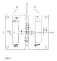
- Figure 1 illustrates a front view of an integral permanent magnet double core DC inductor according to the present invention.
- the inductor of the invention comprises two separate magnetic cores 1, 2 which both form a magnetic path by themselves.
- the magnetic path of the separate magnetic cores includes one or more magnetic gaps, i.e. air gaps 5, 6, 7, 8.
- the separate inductor structures may be operable as such as regular inductors or chokes.
- the separate inductors 1 and 2 are formed of two L-shaped structures 9, 10, 11, 12 forming side legs of the inductor and of modified T-shape structures 13, 14 forming a centre leg of the inductor.
- the centre leg is narrower in its open end and forms together with the shorter sides of the L-shaped structures the magnetic gaps.
- a winding or coil of the inductor is intended to be arranged on the centre legs 13, 14 of the separate inductors.
- permanent magnet pieces 3, 4 are arranged in magnetic gaps 16 and 17 between the separate inductors 1, 2 in such a manner that the at least one magnetic gap 5, 6, 7, 8 provided in the magnetic paths is between the permanent magnet pieces. In this way, a magnetic flux of the permanent magnets runs through the whole core structure as desired.
- the polarities of the permanent magnet pieces correspond to each other. This is to say that magnetic flux is produced with both permanent magnet pieces upwards in the drawing.
- the magnetic flux of the permanent magnets is shown by parallel arrows in Figure 1 .
- the flux runs from the permanent magnets 3 and 4 upwards in the legs 9 and 10, through the centre leg 13 and crossing a magnetic gap 15.
- the flux travels further after the magnetic gap 15 in the magnetic core 2 in a reverse order, i.e. through the centre leg 14 and closing the path through the side legs 11 and 12 to the permanent magnet pieces 3 and 4.
- the magnetic flux path obtainable by the coils is illustrated as longer and single arrows in Figure 1 .
- the flux can be considered as originating from the centre legs.
- the flux runs from the centre leg 13 and through the L-shaped side legs back to the centre leg.
- the flux formed in the upper inductor core stays in the same core.
- the inductor 2 the flux runs from centre leg 14 to side legs 11, 12 and returns back to centre core.
- the magnetic gap 15, which is between the centre legs of the two separate inductors, can be used as a magnetic coupling adjustor. As the fluxes produced by the coils in both of the centre cores flow in the same direction, part of those fluxes might couple through the magnetic gap 15.
- the permanent magnet pieces are not prone to demagnetization. Further, the flux from the coil of the inductor 2 supports the permanent magnet flux in the vicinity of the permanent magnet. In the L-shaped core structures 11, 12 below the permanent magnets in Figure 1 , the flux of the coil has the same general direction as that of the permanent magnets. On the other hand, above the permanent magnet pieces, in the vicinity of the magnets, the flux of the coil of the inductor 1 opposes the permanent magnet flux. This further eliminates the possibility of demagnetizing the permanent magnet.
- the integral permanent magnet double core DC inductor structure forms two chokes, i.e. a double pack.
- a single inductor can be substituted by two inductors having half the inductance of one. This is the case, for example, in connection with DC link chokes in a frequency converter.
- both rails of the DC link are equipped with inductors.
- the inductors are in series with each other when current enters the positive rail of the link and exits from the negative rail of the link.
- the integral permanent magnet double core DC inductor of the present invention is well suited for the above use, since the volume occupied by the inductor of the present invention is considerably smaller compared to that of two separate inductors having the same inductance. Further, when two similar separate cores are joined together by the permanent magnets, as in the present invention, the inductances for both core structures are the same.
- Figure 2 shows another embodiment of the present invention.
- the separate magnetic cores 31, 32 are formed of two L-shaped structures 35, 36, 37, 38.
- the coils or windings of the inductor are intended to be wound over legs formed from the structures 35 and 37.
- the embodiment of Figure 2 differs from the embodiment of Figure 1 in that there is no centre leg in Figure 2 .
- the magnetic flux produced by the permanent magnets circles around the whole structure (double arrows) clockwise and the permanent magnet pieces are arranged with differing polarities inside magnetic gaps 39, 40 between the separate inductors, i.e. the direction of magnetic flux from one permanent magnet piece 33 is up and from the other permanent magnet piece 34 down.
- the magnetic fluxes producible with the coils have a differing direction (single arrows) and these fluxes do not travel from one inductor core structure to another, but they close via magnetic gaps 41, 42.
- the flux from permanent magnets travels a route of the smallest reluctance, which is, as mentioned above, via the core structures of separate inductors with no magnetic gaps in the case of Figure 2 .
- the permanent magnet pieces are not prone to demagnetization.
- the flux from the coil of the inductor 32 supports the permanent magnet flux in the vicinity of the permanent magnet 33.
- the flux from the coil of the inductor 31 supports the permanent magnet flux in the vicinity of the permanent magnet 34. This further eliminates the possibility of demagnetizing the permanent magnet.
- Figure 3 shows another embodiment of the present invention similar to that of Figure 2 .
- separate core structures 51, 52 are formed of two L-shaped structures 55, 56, 57, 58.
- Permanent magnets 53, 54 are inserted in magnetic gaps 59, 60 between the two individual inductors 51 and 52.
- the windings are intended to be wound over legs, i.e. formed from structures 55 and 57.
- the magnetic fluxes producible by the windings circulate only in the respective separate structures of the individual inductors as indicated by the long arrows.
- the fluxes of the permanent magnets 53, 54 do not pass magnetic gaps 61, 62 provided in the individual core structures.
- the directions of the fluxes from the windings and from the permanent magnet pieces oppose each other. Therefore, the magnetic flux density in the core material is lowered.
- Figure 4 shows another embodiment of the present invention similar to that of Figure 3 , only instead of two separate permanent magnets a single piece magnet 79 is placed between the two separate chokes 71 and 72.
- the single piece permanent magnet is magnetised in two different directions, that is upwards and downwards.
- the functioning principle of the embodiment of Figure 4 is similar to that of Figure 3 .
- the same measures of permanent magnet protection as in the above cases apply.
- An inductance - current (L-I) curve of the inductors according to the present invention can be easily modified by using permanent magnet pieces of different physical dimensions with no need to make any modifications to the original chokes.
- the magnetic coupling, i.e. leakage flux, between the separate cores in the integral permanent magnet double core DC inductor structure is minimal, and can be further adjusted by modifying magnetic gaps and their position between and inside the separate inductor structures.
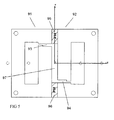
- Figure 5 shows an example in which the magnetic gaps inside the separate structures are moved such that magnetic gaps 93, 94 are not directly opposite to each other. This kind of positioning of the magnetic gaps greatly reduces the magnetic coupling between separate structures 91, 92.
- Thicker permanent magnet pieces 95, 96 also help to minimize the magnetic coupling between the separate structures since a gap 97 between the separate cores is larger.
- the magnetic gaps 93, 94 may be non-uniform, leading to swinging choke characteristics.
- the present invention enables the use of larger permanent magnets than the prior known solutions.
- the permanent magnets are shown as pieces occupying only a portion of the available space.
- the permanent magnet pieces may take the whole area between the opposing structures of the individual inductors. The larger the surface area of the permanent magnet pieces, the more flux from the permanent magnet pieces available. Thus the flux density inside the core structure can be kept at a low level for higher currents.
- the inductances of separate inductors are also the same.
- the structure of Figure 1 may have four separate coils wound on sides formed by the L-shaped structures 9, 10, 11, 12.
- the inductances of the coils are also the same.
- Figure 6 shows a permanent magnet holder which is used according to an embodiment of the invention to hold permanent magnets in place with respect to each other. Further, the holder protects the permanent magnets from mechanical impact by surrounding them.
- the permanent magnets are placed inside holder windows 101, 102, and free surfaces of the permanent magnets are placed towards inductor structures.
- the holder of Figure 6 can be used with structures shown in Figures 1 , 2 , 3 , and 5 . Two windows are separated from each other by a protrusion 103 which forms a gap between the magnets. The holder also helps in positioning the magnets precisely inside the structure.
- the core structures are defined as being L-shaped or T-shaped. It is, however, clear that the structure of the present invention can be achieved with other possibilities.
- the drawings presented are only examples of multiple possibilities of achieving the structure of the invention.
Landscapes
- Engineering & Computer Science (AREA)
- Power Engineering (AREA)
- Chemical & Material Sciences (AREA)
- Composite Materials (AREA)
- Coils Or Transformers For Communication (AREA)
Claims (10)
- Permanentmagnet-Gleichstromdrosselspule mit
mindestens zwei separaten und individuellen magnetischen Drosselspulen (1, 2; 31, 32; 51, 52; 71, 72; 91, 92), jede von denen ihre eigene Kernstruktur aufweist und geschlossene individuelle magnetische Wege ausbildet,
Wicklungen auf den magnetischen Kernen und
mindestens einem Permanentmagnetstück (3, 4; 33, 34; 53, 54; 79; 95, 96), worin die separaten magnetischen Kerne mit dem mindestens einen Magnetspalt (5, 6, 7, 8; 41, 42; 61, 62; 73, 74; 93, 94) gegeneinander angeordnet sind, indem äussere Magnetspalte (16, 17; 39, 40; 59, 60; 80, 81; 97) mit den innerhalb der äusseren Magnetspalte angeordneten Permanentmagnetstücken (3, 4; 33, 34; 53, 54; 79; 95, 96) ausgebildet werden, dadurch gekennzeichnet, dass
die geschlossenen individuellen magnetischen Wege mindestens einen Magnetspalt (5, 6, 7, 8; 41, 42; 61, 62; 73, 74; 93, 94) aufweisen
und das mindestens eine Permanentmagnetstück ferner auf beiden Seiten des mindestens einen Magnetspalts (5, 6, 7, 8; 41, 42; 61, 62; 73, 74; 93, 94) angeordnet ist. - Permanentmagnet-Gleichstromdrosselspule nach Anspruch 1, dadurch gekennzeichnet, dass die Drosselspule mindestens zwei Wicklungen aufweist und angeordnet ist, zwei separate induktive Komponenten auszubilden, die physikalisch und magnetisch durch den mindestens einen dazwischen befindlichen Permanentmagnet geschaltet sind.
- Permanentmagnet-Gleichstromdrosselspule nach Ansprüchen 1 und 2, dadurch gekennzeichnet, dass durch das mindestens eine Permanentmagnetstück erzeugte magnetische Flüsse angeordnet sind, in beiden separaten magnetischen Kernen zu fließen.
- Permanentmagnet-Gleichstromdrosselspule nach Ansprüchen 1, 2 oder 3, dadurch gekennzeichnet, dass ein durch mindestens eine der Wicklungen einer individuellen Drosselspule erzeugter magnetischer Fluss einen durch mindestens einen der Permanentmagnete erzeugten magnetischen Fluss teilweise unterstützt.
- Permanentmagnet-Gleichstromdrosselspule nach einem der Ansprüche 1 bis 4, dadurch gekennzeichnet, dass die durch das mindestens eine Permanentmagnetstück erzeugten magnetischen Flüsse angerordnet sind, einem mit den Wicklungen von zwei individuellen Kernen erzeugbaren magnetischen Fluss zu widerstehen.
- Permanentmagnet-Gleichstromdrosselspule nach einem der Ansprüche 1 bis 5, dadurch gekennzeichnet, dass die innerhalb der individuellen Drosselspulen befindlichen Magnetspalte nicht unbedingt einander direkt gegenüber liegen.
- Permanentmagnet-Gleichstromdrosselspule nach einem der Ansprüche 1 bis 6, dadurch gekennzeichnet, dass die innerhalb der individuellen Drosselspulen befindlichen Magnetspalte nicht unbedingt eine gleichmäßige Form aufweisen.
- Permanentmagnet-Gleichstromdrosselspule nach einem der vorhergehenden Ansprüche 1 bis 7, dadurch gekennzeichnet, dass die separaten magnetischen Kerne Seitenschenkel (9, 10; 11, 12), einen die Schenkel verbindenden T-förmigen mittleren Schenkel (13; 14) aufweisen, wobei der durch die Permanentmagnetstücke erzeugte Fluss über die Seitenschenkel und die mittleren Schenkel der beiden separaten magnetischen Kerne fließt und der durch die Wicklungen erzeugbare Fluss in den separaten Kernstrukturen fließt, in denen die entsprechenden Wicklungen angeordnet sind.
- Permanentmagnet-Gleichstromdrosselspule nach einem der vorhergehenden Ansprüche 1 bis 8, dadurch gekennzeichnet, dass die separaten magnetischen Kerne Seitenschenkel (35, 36; 37, 38) aufweisen, wobei der durch das mindestens eine Permanentmagnetstück erzeugte Fluss über die Seitenschenkel der beiden separaten magnetischen Kerne fließt und der mit den Wicklungen erzeugbare Fluss in den separaten Kernstrukturen fließt, in denen die entsprechenden Wicklungen angeordnet sind.
- Permanentmagnet-Gleichstromdrosselspule nach einem der vorhergehenden Ansprüche 1 bis 9, dadurch gekennzeichnet, dass die Permanentmagnet-Gleichstromdrosselspule einen Magnethalter (89) zum Halten der Permanentmagnetstücke aufweist, welcher Halter adaptiert ist, die Permanentmagnetstücke mindestens teilweise zu umgeben und die Magnete in Bezug aufeinander in Position zu halten.
Priority Applications (4)
| Application Number | Priority Date | Filing Date | Title |
|---|---|---|---|
| EP09152140A EP2216794B1 (de) | 2009-02-05 | 2009-02-05 | Permanentmagnet-Gleichstromdrosselspule |
| AT09152140T ATE531055T1 (de) | 2009-02-05 | 2009-02-05 | Permanentmagnet-gleichstromdrosselspule |
| CN200910145592.5A CN101800114B (zh) | 2009-02-05 | 2009-06-03 | 永磁直流电感器 |
| US12/700,252 US9030282B2 (en) | 2009-02-05 | 2010-02-04 | Permanent magnet DC inductor |
Applications Claiming Priority (1)
| Application Number | Priority Date | Filing Date | Title |
|---|---|---|---|
| EP09152140A EP2216794B1 (de) | 2009-02-05 | 2009-02-05 | Permanentmagnet-Gleichstromdrosselspule |
Publications (2)
| Publication Number | Publication Date |
|---|---|
| EP2216794A1 EP2216794A1 (de) | 2010-08-11 |
| EP2216794B1 true EP2216794B1 (de) | 2011-10-26 |
Family
ID=40688190
Family Applications (1)
| Application Number | Title | Priority Date | Filing Date |
|---|---|---|---|
| EP09152140A Active EP2216794B1 (de) | 2009-02-05 | 2009-02-05 | Permanentmagnet-Gleichstromdrosselspule |
Country Status (4)
| Country | Link |
|---|---|
| US (1) | US9030282B2 (de) |
| EP (1) | EP2216794B1 (de) |
| CN (1) | CN101800114B (de) |
| AT (1) | ATE531055T1 (de) |
Families Citing this family (14)
| Publication number | Priority date | Publication date | Assignee | Title |
|---|---|---|---|---|
| CA2715918A1 (en) * | 2008-02-22 | 2009-08-27 | Access Business Group International Llc | Magnetic positioning for inductive coupling |
| TWI451458B (zh) * | 2009-08-25 | 2014-09-01 | Access Business Group Int Llc | 磁通量集中器及製造一磁通量集中器的方法 |
| WO2011130905A1 (zh) * | 2010-04-20 | 2011-10-27 | 安阳安科电器股份有限公司 | 脉冲电流传感器及采用该传感器制成的记录电涌波防雷箱 |
| JP5440719B2 (ja) * | 2011-01-26 | 2014-03-12 | トヨタ自動車株式会社 | リアクトル及びリアクトル装置 |
| CN106716563A (zh) * | 2014-09-24 | 2017-05-24 | Hiq太阳能股份有限公司 | 双间隙感应器的新颖构造 |
| US9905353B2 (en) * | 2014-09-24 | 2018-02-27 | Hiq Solar, Inc. | Construction of double gap inductor |
| FR3045924B1 (fr) * | 2015-12-17 | 2021-05-07 | Commissariat Energie Atomique | Noyau d'inductance a pertes magnetiques reduites |
| CN106373766B (zh) * | 2016-10-20 | 2019-08-16 | Tcl通力电子(惠州)有限公司 | 非线性磁性器件及其制造方法 |
| DE102018112100A1 (de) * | 2018-05-18 | 2019-12-05 | Tdk Electronics Ag | Drossel mit hoher Gleichtaktinduktivität |
| JP7320748B2 (ja) * | 2019-06-21 | 2023-08-04 | パナソニックIpマネジメント株式会社 | コア |
| JP7425962B2 (ja) * | 2019-12-23 | 2024-02-01 | Tdk株式会社 | コイル部品 |
| WO2022060876A1 (en) * | 2020-09-17 | 2022-03-24 | Mte Corporation | Adjustable multi-gapped combined common mode and differential mode three phase inductors and methods of manufacture and use thereof |
| CN113643881A (zh) * | 2021-08-09 | 2021-11-12 | 东南大学 | 一种具有并联磁路的永磁偏置电感调谐装置及方法 |
| KR20250165910A (ko) * | 2024-05-20 | 2025-11-27 | 삼성전자주식회사 | 바이어스 자석을 채용한 인덕터를 포함하는 가전장치 |
Family Cites Families (14)
| Publication number | Priority date | Publication date | Assignee | Title |
|---|---|---|---|---|
| US2860313A (en) * | 1953-09-04 | 1958-11-11 | Emerson Radio And Phonograph C | Inductive tuning device |
| US4533890A (en) * | 1984-12-24 | 1985-08-06 | General Motors Corporation | Permanent magnet bistable solenoid actuator |
| US4928028A (en) * | 1989-02-23 | 1990-05-22 | Hydraulic Units, Inc. | Proportional permanent magnet force actuator |
| CA2145691A1 (en) * | 1993-12-08 | 1996-09-29 | Stephen B. Kuznetsov | Method and apparatus for limiting high current electrical faults in distribution networks by use of superconducting excitation in transverse flux magnetic circuit |
| JP3230647B2 (ja) * | 1994-12-09 | 2001-11-19 | 株式会社安川電機 | 直流リアクトル |
| US6066998A (en) * | 1996-09-12 | 2000-05-23 | Massachusetts Institute Of Technology | Magnetic actuator with long travel in one direction |
| US6778056B2 (en) * | 2000-08-04 | 2004-08-17 | Nec Tokin Corporation | Inductance component having a permanent magnet in the vicinity of a magnetic gap |
| JP3723174B2 (ja) * | 2002-11-15 | 2005-12-07 | 三菱電機株式会社 | 操作装置、操作装置の製造方法及びこの操作装置を備えた開閉装置 |
| FR2851290B1 (fr) * | 2003-02-18 | 2007-02-09 | Peugeot Citroen Automobiles Sa | Actionneur electromecanique de commande de soupape pour moteur a combustion interne |
| DE102004010404A1 (de) * | 2004-03-03 | 2005-09-22 | BSH Bosch und Siemens Hausgeräte GmbH | Lineare Antriebseinrichtung mit einem einen Magnetträger aufweisenden Ankerkörper |
| JP2006222387A (ja) * | 2005-02-14 | 2006-08-24 | Toshiba Corp | チョークコイル装置 |
| US7518269B2 (en) * | 2005-03-18 | 2009-04-14 | Ls Industrial Systems Co., Ltd. | Actuator using permanent magnet |
| JP2007123596A (ja) | 2005-10-28 | 2007-05-17 | Yaskawa Electric Corp | 直流リアクトルおよびインバータ装置 |
| FI122086B (fi) * | 2007-07-06 | 2011-08-15 | Vacon Oyj | Suotokuristinjärjestely |
-
2009
- 2009-02-05 AT AT09152140T patent/ATE531055T1/de not_active IP Right Cessation
- 2009-02-05 EP EP09152140A patent/EP2216794B1/de active Active
- 2009-06-03 CN CN200910145592.5A patent/CN101800114B/zh active Active
-
2010
- 2010-02-04 US US12/700,252 patent/US9030282B2/en active Active
Also Published As
| Publication number | Publication date |
|---|---|
| EP2216794A1 (de) | 2010-08-11 |
| ATE531055T1 (de) | 2011-11-15 |
| CN101800114A (zh) | 2010-08-11 |
| US9030282B2 (en) | 2015-05-12 |
| CN101800114B (zh) | 2012-11-28 |
| US20100194512A1 (en) | 2010-08-05 |
Similar Documents
| Publication | Publication Date | Title |
|---|---|---|
| US9030282B2 (en) | Permanent magnet DC inductor | |
| US11587726B2 (en) | Coupled inductor structure | |
| JP5689338B2 (ja) | リアクトル装置、およびこのリアクトル装置を用いた電力変換装置 | |
| JP5631487B2 (ja) | 低高調波の3相受電機器用の統合型磁気デバイス及び低高調波の双方向式受電側3相電力変換器 | |
| EP2001029B1 (de) | Gleichstrominduktor | |
| US9251941B2 (en) | Transformer | |
| CN106057395A (zh) | 一种具有永磁偏磁的磁性元件组合体及其实现方法 | |
| US11205537B2 (en) | Magnetic component, resonant electrical circuit, electrical converter and electrical system | |
| CN110832607A (zh) | 存储器扼流圈 | |
| US8902032B2 (en) | Induction device | |
| JP2007123596A (ja) | 直流リアクトルおよびインバータ装置 | |
| CN205943635U (zh) | 一种具有永磁偏磁的磁性元件组合体 | |
| EP2117020A1 (de) | Reaktoranordnung für Wechselstrom | |
| JP4193942B2 (ja) | インダクタンス部品 | |
| CN104021919A (zh) | 用于滤波电感器的块状组合磁芯 | |
| US12131864B2 (en) | Transformer with integral inductor | |
| JP4193943B2 (ja) | インダクタンス部品 | |
| JP2004055787A5 (de) | ||
| JP2006108390A (ja) | トランスコア及びこれを用いたリーケージトランス | |
| JP2007281204A (ja) | 直流リアクトル | |
| JP2005039965A (ja) | 限流器 | |
| JP5846864B2 (ja) | バイアス励磁トランス及び電気回路 | |
| JP4197327B2 (ja) | インダクタンス部品 | |
| CN102543376A (zh) | 一种led用差模扼流圈磁心 | |
| JP2006108392A (ja) | リーケージトランス |
Legal Events
| Date | Code | Title | Description |
|---|---|---|---|
| PUAI | Public reference made under article 153(3) epc to a published international application that has entered the european phase |
Free format text: ORIGINAL CODE: 0009012 |
|
| AK | Designated contracting states |
Kind code of ref document: A1 Designated state(s): AT BE BG CH CY CZ DE DK EE ES FI FR GB GR HR HU IE IS IT LI LT LU LV MC MK MT NL NO PL PT RO SE SI SK TR |
|
| AX | Request for extension of the european patent |
Extension state: AL BA RS |
|
| 17P | Request for examination filed |
Effective date: 20100922 |
|
| 17Q | First examination report despatched |
Effective date: 20101111 |
|
| AKX | Designation fees paid |
Designated state(s): AT BE BG CH CY CZ DE DK EE ES FI FR GB GR HR HU IE IS IT LI LT LU LV MC MK MT NL NO PL PT RO SE SI SK TR |
|
| GRAP | Despatch of communication of intention to grant a patent |
Free format text: ORIGINAL CODE: EPIDOSNIGR1 |
|
| GRAS | Grant fee paid |
Free format text: ORIGINAL CODE: EPIDOSNIGR3 |
|
| GRAA | (expected) grant |
Free format text: ORIGINAL CODE: 0009210 |
|
| AK | Designated contracting states |
Kind code of ref document: B1 Designated state(s): AT BE BG CH CY CZ DE DK EE ES FI FR GB GR HR HU IE IS IT LI LT LU LV MC MK MT NL NO PL PT RO SE SI SK TR |
|
| REG | Reference to a national code |
Ref country code: GB Ref legal event code: FG4D |
|
| REG | Reference to a national code |
Ref country code: CH Ref legal event code: EP |
|
| REG | Reference to a national code |
Ref country code: IE Ref legal event code: FG4D |
|
| REG | Reference to a national code |
Ref country code: DE Ref legal event code: R096 Ref document number: 602009003236 Country of ref document: DE Effective date: 20111229 |
|
| REG | Reference to a national code |
Ref country code: NL Ref legal event code: VDEP Effective date: 20111026 |
|
| LTIE | Lt: invalidation of european patent or patent extension |
Effective date: 20111026 |
|
| REG | Reference to a national code |
Ref country code: AT Ref legal event code: MK05 Ref document number: 531055 Country of ref document: AT Kind code of ref document: T Effective date: 20111026 |
|
| PG25 | Lapsed in a contracting state [announced via postgrant information from national office to epo] |
Ref country code: BE Free format text: LAPSE BECAUSE OF FAILURE TO SUBMIT A TRANSLATION OF THE DESCRIPTION OR TO PAY THE FEE WITHIN THE PRESCRIBED TIME-LIMIT Effective date: 20111026 Ref country code: LT Free format text: LAPSE BECAUSE OF FAILURE TO SUBMIT A TRANSLATION OF THE DESCRIPTION OR TO PAY THE FEE WITHIN THE PRESCRIBED TIME-LIMIT Effective date: 20111026 Ref country code: NO Free format text: LAPSE BECAUSE OF FAILURE TO SUBMIT A TRANSLATION OF THE DESCRIPTION OR TO PAY THE FEE WITHIN THE PRESCRIBED TIME-LIMIT Effective date: 20120126 Ref country code: IS Free format text: LAPSE BECAUSE OF FAILURE TO SUBMIT A TRANSLATION OF THE DESCRIPTION OR TO PAY THE FEE WITHIN THE PRESCRIBED TIME-LIMIT Effective date: 20120226 |
|
| PG25 | Lapsed in a contracting state [announced via postgrant information from national office to epo] |
Ref country code: GR Free format text: LAPSE BECAUSE OF FAILURE TO SUBMIT A TRANSLATION OF THE DESCRIPTION OR TO PAY THE FEE WITHIN THE PRESCRIBED TIME-LIMIT Effective date: 20120127 Ref country code: SE Free format text: LAPSE BECAUSE OF FAILURE TO SUBMIT A TRANSLATION OF THE DESCRIPTION OR TO PAY THE FEE WITHIN THE PRESCRIBED TIME-LIMIT Effective date: 20111026 Ref country code: PT Free format text: LAPSE BECAUSE OF FAILURE TO SUBMIT A TRANSLATION OF THE DESCRIPTION OR TO PAY THE FEE WITHIN THE PRESCRIBED TIME-LIMIT Effective date: 20120227 Ref country code: SI Free format text: LAPSE BECAUSE OF FAILURE TO SUBMIT A TRANSLATION OF THE DESCRIPTION OR TO PAY THE FEE WITHIN THE PRESCRIBED TIME-LIMIT Effective date: 20111026 Ref country code: NL Free format text: LAPSE BECAUSE OF FAILURE TO SUBMIT A TRANSLATION OF THE DESCRIPTION OR TO PAY THE FEE WITHIN THE PRESCRIBED TIME-LIMIT Effective date: 20111026 Ref country code: LV Free format text: LAPSE BECAUSE OF FAILURE TO SUBMIT A TRANSLATION OF THE DESCRIPTION OR TO PAY THE FEE WITHIN THE PRESCRIBED TIME-LIMIT Effective date: 20111026 Ref country code: HR Free format text: LAPSE BECAUSE OF FAILURE TO SUBMIT A TRANSLATION OF THE DESCRIPTION OR TO PAY THE FEE WITHIN THE PRESCRIBED TIME-LIMIT Effective date: 20111026 Ref country code: PL Free format text: LAPSE BECAUSE OF FAILURE TO SUBMIT A TRANSLATION OF THE DESCRIPTION OR TO PAY THE FEE WITHIN THE PRESCRIBED TIME-LIMIT Effective date: 20111026 |
|
| PG25 | Lapsed in a contracting state [announced via postgrant information from national office to epo] |
Ref country code: CY Free format text: LAPSE BECAUSE OF FAILURE TO SUBMIT A TRANSLATION OF THE DESCRIPTION OR TO PAY THE FEE WITHIN THE PRESCRIBED TIME-LIMIT Effective date: 20111026 |
|
| PG25 | Lapsed in a contracting state [announced via postgrant information from national office to epo] |
Ref country code: BG Free format text: LAPSE BECAUSE OF FAILURE TO SUBMIT A TRANSLATION OF THE DESCRIPTION OR TO PAY THE FEE WITHIN THE PRESCRIBED TIME-LIMIT Effective date: 20120126 Ref country code: DK Free format text: LAPSE BECAUSE OF FAILURE TO SUBMIT A TRANSLATION OF THE DESCRIPTION OR TO PAY THE FEE WITHIN THE PRESCRIBED TIME-LIMIT Effective date: 20111026 Ref country code: CZ Free format text: LAPSE BECAUSE OF FAILURE TO SUBMIT A TRANSLATION OF THE DESCRIPTION OR TO PAY THE FEE WITHIN THE PRESCRIBED TIME-LIMIT Effective date: 20111026 Ref country code: SK Free format text: LAPSE BECAUSE OF FAILURE TO SUBMIT A TRANSLATION OF THE DESCRIPTION OR TO PAY THE FEE WITHIN THE PRESCRIBED TIME-LIMIT Effective date: 20111026 Ref country code: EE Free format text: LAPSE BECAUSE OF FAILURE TO SUBMIT A TRANSLATION OF THE DESCRIPTION OR TO PAY THE FEE WITHIN THE PRESCRIBED TIME-LIMIT Effective date: 20111026 |
|
| PG25 | Lapsed in a contracting state [announced via postgrant information from national office to epo] |
Ref country code: RO Free format text: LAPSE BECAUSE OF FAILURE TO SUBMIT A TRANSLATION OF THE DESCRIPTION OR TO PAY THE FEE WITHIN THE PRESCRIBED TIME-LIMIT Effective date: 20111026 |
|
| PLBE | No opposition filed within time limit |
Free format text: ORIGINAL CODE: 0009261 |
|
| STAA | Information on the status of an ep patent application or granted ep patent |
Free format text: STATUS: NO OPPOSITION FILED WITHIN TIME LIMIT |
|
| PG25 | Lapsed in a contracting state [announced via postgrant information from national office to epo] |
Ref country code: MC Free format text: LAPSE BECAUSE OF NON-PAYMENT OF DUE FEES Effective date: 20120229 |
|
| 26N | No opposition filed |
Effective date: 20120727 |
|
| REG | Reference to a national code |
Ref country code: IE Ref legal event code: MM4A |
|
| REG | Reference to a national code |
Ref country code: DE Ref legal event code: R097 Ref document number: 602009003236 Country of ref document: DE Effective date: 20120727 |
|
| PG25 | Lapsed in a contracting state [announced via postgrant information from national office to epo] |
Ref country code: AT Free format text: LAPSE BECAUSE OF FAILURE TO SUBMIT A TRANSLATION OF THE DESCRIPTION OR TO PAY THE FEE WITHIN THE PRESCRIBED TIME-LIMIT Effective date: 20111026 Ref country code: IE Free format text: LAPSE BECAUSE OF NON-PAYMENT OF DUE FEES Effective date: 20120205 |
|
| PG25 | Lapsed in a contracting state [announced via postgrant information from national office to epo] |
Ref country code: MK Free format text: LAPSE BECAUSE OF FAILURE TO SUBMIT A TRANSLATION OF THE DESCRIPTION OR TO PAY THE FEE WITHIN THE PRESCRIBED TIME-LIMIT Effective date: 20111026 |
|
| PG25 | Lapsed in a contracting state [announced via postgrant information from national office to epo] |
Ref country code: ES Free format text: LAPSE BECAUSE OF FAILURE TO SUBMIT A TRANSLATION OF THE DESCRIPTION OR TO PAY THE FEE WITHIN THE PRESCRIBED TIME-LIMIT Effective date: 20120206 |
|
| PG25 | Lapsed in a contracting state [announced via postgrant information from national office to epo] |
Ref country code: MT Free format text: LAPSE BECAUSE OF FAILURE TO SUBMIT A TRANSLATION OF THE DESCRIPTION OR TO PAY THE FEE WITHIN THE PRESCRIBED TIME-LIMIT Effective date: 20111026 |
|
| REG | Reference to a national code |
Ref country code: CH Ref legal event code: PL |
|
| PG25 | Lapsed in a contracting state [announced via postgrant information from national office to epo] |
Ref country code: CH Free format text: LAPSE BECAUSE OF NON-PAYMENT OF DUE FEES Effective date: 20130228 Ref country code: LI Free format text: LAPSE BECAUSE OF NON-PAYMENT OF DUE FEES Effective date: 20130228 |
|
| PG25 | Lapsed in a contracting state [announced via postgrant information from national office to epo] |
Ref country code: TR Free format text: LAPSE BECAUSE OF FAILURE TO SUBMIT A TRANSLATION OF THE DESCRIPTION OR TO PAY THE FEE WITHIN THE PRESCRIBED TIME-LIMIT Effective date: 20111026 |
|
| PG25 | Lapsed in a contracting state [announced via postgrant information from national office to epo] |
Ref country code: LU Free format text: LAPSE BECAUSE OF NON-PAYMENT OF DUE FEES Effective date: 20120205 |
|
| PG25 | Lapsed in a contracting state [announced via postgrant information from national office to epo] |
Ref country code: HU Free format text: LAPSE BECAUSE OF FAILURE TO SUBMIT A TRANSLATION OF THE DESCRIPTION OR TO PAY THE FEE WITHIN THE PRESCRIBED TIME-LIMIT Effective date: 20090205 |
|
| REG | Reference to a national code |
Ref country code: FR Ref legal event code: PLFP Year of fee payment: 8 |
|
| REG | Reference to a national code |
Ref country code: FR Ref legal event code: PLFP Year of fee payment: 9 |
|
| REG | Reference to a national code |
Ref country code: FR Ref legal event code: PLFP Year of fee payment: 10 |
|
| REG | Reference to a national code |
Ref country code: GB Ref legal event code: 732E Free format text: REGISTERED BETWEEN 20180823 AND 20180829 |
|
| REG | Reference to a national code |
Ref country code: DE Ref legal event code: R081 Ref document number: 602009003236 Country of ref document: DE Owner name: ABB SCHWEIZ AG, CH Free format text: FORMER OWNER: ABB OY, HELSINKI, FI |
|
| PGFP | Annual fee paid to national office [announced via postgrant information from national office to epo] |
Ref country code: DE Payment date: 20250218 Year of fee payment: 17 |
|
| PGFP | Annual fee paid to national office [announced via postgrant information from national office to epo] |
Ref country code: FI Payment date: 20250218 Year of fee payment: 17 |
|
| PGFP | Annual fee paid to national office [announced via postgrant information from national office to epo] |
Ref country code: FR Payment date: 20250221 Year of fee payment: 17 |
|
| PGFP | Annual fee paid to national office [announced via postgrant information from national office to epo] |
Ref country code: IT Payment date: 20250224 Year of fee payment: 17 Ref country code: GB Payment date: 20250219 Year of fee payment: 17 |