EP2216867A2 - Dichtung, Gehäuse mit der Dichtung und Verfahren zum Einführen eines Glasfaserkabels in das Gehäuse - Google Patents
Dichtung, Gehäuse mit der Dichtung und Verfahren zum Einführen eines Glasfaserkabels in das Gehäuse Download PDFInfo
- Publication number
- EP2216867A2 EP2216867A2 EP10153161A EP10153161A EP2216867A2 EP 2216867 A2 EP2216867 A2 EP 2216867A2 EP 10153161 A EP10153161 A EP 10153161A EP 10153161 A EP10153161 A EP 10153161A EP 2216867 A2 EP2216867 A2 EP 2216867A2
- Authority
- EP
- European Patent Office
- Prior art keywords
- seal
- enclosure
- hole
- optical fibre
- cable
- Prior art date
- Legal status (The legal status is an assumption and is not a legal conclusion. Google has not performed a legal analysis and makes no representation as to the accuracy of the status listed.)
- Withdrawn
Links
Images

Classifications
-
- H—ELECTRICITY
- H02—GENERATION; CONVERSION OR DISTRIBUTION OF ELECTRIC POWER
- H02G—INSTALLATION OF ELECTRIC CABLES OR LINES, OR OF COMBINED OPTICAL AND ELECTRIC CABLES OR LINES
- H02G15/00—Cable fittings
- H02G15/013—Sealing means for cable inlets
-
- H—ELECTRICITY
- H02—GENERATION; CONVERSION OR DISTRIBUTION OF ELECTRIC POWER
- H02G—INSTALLATION OF ELECTRIC CABLES OR LINES, OR OF COMBINED OPTICAL AND ELECTRIC CABLES OR LINES
- H02G3/00—Installations of electric cables or lines or protective tubing therefor in or on buildings, equivalent structures or vehicles
- H02G3/02—Details
- H02G3/08—Distribution boxes; Connection or junction boxes
- H02G3/081—Bases, casings or covers
- H02G3/083—Inlets
- H02G3/085—Inlets including knock-out or tear-out sections
-
- G—PHYSICS
- G02—OPTICS
- G02B—OPTICAL ELEMENTS, SYSTEMS OR APPARATUS
- G02B6/00—Light guides; Structural details of arrangements comprising light guides and other optical elements, e.g. couplings
- G02B6/44—Mechanical structures for providing tensile strength and external protection for fibres, e.g. optical transmission cables
- G02B6/4439—Auxiliary devices
- G02B6/444—Systems or boxes with surplus lengths
- G02B6/4441—Boxes
- G02B6/4446—Cable boxes, e.g. splicing boxes with two or more multi fibre cables
- G02B6/44465—Seals
-
- G—PHYSICS
- G02—OPTICS
- G02B—OPTICAL ELEMENTS, SYSTEMS OR APPARATUS
- G02B6/00—Light guides; Structural details of arrangements comprising light guides and other optical elements, e.g. couplings
- G02B6/44—Mechanical structures for providing tensile strength and external protection for fibres, e.g. optical transmission cables
- G02B6/4439—Auxiliary devices
- G02B6/4471—Terminating devices ; Cable clamps
- G02B6/44775—Cable seals e.g. feed-through
-
- G—PHYSICS
- G02—OPTICS
- G02B—OPTICAL ELEMENTS, SYSTEMS OR APPARATUS
- G02B6/00—Light guides; Structural details of arrangements comprising light guides and other optical elements, e.g. couplings
- G02B6/46—Processes or apparatus adapted for installing or repairing optical fibres or optical cables
- G02B6/47—Installation in buildings
-
- H—ELECTRICITY
- H02—GENERATION; CONVERSION OR DISTRIBUTION OF ELECTRIC POWER
- H02G—INSTALLATION OF ELECTRIC CABLES OR LINES, OR OF COMBINED OPTICAL AND ELECTRIC CABLES OR LINES
- H02G3/00—Installations of electric cables or lines or protective tubing therefor in or on buildings, equivalent structures or vehicles
- H02G3/02—Details
- H02G3/08—Distribution boxes; Connection or junction boxes
- H02G3/088—Dustproof, splashproof, drip-proof, waterproof, or flameproof casings or inlets
Definitions
- the invention relates to a seal for sealably receiving an elongated object. More specifically, the invention relates to a flexible planar seal which is claimed in the preamble of the attached claim 1 and is particularly suitable for receiving cables and pipes and sealing them at through holes in walls of different structures, such as enclosures.
- a significant problem is also that the optical properties of the optical fibre at the connecting point are not comparable to those of the optical fibre without a splice: the splice causes undesired reflections, which attenuate the signal to be transmitted. This causes problems in transferring a television signal, for instance.
- Publication BE 621632 discloses a flexible planar seal as claimed in the preamble of claim 1.
- the seal allows the insertion of a cable into a through hole of the seal by first breaking a weakening film at the through hole of the seal.
- the cable is led into the seal in the longitudinal direction of the cable and in a direction perpendicular to the plane defined by the seal.
- the invention also relates to an enclosure for cables, particularly optical fibre cables.
- Publication FI 119040B discloses an enclosure with a split seal.
- the seal allows the insertion of a cable into the enclosure by leading the cable laterally to the through hole of the seal.
- the invention further relates to a method for inserting an optical fibre cable into an optical fibre cable enclosure from a first through hole of the enclosure and guiding it out of the enclosure from a second through hole, and sealing an optical fibre cable against the surroundings outside the enclosure.
- the seal according to the invention is characterized in that the sealing material between the seal's outer circumference and the weakening film defines a lateral access for the elongated object from the outer circumference to the through hole to bring the elongated object in a lateral direction to the through hole from the outer circumference of the seal and perpendicularly to the longitudinal direction of the elongated object, after the sealing material in the weakening region has been broken.
- the seal Since the seal has a tapering shape, it is very easy to mount it in its place.
- An easy way to form a weakening region in the sealing material is to provide the sealing material with one or more weakening cuts.
- the greatest advantage of the seal according to the invention is that, in every installation and application, it makes it easy to insert an elongated object to the through hole of the seal and have it surrounded by the through hole. It is thus possible to use the same seal at different objects, which also improves the logistics and abolishes the need for storing seals with different kinds of structures.
- the enclosure of the invention is characterized by what is disclosed in the attached claim 9.
- a groove in the enclosure is preferably arranged to taper towards the bottom part of the enclosure in order to receive a seal having a tapering shape.
- the enclosure comprises a second through hole, which is defined by a groove, which is open towards the cover of the enclosure and arranged to receive a second flexible planar seal for receiving a cable.
- a second through hole which is defined by a groove, which is open towards the cover of the enclosure and arranged to receive a second flexible planar seal for receiving a cable.
- the greatest advantage of the enclosure according to the invention is that it makes it easy in every situation and application, including optical fibre cable applications, to insert an elongated object to the through hole of the seal and to seal the cable.
- the method of the invention is characterized by what is disclosed in the characterizing part of the attached claim 12.
- the preferred embodiment of the method is disclosed in the attached claim 13.
- the greatest advantage of the method according to the invention is that it allows the installation of an optical fibre cable in an optical fibre cable enclosure without needing to cut the optical fibre cable, which also means that there is no need to form a plurality of splices to connect the optical fibres contained in the cables back together. This also makes it possible to avoid the deterioration of light transmission properties of optical fibres.
- Figure 1 shows a prior art arrangement for installing an optical fibre cable 3' in an optical fibre cable enclosure.
- the figure only shows a bottom part 13' of the optical fibre cable enclosure together with its O-rings 15a' and 15b', and the optical fibre cable 3' with its splices 40', which connect the various optical fibres of the optical fibre cable together.
- the cover of the enclosure, which is to be set tightly onto the bottom part 13', is not shown.
- the seals 15a', 15b' are installed at through holes 16a', 16b' in a wall structure 17' of the bottom part 13'.
- Reference numeral 30' refers to optical fibres, which are split/separated from the optical fibre cable 3' and exit the enclosure and which area inserted to a desired object, i.e.
- the object is the data system of the building.
- the building is a block of flats, for example.
- the number of optical fibres 30' inserted to a data system of a building is typically only a small fraction of the number of optical fibres contained in the optical fibre cable 3'.
- the optical fibre cable 3' enters the enclosure through the seal 15a' and passes through the seal 15b' to another building.
- the cable 3' passing through the seal 15b' contains a smaller number of optical fibres than the cable 3' passing through the seal 15a'.
- the cables 3' passing through the seals 15a', 15b' are the same cable. It is made of the same cable which is cut in order to install it inside the enclosure and to separate a few sparse optical fibres 30 to be led to a desired object, after which the optical fibres of the cable are melt back together to form a plurality of connecting points or splices 40'.
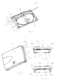
- Figures 2 to 4 show an optical fibre cable enclosure of the invention from different angles.
- the enclosure comprises a bottom part 13 with a bottom 18 and a wall structure extending upwards therefrom and making the bottom part look like a trough.
- the wall structure 17 of the bottom part which is behind the enclosure and from which a part is shown in Figure 5 on an enlarged scale, comprises two through holes 16a, 16b, at which seals 15a, 15b are installed, cf.
- Figure 4 show that the front part of the enclosure has a similar wall structure 21 with two through holes 16c, 16d. For the sake of simplicity, no seals are drawn at the through holes 16c, 16d, but similar seals 15a, 15b can be used there as in the wall structure 17.
- the cover 14 of the enclosure is trough-shaped and set sealably against the bottom part 13 when all through holes 16a to 16d in the bottom part are provided with seals.
- its lower edge 20 is pressed against the straight upper edge of the seals 15a, 15b, forming a straight circumferential section 19 so that the seals are pressed inside the grooves 16a to 16d defining the through holes, thus providing a compact enclosure.
- the seals 15a, 15b are a bit larger than the grooves 16a, 16b provided for them, which provides a pressing effect.
- the seals 15a, 15b are also set sealably around the cable 3' installed inside them, which leads to an entity consisting of the enclosure, seals and cables and having an IP code of IP54, for instance.
- the seals 15a, 15b are made of a flexible material, preferably EPDM material. This material is particularly suitable, since the seals must yield well but they must also be capable of being broken, which is discussed hereinafter.
- Inside the enclosure there are one or more cassettes (not shown) for receiving optical fibres.
- FIG 5 illustrates the installation of the cable 3 in the enclosure.
- the cable 3 seems cut but in the solution of the invention this is not the case; it only deals herein with a simplification carried out in the drawing.
- the cable 3 is installed in the through hole of the seal 15a, where it is surrounded by a wall 4 sealing the seal.
- the sealing wall 4 comprises an annular sealing section 8, which can be seen in Figure 6 showing an individual seal 15a.
- the seal 15a also comprises a second sealing annular section 9 that is further inside the seal.
- the latter has a smaller diameter than the former, wherefore the seal 15a may receive cables with greatly different diameters. Due to two annular sections 8, 9 the tightness reliability can be improved when both of them surround the cable tightly.
- the diameters of the annular sections 8, 9 must naturally be selected in such a manner that a desired effect, i.e. suitability for cables with different diameters or a better sealing, will be achieved.
- the cable 3 and its seals 15a are lowered down to a receiving groove 16a in the bottom part 13 of the enclosure.
- the groove 16a and the seal 15a have the same tapering shape and are thus wedge-shaped.
- the seal 15a tapers towards the bottom 18 of the bottom part; accordingly, the groove 16a widens in a direction away from the bottom part 13, i.e. towards the cover 14 to be set onto the bottom part 13, cf. Figure 4 .
- the cable 3 and its seals 15b are installed in the groove 16b, cf. Figure 4 . Because of the tapering shape the installation is easy.
- the installation of the cable 3 does not mean it must be cut but it is sufficient to only break its sheath and then break only one optical fibre or a few optical fibres from the plurality of optical fibres in the cable so that a desired number of optical fibres can be inserted into the object. In this way, many unnecessary cuttings and splices of optical fibres can be avoided, unlike in the known solution of Figure 1 .
- the through holes are formed near the bottom 18 of the bottom part 13, because the cable 3 has to be set close to the bottom 18.
- Figures 6 to 11 show a seal 15a, which is utilized in the installation of the cable 3 according to the invention.
- the figures show the seal from behind as a perspective view, from the top, from below, from both sides, and as a front perspective view.
- the seal 15a is planar and flexible. In the middle of the seal 15a there is a through hole 2, to which the cable 3 is intended to be set. In the central region of the through hole 2 there is an annular weakening film 5 (cf. Figures 6 and 11 ), where the thickness of the sealing material is relatively small so as to allow its easy breaking. In the region between the outer circumference 1 of the seal 15a and the weakening film 5 there is a weakening region generally marked with reference numeral 24. The weakening region 24 is provided by forming cuts 6 in the seal 15a, which weakens the sealing material 7. The number of cuts 6 may vary. The cuts 6 extend from the outer circumference 1 of the seal close to the weakening film 5 or to the weakening film.
- the cuts 6 are preferably shaped in such a manner that the breaking of the sealing material 7 in the weakening region 24 can be performed manually.
- the shape, number and exact location of the cuts 6 are not explained in this context, because a person skilled in the art is able to design and implement the necessary cuts 6.
- the cuts 6 may preferably abut on the outer circumference 1 of the seal.
- the weakening region 24 between the outer circumference 1 and the weakening film 5 defines for the cable 3 an access to the through hole 2. Leading the cable 3 to the weakening film 5 is easy, because the weakening region 24 extends as far as to the weakening film 5, which is easily broken.
- the cable may also be installed in the seal 15a of the invention in a conventional manner, i.e. by pushing the cable end in the direction of the cable through the weakening film 5 of the seal, whereby the weakening region 24 between the seal's outer circumference 1 and the weakening film 5 is not broken.
- the outer circumference 1 of the seal 15a comprises a circumferential groove 10.
- the groove 10 is defined by circumferential parts 11, 12.
- the groove and the circumferential parts 11, 12 together define a flexible structure, which is arranged to be pressed against a tongue 23 in the groove 16a of the enclosure.
- the tongue 23 is intended to be arranged in the groove 10 of the seal.
- the described solution enables that the seal 15a can very likely be sealed well at the bottom part 13 of the enclosure.
- the seal 15a preferably comprises a straight circumferential section 19, which preferably comprises a planar upper surface, which is set against the lower edge 20 of the enclosure cover 14.
- the circumferential section 19 comprises a tongue-shaped protrusion 22, which is set to the groove at the lower edge of the cover 14 (not shown in the figures but corresponding to the groove encircling the circumference of the bottom part 13' in Figure 1 ).
- the straight circumferential section of the seal may comprise a groove, in which case the cover accordingly comprises a tongue for receiving the groove; and the curved outer circumference of the seal may comprise a circumferential tongue-shaped protrusion, in which case there is a groove, respectively, in the groove 16a of the wall structure 17 for receiving the tongue-like protrusion.
- the seal of the invention may be used for sealing other elongated object than cables, the shape of the seal as well as its detailed structure may vary. Accordingly, the details of the enclosure according to the invention may differ: for instance, the number, location and shape of the through holes may vary.
Landscapes
- Physics & Mathematics (AREA)
- General Physics & Mathematics (AREA)
- Optics & Photonics (AREA)
- Engineering & Computer Science (AREA)
- Civil Engineering (AREA)
- Structural Engineering (AREA)
- Architecture (AREA)
- Light Guides In General And Applications Therefor (AREA)
- Insertion, Bundling And Securing Of Wires For Electric Apparatuses (AREA)
Applications Claiming Priority (1)
| Application Number | Priority Date | Filing Date | Title |
|---|---|---|---|
| FI20095127A FI123060B (fi) | 2009-02-10 | 2009-02-10 | Tiiviste, kotelo tiivisteen vastaanottamiseksi ja menetelmä valokaapelin ohjaamiseksi kotelon sisään |
Publications (2)
| Publication Number | Publication Date |
|---|---|
| EP2216867A2 true EP2216867A2 (de) | 2010-08-11 |
| EP2216867A3 EP2216867A3 (de) | 2014-03-12 |
Family
ID=40404630
Family Applications (1)
| Application Number | Title | Priority Date | Filing Date |
|---|---|---|---|
| EP10153161.4A Withdrawn EP2216867A3 (de) | 2009-02-10 | 2010-02-10 | Dichtung, Gehäuse mit der Dichtung und Verfahren zum Einführen eines Glasfaserkabels in das Gehäuse |
Country Status (2)
| Country | Link |
|---|---|
| EP (1) | EP2216867A3 (de) |
| FI (1) | FI123060B (de) |
Cited By (7)
| Publication number | Priority date | Publication date | Assignee | Title |
|---|---|---|---|---|
| WO2014121446A1 (zh) * | 2013-02-05 | 2014-08-14 | 深圳日海通讯技术股份有限公司 | 一种光缆进缆固定装置及光缆接续箱 |
| JP2014183597A (ja) * | 2013-03-16 | 2014-09-29 | Mirai Ind Co Ltd | 配線・配管材またはその接続具の接続部 |
| WO2015120901A1 (en) * | 2014-02-14 | 2015-08-20 | Prysmian S.P.A. | A port sealing device and assembly for an optical cable termination box |
| WO2019160896A1 (en) * | 2018-02-14 | 2019-08-22 | Mtd Products Inc | Sealing system for electronics enclosure |
| US11125960B2 (en) | 2017-05-23 | 2021-09-21 | Prysmian S.P.A. | Port sealing device for an optical cable termination box |
| CN114123089A (zh) * | 2021-11-06 | 2022-03-01 | 北京华著科技有限公司 | 配电箱进出线孔的封堵结构 |
| US20220337044A1 (en) * | 2019-09-24 | 2022-10-20 | Commscope Technologies Llc | Composite cable seal |
Citations (2)
| Publication number | Priority date | Publication date | Assignee | Title |
|---|---|---|---|---|
| BE621632A (de) | 1900-01-01 | |||
| FI119040B (fi) | 2006-05-15 | 2008-06-30 | Ensto Control Oy | Läpiviennillinen kotelo ja läpivientitiiviste |
Family Cites Families (6)
| Publication number | Priority date | Publication date | Assignee | Title |
|---|---|---|---|---|
| FR1307295A (fr) * | 1961-09-11 | 1962-10-26 | Legrand Ets | Bague de passage étanche d'un câble à travers une paroi |
| FR1388822A (fr) * | 1963-12-09 | 1965-02-12 | Ebenoid L | Perfectionnements aux garnitures annulaires ou passe-fil pour appareillages électriques |
| GB988663A (en) * | 1964-02-28 | 1965-04-07 | Belling & Lee Ltd | Improvements in cable entry seals |
| FR2689331B1 (fr) * | 1992-03-27 | 2002-03-01 | Legrand Sa | Embout à rapporter sur une paroi pour y constituer une sortie de câble. |
| FR2710790B1 (fr) * | 1993-10-01 | 1995-11-24 | Merlin Gerin | Dispositif de traversée étanche. |
| FR2799059B1 (fr) * | 1999-09-28 | 2001-12-21 | Legrand Sa | Dispositif destine a etre traverse de facon etanche par un corps cylindrique, boite pour appareillage electrique et procede l'utilisant |
-
2009
- 2009-02-10 FI FI20095127A patent/FI123060B/fi active IP Right Grant
-
2010
- 2010-02-10 EP EP10153161.4A patent/EP2216867A3/de not_active Withdrawn
Patent Citations (2)
| Publication number | Priority date | Publication date | Assignee | Title |
|---|---|---|---|---|
| BE621632A (de) | 1900-01-01 | |||
| FI119040B (fi) | 2006-05-15 | 2008-06-30 | Ensto Control Oy | Läpiviennillinen kotelo ja läpivientitiiviste |
Cited By (12)
| Publication number | Priority date | Publication date | Assignee | Title |
|---|---|---|---|---|
| WO2014121446A1 (zh) * | 2013-02-05 | 2014-08-14 | 深圳日海通讯技术股份有限公司 | 一种光缆进缆固定装置及光缆接续箱 |
| JP2014183597A (ja) * | 2013-03-16 | 2014-09-29 | Mirai Ind Co Ltd | 配線・配管材またはその接続具の接続部 |
| WO2015120901A1 (en) * | 2014-02-14 | 2015-08-20 | Prysmian S.P.A. | A port sealing device and assembly for an optical cable termination box |
| AU2014382804B2 (en) * | 2014-02-14 | 2019-04-04 | Prysmian S.P.A. | A port sealing device and assembly for an optical cable termination box |
| US11125960B2 (en) | 2017-05-23 | 2021-09-21 | Prysmian S.P.A. | Port sealing device for an optical cable termination box |
| WO2019160896A1 (en) * | 2018-02-14 | 2019-08-22 | Mtd Products Inc | Sealing system for electronics enclosure |
| US11051417B2 (en) | 2018-02-14 | 2021-06-29 | Mtd Products Inc | Sealing system for electronics enclosure |
| US11596076B2 (en) | 2018-02-14 | 2023-02-28 | Mtd Products Inc | Sealing system for electronics enclosure |
| US20220337044A1 (en) * | 2019-09-24 | 2022-10-20 | Commscope Technologies Llc | Composite cable seal |
| US12095244B2 (en) * | 2019-09-24 | 2024-09-17 | Commscope Technologies Llc | Composite cable seal |
| CN114123089A (zh) * | 2021-11-06 | 2022-03-01 | 北京华著科技有限公司 | 配电箱进出线孔的封堵结构 |
| CN114123089B (zh) * | 2021-11-06 | 2023-09-05 | 北京华著科技有限公司 | 配电箱进出线孔的封堵结构 |
Also Published As
| Publication number | Publication date |
|---|---|
| FI20095127L (fi) | 2010-08-11 |
| FI123060B (fi) | 2012-10-15 |
| EP2216867A3 (de) | 2014-03-12 |
| FI20095127A0 (fi) | 2009-02-10 |
Similar Documents
| Publication | Publication Date | Title |
|---|---|---|
| CA2065090C (en) | Fiber optic cable having spliceless branch and method of making | |
| CN101799574B (zh) | 用于光学接头的接头保护装置 | |
| JP2013521748A (ja) | 通信ケーブル接続箱 | |
| KR20100017404A (ko) | 광케이블 접속 및 분배 함 | |
| EP2531695B1 (de) | Spulbarer signalanschluss sowie verbindungsleitung und verfahren dafür | |
| US7499621B2 (en) | Protective casing component and an element for forming a protective casing component | |
| FI123060B (fi) | Tiiviste, kotelo tiivisteen vastaanottamiseksi ja menetelmä valokaapelin ohjaamiseksi kotelon sisään | |
| EP2214279A2 (de) | Vorrichtung zum Verbinden von Abschirmdrähten eines Kabels | |
| US6130982A (en) | Cable sleeve for light waveguide cables | |
| ES2510590T3 (es) | Conjunto para instalar una red de acceso óptico | |
| US7903915B2 (en) | Cable with intermediate member disconnection sections | |
| EP2045890B1 (de) | Verfahren zur Installation eines XttH-Netzwerks | |
| US8754331B2 (en) | Strain relief device | |
| JP2009229786A (ja) | 光ファイバケーブル | |
| KR200380997Y1 (ko) | 광케이블 접속단자의 광케이블 고정장치 | |
| US20100046904A1 (en) | Adapter for sleeves with elastomer cable seals and method for introducing a fiber-optic cable into a sleeve | |
| US10054741B2 (en) | Fiber optic enclosure assembly | |
| US20170237243A1 (en) | Conduit guard | |
| CN102598448B (zh) | 用于安装传输线缆的装置 | |
| US6798957B2 (en) | Optical fiber cable | |
| JP4690821B2 (ja) | 光複合電力ケーブル用接続箱 | |
| EP3861393B1 (de) | Zugentlastungsvorrichtung zur verwendung für faseroptische schränke | |
| EP4060391A1 (de) | Optische reparaturverbindung für dreiphasiges kabel | |
| EP4314921A1 (de) | Glasfaserverschlussanordnungen, glasfaserzugangspunkte und verfahren zur installation von glasfaserzugangspunkten | |
| EP2933669B1 (de) | Schutzelement zum schutz eines fasernetzwerkbauteils gegen beschädigung davon, abzweigdose, verfahren zur installation eines netzwerks und kommunikationsnetzwerk |
Legal Events
| Date | Code | Title | Description |
|---|---|---|---|
| PUAI | Public reference made under article 153(3) epc to a published international application that has entered the european phase |
Free format text: ORIGINAL CODE: 0009012 |
|
| AK | Designated contracting states |
Kind code of ref document: A2 Designated state(s): AT BE BG CH CY CZ DE DK EE ES FI FR GB GR HR HU IE IS IT LI LT LU LV MC MK MT NL NO PL PT RO SE SI SK SM TR |
|
| PUAL | Search report despatched |
Free format text: ORIGINAL CODE: 0009013 |
|
| AK | Designated contracting states |
Kind code of ref document: A3 Designated state(s): AT BE BG CH CY CZ DE DK EE ES FI FR GB GR HR HU IE IS IT LI LT LU LV MC MK MT NL NO PL PT RO SE SI SK SM TR |
|
| RIC1 | Information provided on ipc code assigned before grant |
Ipc: H02G 3/08 20060101AFI20140206BHEP Ipc: G02B 6/44 20060101ALI20140206BHEP |
|
| STAA | Information on the status of an ep patent application or granted ep patent |
Free format text: STATUS: THE APPLICATION IS DEEMED TO BE WITHDRAWN |
|
| 18D | Application deemed to be withdrawn |
Effective date: 20140913 |