EP2216924A1 - Système de radio communication, dispositif d'émission radio, procédé de radio communication et programme - Google Patents
Système de radio communication, dispositif d'émission radio, procédé de radio communication et programme Download PDFInfo
- Publication number
- EP2216924A1 EP2216924A1 EP08854308A EP08854308A EP2216924A1 EP 2216924 A1 EP2216924 A1 EP 2216924A1 EP 08854308 A EP08854308 A EP 08854308A EP 08854308 A EP08854308 A EP 08854308A EP 2216924 A1 EP2216924 A1 EP 2216924A1
- Authority
- EP
- European Patent Office
- Prior art keywords
- frequency domain
- domain signals
- subcarriers
- segments
- controller
- Prior art date
- Legal status (The legal status is an assumption and is not a legal conclusion. Google has not performed a legal analysis and makes no representation as to the accuracy of the status listed.)
- Withdrawn
Links
Images



Classifications
-
- H—ELECTRICITY
- H04—ELECTRIC COMMUNICATION TECHNIQUE
- H04L—TRANSMISSION OF DIGITAL INFORMATION, e.g. TELEGRAPHIC COMMUNICATION
- H04L5/00—Arrangements affording multiple use of the transmission path
- H04L5/0001—Arrangements for dividing the transmission path
- H04L5/0003—Two-dimensional division
- H04L5/0005—Time-frequency
- H04L5/0007—Time-frequency the frequencies being orthogonal, e.g. OFDM(A) or DMT
-
- H—ELECTRICITY
- H04—ELECTRIC COMMUNICATION TECHNIQUE
- H04L—TRANSMISSION OF DIGITAL INFORMATION, e.g. TELEGRAPHIC COMMUNICATION
- H04L5/00—Arrangements affording multiple use of the transmission path
- H04L5/003—Arrangements for allocating sub-channels of the transmission path
- H04L5/0037—Inter-user or inter-terminal allocation
- H04L5/0039—Frequency-contiguous, i.e. with no allocation of frequencies for one user or terminal between the frequencies allocated to another
-
- H—ELECTRICITY
- H04—ELECTRIC COMMUNICATION TECHNIQUE
- H04L—TRANSMISSION OF DIGITAL INFORMATION, e.g. TELEGRAPHIC COMMUNICATION
- H04L5/00—Arrangements affording multiple use of the transmission path
- H04L5/003—Arrangements for allocating sub-channels of the transmission path
- H04L5/0037—Inter-user or inter-terminal allocation
- H04L5/0041—Frequency-non-contiguous
-
- H—ELECTRICITY
- H04—ELECTRIC COMMUNICATION TECHNIQUE
- H04L—TRANSMISSION OF DIGITAL INFORMATION, e.g. TELEGRAPHIC COMMUNICATION
- H04L5/00—Arrangements affording multiple use of the transmission path
- H04L5/003—Arrangements for allocating sub-channels of the transmission path
- H04L5/0044—Allocation of payload; Allocation of data channels, e.g. PDSCH or PUSCH
-
- H—ELECTRICITY
- H04—ELECTRIC COMMUNICATION TECHNIQUE
- H04L—TRANSMISSION OF DIGITAL INFORMATION, e.g. TELEGRAPHIC COMMUNICATION
- H04L5/00—Arrangements affording multiple use of the transmission path
- H04L5/003—Arrangements for allocating sub-channels of the transmission path
- H04L5/0058—Allocation criteria
- H04L5/006—Quality of the received signal, e.g. BER, SNR, water filling
-
- H—ELECTRICITY
- H04—ELECTRIC COMMUNICATION TECHNIQUE
- H04W—WIRELESS COMMUNICATION NETWORKS
- H04W72/00—Local resource management
- H04W72/04—Wireless resource allocation
- H04W72/044—Wireless resource allocation based on the type of the allocated resource
- H04W72/0453—Resources in frequency domain, e.g. a carrier in FDMA
Definitions
- the present invention relates to a wireless communication system, a wireless transmission device, a wireless communication method, and a program. Particularly, the present invention relates to a wireless communication system, a wireless transmission device, a wireless communication method, and program, using spectrum control single carrier communication in which one or more frequency domain signals can be allocated to multiple subcarriers.
- a wireless communication system a wireless transmission device, a wireless communication method, and program, using spectrum control single carrier communication in which one or more frequency domain signals can be allocated to multiple subcarriers.
- OFDMA Orthogonal Frequency Division Multiple Access
- OFDMA is a communication system in which information data are modulated using modulation schemes, such as 64QAM (64-ary Quadrature Amplitude Modulation) or BPSK (Binary Phase Shift Keying), to generate OFDM signals, and resource blocks, each of which is an access unit defined by time-and-frequency axes, are shared by multiple mobile station devices.
- modulation schemes such as 64QAM (64-ary Quadrature Amplitude Modulation) or BPSK (Binary Phase Shift Keying
- PAPR Peak to Average Power Ratio
- the high peak power is not a significant problem for downlink communication achieving a relatively-high transmission-power amplifying performance.
- the high peak power is a fatal problem for uplink communication (from the mobile station to the base station device) achieving a relatively-low transmission-power amplifying performance.
- FIG. 7 is a schematic block diagram illustrating a configuration of a transmission device using DFT-s-OFDM.
- An encoder 100 performs error correction coding on transmission data that is received information data.
- a modulator 101 performs modulation, such as BPSK (Binary Phase Shift Keying) (hereinafter, performing a modulation is called "first modulation" in this description).
- An S/P (Serial/Parallel) converter 102 converts time-domain signals into parallel signals.
- a DFT (Discrete Fourier Transform) unit 103 performs Fourier transform to convert the time domain signals into frequency domain signals.
- the converted frequency domain signals are allocated to inputs of the IDFT (Inverse Discrete Fourier Transform) unit 105 through the subcarrier allocating unit 104 based on a rule as explained later.
- the IDFT unit 105 inserts 0 to IDFT points receiving no inputs, and performs IDFT to obtain a time domain waveform.
- a GI (Guard Interval) inserter 106 inserts a guard interval into the time domain waveform.
- a P/S (Parallel/Serial) converter 107 converts the time domain waveform into serial signals.
- a D/A (Digital/Analog) converter 108 converts the serial signals into analog signals.
- An RF (Radio Frequency) unit 109 upconverts the analog signals into radio frequency signals, and transmits the radio frequency signals through an antenna (not shown).
- the number of IDFT points is set to be greater than that of DFT points, and subcarriers to which 0 is inserted are used by other mobile terminal devices.
- the data generated in this manner has a low PAPR similarly to the case of single carrier modulation. Additionally, the insertion of the guard interval enables the generated data to be processed without inter-symbol interference, similarly to OFDM signals (an interval at which a guard interval is inserted, i.e., data processing unit by which DFT is performed is called a "symbol" in this description).
- the frequency-domain waveform is generated by DFT, enabling easy control in the frequency domain.
- Two methods have been proposed as the frequency allocation rule. One method is called “L (Localized) allocation,” and the other method is called “D (Distributed) allocation.” As shown in FIG.
- the L allocation is an allocation scheme in which frequency data pieces having been subjected to DFT are sequentially allocated to the inputs of the IDFT unit without changing the arrangement of the frequency data pieces.
- the D allocation is an allocation scheme in which the frequency data pieces are distanced at a predetermined interval and allocated to the inputs of the IDFT unit.
- the L allocation can achieve the diversity effect obtained by each user selecting a suitable frequency band, i.e., the user diversity effect.
- the D allocation can achieve the frequency diversity effect since frequency bands are widely used.
- both allocation schemes cannot achieve selection of optimal subcarriers for communication. Sufficient performance cannot be achieved especially in a channel environment causing high frequency selectivity or in an environment affected by many interference signals from other cells.
- AMCS Adaptive Modulation and Coding Scheme
- SNR Signal to Noise Ratio
- SINR Signal to Noise and Interference Ratio
- Non-Patent Document 2 a single carrier CI (Carrier Interferometry) has been proposed (see, Non-Patent Document 2). Also in this scheme, transmission signals can be generated by the same signal generation scheme as DFT-s-OFDM.
- Non-Patent Document 2 has proposed flexible allocation rules with respect to the aforementioned allocation rules (L allocation and D allocation). This is a scheme in which frequency domain signals output from the DFT unit are grouped into blocks (hereinafter, "segments") each including several subcarriers.
- LS-x allocation where x is the number of frequency domain signals allocated to the same segment.
- This allocation can enable selection of subcarriers achieving higher communication precision, compared to the aforementioned L allocation. If only the optimal allocation is considered, the PAPR characteristics degrade. If the number of frequency domain signals included in each segment is increased, however, the degradation of the PAPR characteristics can be reduced. If the number of frequency domain signals included in each segment is 1, optimal subcarriers can be selected. In this case, a PAPR increases and approximates that of the OFDM signals allocated to the same number of subcarriers.
- Non-Patent Document 2 The following fact is known (see Non-Patent Document 2). As the number of frequency domain signals included in each segment increases, the PAPR decreases, i.e., the PAPR characteristics become better. The better PAPR characteristics indicate a low probability of a high instantaneous power. As the number of frequency domain signals included in each segment decreases, the error rate characteristics become better.
- LS-xx denotes a scheme in which the number of frequency domain signals included in each segment is xx. Additionally, it is known as an adaptive control that if the number of frequency domain signals to be used is set to be half or quarter the usual number (i.e., half rate or quarter rate), communication is continued even under interference influence without decreasing the throughput. The LS-xx allocation is used to decrease the rate. When the total number of subcarriers is 64, Non-Patent Document 2 recommends LS-8 based on the relationship between the PAPR and the error rate characteristics (see Non-Patent Document 2).
- a method in which single-carrier signals are generated by a method of generating multi-carrier signals, such as DFT-s-OFDM or CI, and then the generated spectra are controlled for communication is collectively called a "spectrum control single carrier communication method" in this description
- the excellent PAPR characteristics can be achieved when the conventional L allocation or D allocation is used, there is a low degree of freedom of selecting subcarriers to which frequency domain signals are allocated. For this reason, subcarriers achieving good channel conditions cannot be used, thereby causing a degradation of communication efficiency.
- the excellent PAPR characteristics can be achieved when the conventional LS-8 allocation is used to decrease the number of frequency domain signals, there is a low degree of freedom of selecting subcarriers to which frequency domain signals are allocated. For this reason, subcarriers achieving good channel conditions cannot be used, thereby causing a degradation of communication efficiency.
- the channel qualities of subcarriers are excellent and the error rate is low, a sufficiently low PAPR cannot be obtained. For this reason, a waveform is distorted upon amplification, and interference waves affecting other cells occur, thereby causing a degradation of the communication efficiency of the entire system.
- the problems to be solved are to provide a wireless communication system, a wireless transmission device, a wireless communication method, and a program, which can achieve excellent communication efficiency and PAPR characteristics.
- a wireless communication system of the present invention includes: a wireless transmission device that converts signals having been subjected to a first modulation into frequency domain signals, and allocates the frequency domain signals converted to subcarriers for transmission; and a radio reception device that receives the signals transmitted from the wireless transmission device.
- One of the wireless transmission device and the radio reception device includes a controller that selects, based on channel qualities of the subcarriers to which the frequency domain signals are allocated, a value satisfying a predetermined communication quality as control information indicative of the number of frequency domain signals included in each of segments into which the frequency domain signals are segmentalized.
- the wireless transmission device includes an allocating unit that segmentalizes the frequency domain signals into segments, each of the segments including the same number of frequency domain signals as the value selected as the control information by the controller, and allocates the frequency domain signals included in each of the segments to sequential subcarriers.
- the controller selects the value satisfying the predetermined communication quality as the control information based on the number of frequency domain signals included in each of the segments, and the channel qualities of the subcarriers to which the frequency domain signals are allocated.
- the channel qualities are values of parameters concerning at least one of the number of subcarriers to which the frequency domain signals are allocated, and a scheme of the first modulation.
- the controller selects as the control information, from combinations of values of the parameters including at least the number of subcarriers to which the frequency domain signals are allocated, and the number of frequency domain signals included in each of the segments, a combination satisfying a condition that the number of subcarriers decreases as the amount of interference wave power increases.
- the controller selects from combinations of values of the parameters including at least the number of subcarriers to which the frequency domain signals are allocated, and the number of frequency domain signals included in each of the segments, combinations achieving the predetermined communication quality and the maximum transmission rate, and selects as the control information, from the selected combinations, a combination satisfying a condition that the number of subcarriers to which the frequency domain signals are allocated is minimized, when the amount of power of an interference wave interfering with the signal transmitted from the wireless transmission device to the radio reception device is greater than a predetermined value.
- the controller selects from combinations of values of the parameters including at least the number of subcarriers to which the frequency domain signals are allocated, and the number of frequency domain signals included in each of the segments, combinations achieving the predetermined communication quality and the maximum transmission rate, and selects as the control information, from the selected combinations, a combination satisfying a condition that a modulation level of a scheme of the first modulation is minimized, when the amount of power of an interference wave interfering with the signal transmitted from the wireless transmission device to the radio reception device is smaller than a predetermined value.
- the controller selects as the control information, from the selected values, a value satisfying a condition that the number of frequency domain signals included in each of the segments is maximized.
- the controller deletes from candidates for the control information, a combination satisfying a condition that the number of frequency domain signals included in each of the segments is smaller than a predetermined threshold, when the transmission power of the wireless transmission device is greater than a given threshold.
- the controller deletes from candidates for the control information, a combination satisfying a condition that the number of frequency domain signals included in each of the segments is smaller than a predetermined threshold, when the supply power of the wireless transmission device is smaller than a given threshold.
- a wireless transmission device of the present invention converts signals having been subjected to a first modulation into frequency domain signals, and allocates the frequency domain signals converted to subcarriers for transmission.
- the wireless transmission device includes: a controller that selects, based on channel qualities of the subcarriers to which the frequency domain signals are allocated, a value satisfying a predetermined communication quality as control information indicative of the number of frequency domain signals included in each of segments into which the frequency domain signals are segmentalized; and an allocating unit that segmentalizes the frequency domain signals into segments, each of the segments including the same number of frequency domain signals as the value selected as the control information by the controller, and allocates the frequency domain signals included in each of the segments to sequential subcarriers.
- a wireless communication method of the present invention is provided for a wireless communication system including: a transmitter that converts signals having been subjected to a first modulation into frequency domain signals, and allocates the frequency domain signals converted to subcarriers for transmission; and a receiver that receives the signals transmitted from the wireless transmission device.
- the method includes: a first step of one of the transmitter and the receiver selecting, based on channel qualities of the subcarriers to which the frequency domain signals are allocated, a value satisfying a predetermined communication quality as control information indicative of the number of frequency domain signals included in each of segments into which the frequency domain signals are segmentalized; and a second step of the transmitter segmentalizing the frequency domain signals into segments, each of the segments including the same number of frequency domain signals as the value selected as the control information by the controller, and allocating the frequency domain signals included in each of the segments to sequential subcarriers.
- a program of the present invention has a computer function as, the computer being included in a wireless transmission device that converts signals having been subjected to a first modulation into frequency domain signals, and allocates the frequency domain signals converted to subcarriers for transmission: a controller that selects, based on channel qualities of the subcarriers to which the frequency domain signals are allocated, a value satisfying a predetermined communication quality as control information indicative of the number of frequency domain signals included in each of segments into which the frequency domain signals are segmentalized.
- the number of frequency domain signals included in each segment is set to a value satisfying a predetermined communication quality, based on channel conditions of subcarriers to which the frequency domain signals are allocated. For this reason, predetermined communication quality and excellent communication efficiency can be achieved. Further, excellent PAPR characteristics can be achieved while the number of frequency domain signals included in each segment is set to be as large as possible.
- DFT-s-OFDM which is one of the spectrum control single carrier schemes, is used for a cellular uplink (from a mobile terminal device 20 to a base station device 30).
- the base station device 30 can measure using some method, an SINR (Signal to Interference plus Noise Power Ratio) of each subcarrier for each mobile terminal device 20.
- the mobile terminal device 20 transmits a known signal to the base station device that can measure an SINR of every subcarrier for the entire band with a predetermined period of time.
- a modulation scheme and the like are selected based on SINR in the embodiments, the present invention is not limited thereto.
- SIR Signal to Noise Power Ratio
- other parameters indicative of channel qualities may be used.
- the mobile terminal device 20 accesses the base station device 30 using 64 sub carriers as a unit. In other words, the maximum number of 6 mobile terminal devices 20 can simultaneously access the base station device 30.
- the mobile terminal device 20 uses 64 frequency domain signals, i.e., all subcarriers (which is called a full rate or simply called “full").
- the number of frequency domain signals can be segmentalized at a half rate (or simply "half") or at a quarter rate (or simply "quarter”). In the case of the half rate, 32 frequency domain signals of the 64 frequency domain signals, i.e., 32 subcarriers are used.
- 16 frequency domain signals of the 64 frequency domain signals i.e., 16 subcarriers are used. It is assumed upon segmentalization that the number of frequency domain signals included in each segment is the same. It is assumed in the following embodiments that LS-1, LS-8, and LS-16, which indicate that the numbers of frequency domain signals included in each segment are 1, 8, and 16, respectively, can be used in the case of the half rate and the quarter rate. In the case of the half rate, not only LS-1, LS-8, and LS-16, but also LS-32 indicating that the number of frequency domain signals included in each segment is 32 can be used. The above assumptions are just examples, and the present invention is not limited thereto.
- Unused subcarriers in the case of the half rate and the quarter rate are not used by other mobile station devices 20, and become null carriers (which are subcarriers not used).
- frequency domain signals are allocated to only 16 or 32 subcarriers of 64 subcarriers, and no frequency domain signal is allocated to the remaining subcarriers.
- the mobile terminal device 20 occupies the unused subcarriers, and the unused subcarriers are not allocated to other mobile station devices 20. Consequently, the transmission efficiencies of transmission of 64 bits per symbol at the full rate, the half rate, and the quarter rate are the same.
- the mobile terminal device 20 can control three parameters, which are the number (N-sub) of subcarriers to be used (corresponding to the number of frequency domain signals), a first modulation scheme (ML), the number of frequency domain signals included in each segment (LS-x, hLS-x, and qLS-x where h and q denote half and quarter, respectively).
- N-sub the number of subcarriers to be used
- ML first modulation scheme
- LS-x, hLS-x, and qLS-x where h and q denote half and quarter, respectively Table 1 illustrates possible combinations.
- the leftmost column of Table 1 indicates the number of subcarriers to be used.
- a first modulation scheme is shown for each number of subcarriers to be used.
- Table 1 indicates that there are 9 combinations of the regions A to I.
- the values in each row of Table 1 indicate, from the left, the number of subcarriers to be used, and the number of bits that can be transmitted in units of symbols when the first modulation scheme is selected.
- the region B the number of subcarriers to be used is 64
- the first modulation scheme is QPSK
- the number of bits that can be transmitted in units of symbols is 128 bits. In this description, the number of bits to be transmitted in units of symbols is occasionally called a transmission rate.
- the entries immediately below the row showing the region and the bit number indicate the number of frequency domain signals included in each segment. If the number of subcarriers to be used is 64, only LS-64 can be used since segmentalization cannot be performed. The number of bits that can be transmitted does not change according to this allocation.
- LS-x, hLS-x, and qLS-x are performed while the total number of subcarriers is 64, the subcarriers are segmentalized into 64/x segments, and then subcarriers achieving high SINR are selected from the segments.
- LS-4 or hLS-4, qLS-4
- all the subcarriers are segmentalized into 16 segments.
- 8 segments achieving higher SINR are selected and used.
- 4 segments achieving higher SINR are selected and used. This operation is preliminarily performed for simplifying the segmentalization, and does not always have to be performed.
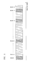
- FIG. 1 illustrates an example of the quarter rate qLS-4 where the total number of subcarriers to be used is 64.
- all the subcarriers are segmentalized into 64/4 regions, i.e., 16 regions each including 4 subcarriers.
- Subcarriers included in the hatched regions 1, 6, 12, and 15 are used.
- Each region includes 4 subcarriers, and therefore 16 subcarriers are used in this example.
- An average SINR and the PAPR characteristics differ according to the number of segmentalizations and the number of frequency domain signals included in each segment.
- the SINR As the number of segmentalizations increases, i.e., as the number of frequency domain signals included in each segment decreases, the SINR further improves, and the PAPR characteristics further degrades. In other words, the SINR and the PAPR characteristics are in a trade-off relationship.
- a degradation of the PAPR characteristics indicates a high possibility of an instantaneously-high power being output with respect to the average power.
- FIG. 2A is a schematic block diagram illustrating a configuration of the mobile terminal device (wireless transmission device) 20 that uses DFT-s-OFDM and can change a first modulation scheme, the number of subcarriers to be used, and the number of frequency domain signals included in each segment.
- the mobile terminal device 20 includes an encoder 1, a digital modulator 2, an S/P converter 3, a DFT unit 4, a segmentalizing unit 5, a subcarrier allocating unit 6, an IDFT unit 7, a GI inserter 8, a P/S converter 8, a power controller 10, a D/A converter 11, an RF unit 12, a controller 13, and a receiver 14.
- the encoder 1 performs encoding, such as error correction coding, on input transmission data.
- the digital modulator 2 performs on the encoded transmission data, a first modulation, such as BPSK or QPSK (Quadrature Phase Shift Keying).
- the S/P (Serial/Parallel) converter 3 performs serial/parallel conversion to input to the DFT unit 4, time domain signals having been subjected to encoding, modulation, and the like.
- the DFT unit (time-frequency converter) 4 performs DFT on the time domain signals having been subjected to the serial/parallel conversion to generate frequency domain signals.
- the segmentalizing unit 5 segmentalizes the frequency domain signals output from the DFT unit 4 for each specified number of frequency domain signals.
- the subcarrier allocating unit 6 allocates the segmentalized frequency domain signals to subcarriers to be transmitted.
- the IDFT unit (frequency-time converter) 7 performs IDFT on the frequency domain signals allocated to the subcarriers.
- the GI inserter 8 inserts a guard interval (GI) defined by the system into an output of the IDFT unit 7.
- the P/S converter 9 performs parallel/serial conversion on the output of the GI inserter 8.
- the power controller 10 controls the power of the signal output from the P/S converter 9.
- the digital/analog (D/A) converter 11 converts the output of the power controller 10, which is a digital signal, into an analog signal. It is assumed that the total power is not changed before and after the spatial conversion is performed by the IDFT unit 7 and the DFT unit 4.
- the controller 13 performs adaptive control on the digital modulator 2, the S/P converter 3, the DFT unit 4, the segmentalizing unit 5, the subcarrier allocating unit 6, and the power controller 10.
- the receiver 14 receives data transmitted from the base station device 30 and control information, such as channel quality. Additionally, the receiver 14 outputs the received data, and inputs the control information to the controller 13.
- the mobile terminal device 20 of the present embodiment shown in FIG. 2 performs transmission using a known scheme called DFT-s-OFDM (see 3GPP R1-050702 "DFT-Spread OFDM with Pulse Shaping Filter in Frequency Domain in Evolved UTRA Uplink").
- the mobile terminal device 20 may perform transmission using another spectrum control single carrier scheme, such as a single carrier CI in which different phase rotations are added to respective time domain signals to generate frequency domain signals instead of the DFT unit 2 performing Fourier transform to generate frequency domain signals (see The 17th Annual IEEE International Symposium on Personal, Indoor and Mobile Radio Communications (PIMRC '06) "MICROSCOPIC SPECTRUM CONTROL TECHNIQUE USING CARRIER INTERFEROMETRY FOR ONE CELL REUSE SINGLE CARRIER TDMA SYSTEMS").
- PIMRC '06 "MICROSCOPIC SPECTRUM CONTROL TECHNIQUE USING CARRIER INTERFEROMETRY FOR ONE CELL REUSE SINGLE CARRIER TDMA SYSTEMS"
- Control information A output from the controller 13 is information for specifying a first modulation scheme to the digital modulator 2.
- Control information B output from the controller 13 is information for specifying the number of subcarriers to be used in the S/P converter 3 and the DFT unit 4.
- Control information C output from the controller 13 is information for specifying the number of frequency domain signals included in each segment to the segmentalizing unit 5.
- Control information D output from the controller 13 is information for specifying to the subcarrier allocating unit 6, subcarriers to be used which are specified by the base station device 30 or the like.
- the control information E output from the controller 13 is information for the power controller 10 to control the transmission power.
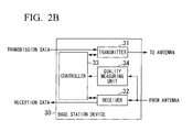
- FIG. 2B is a schematic block diagram illustrating a configuration of the base station device 30 communicating with the mobile terminal device 20.
- the base station device 30 includes a transmitter 31, a receiver 32, a controller 33, and a quality measuring unit 34.
- the transmitter 31 transmits input transmission data, and control data received from the controller 33 to the mobile terminal device 20 through an antenna.
- the receiver 32 receives reception data received from the mobile terminal device 20 through the antenna and the control data. Then, the receiver 32 outputs the reception data, and outputs the control data to the controller 33.
- the controller 33 performs uplink and downlink scheduling based on the control data received from the receiver 32. Additionally, the controller 33 orders the transmitter 31 to transmit an SINR of each mobile terminal device 20, which is received from the quality measuring unit 34, to the corresponding mobile terminal device 20.
- the quality measuring unit 34 measures an SINR of each subcarrier for each mobile terminal device 20, and outputs the results to the controller 33.
- a first embodiment explains the adaptive control achieved by changing the number of frequency domain signals included in each segment.
- the control information A indicates one of BPSK and QPSK
- the control information B indicates 32 subcarriers that do not change (the total number of subcarriers to be used is 64).
- the control information D i.e., subcarrier allocation is suitably selected based on the number of frequency domain signals included in each segment, as will be explained later.
- the base station device 30 which is the transmission destination of the mobile station device 20, informs the mobile station device 20 of an SINR of each subcarrier.
- the base station device 30 may determine subcarriers to be used and inform the mobile station device 20 of the determined subcarriers.
- the controller 13 selects a combination of sub carriers achieving the best SINR for each of the numbers of frequency domain signals included in each segment 32, 16, 8, and 1.
- the average SINR of the selected subcarriers is defined as hLS-xxbest, such as hLS-32best, hLS-16best, hLS-8best, or hLS-1best.
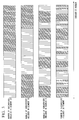
- FIG 3 illustrates an example of combinations of subcarriers achieving the best average SINR for each of the numbers of frequency domain signals included in each segment.
- the horizontal axis denotes the subcarrier numbers from subcarrier 1 to subcarrier 64. When the number of frequency domain signals included in each segment is 8 in the case of the half rate, 32 subcarriers are used, and then the number of segments is 4.
- the first segment includes subcarriers 1 to 8.
- the second segment includes subcarriers 21 to 28.
- the third segment includes subcarriers 41 to 48.
- the fourth segment includes subcarriers 53 to 60.
- the controller 13 calculates hLS-xxbest for each selected combination.
- the hatched subcarriers shown in FIG. 3 indicate selected subcarriers.
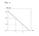
- FIG. 3 illustrates an example of the QPSK error rate characteristics for a channel. The horizontal and vertical axes shown in FIG.
- SINR SINR and a bit error rate, respectively.
- CQ-tqpsk becomes Y1 (dB).
- CQ-tqpsk becomes Y2 (dB).
- the controller 13 compares each hLS-xxbest to Y1 and Y2, and selects hLS-xxbest.
- the controller 13 calculates the error rate characteristics with respect to the SINR as shown in FIG 4 based on channel interference. However, the error rate characteristics with respect to a logically calculated SNR (the error rate characteristics when only white noise is present with no channel variation) may be used. If multiple hLS-xxbest are present, hLS-xxbest whose value of xx is larger, i.e., whose value of a PAPR is stochastically smaller, is selected.
- the controller 13 compares hLS-xxbest to target CQ-tbpsk when the first modulation scheme is BPSK. Then, the controller 13 selects hLS-xxbest that can achieve an SINR exceeding CQ-tbpsk in a similar manner. If multiple hLS-xxbest are present, hLS-xxbest whose value of xx is larger, i.e., whose value of a PAPR is stochastically smaller, is selected.
- the controller 13 selects the value of xx indicative of the number of frequency domain signals included in each segment, and selects the first modulation scheme at the same time. For example, if hLS-8best is selected with respect to CQ-tqpsk, the controller 13 outputs control information A indicating that BPSK is to be selected, and control information C indicating that the number of frequency domain signals included in each segment is 8.
- control information A indicating that BPSK is to be selected
- control information C indicating that the number of frequency domain signals included in each segment is 8.
- an instantaneously-high power can be stochastically prevented. Therefore, when an instantaneous power becomes larger depending on data, and signal elements degrade due to nonlinear distortion upon power amplification, an instantaneous degradation of a communication quality (i.e., an error occurs depending on transmission data) can be prevented. Additionally, the effect of signals intruding into out-of-band communication and affecting another communication system can be prevented. It is assumed in the first embodiment that multiple mobile terminal devices 20 simultaneously access the base station device 30 using FDM (Frequency Division Multiplex). Therefore, the effect on out-of-band communications, i.e., the effect on a transmission band of another mobile terminal device 20 can be prevented.
- FDM Frequency Division Multiplex
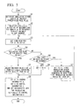
- FIG 5 is a flowchart for the controller 13 to determine a first modulation scheme and the number of frequency domain signals included in each segment.
- the controller 13 initiates the first modulation.
- the controller 13 selects a modulation scheme achieving the maximum transmission rate in the system and sets the modulation scheme to a parameter ml (S1).
- QPSK is set to ml.
- the controller 13 selects for each value of xx that is the number of frequency domain signals included in each segment, a subcarrier group achieving the maximum SINR.
- the controller 13 substitutes an average SINR for all the subcarriers to be used into LS-xxbest (S2).
- the controller 13 sets to the parameter CQ-tml, an SINR required for using the modulation scheme set to the parameter ml.
- the parameter CQ-tml is determined based on a required communication quality, which is SINR in the first embodiment. Then, the controller 13 determines whether or not hLS-xxbest achieving an SINR exceeding the parameter CQ-tml is present among multiple pieces of hLS-xxbest (S4). If the controller 13 determines that hLS-xxbest achieving an SINR exceeding the parameter CQ-tml is present, the controller 13 selects from pieces of hLS-xxbest achieving better quality than the parameter CQ-tml, one having the largest value of xx that is the number of frequency domain signals included in each segment. Then, the controller 13 sets the value of the number xx of frequency domain signals included in each segment to the parameter X (S5).
- the controller 13 determines each control information piece.
- the controller 13 sets the parameter ml indicative of the first modulation scheme to the control information A.
- the controller 13 sets to the control information C, the parameter X indicative of the number of frequency domain signals included in each segment.
- the controller 13 sets to the control information D, information indicative of the subcarriers selected for calculating hLS-xxbest when the parameter X is the number of frequency domain signals included in each segment.
- the controller 13 determines based on the setting of the parameter ml whether or not the first modulation scheme can be changed.
- the controller 13 determines that the first modulation scheme can be changed. If a first modulation scheme having not been set is not present in steps S1 and S7, the controller 13 determines that the first modulation scheme cannot be changed.
- step S6 determines in step S6 that the first modulation scheme can be changed
- the controller 13 sets to the parameter ml, a first modulation scheme achieving the maximum transmission rate among first modulation schemes having not been set in steps S 1 and S7, and then returns to step S3 (S7).
- step S6 determines in step S6 that the first modulation scheme cannot be changed
- 1 is set to the parameter X in this case and communication using LS-1 at the full rate is performed in which the first modulation scheme achieving the maximum resistance against noise and interference, and subcarriers achieving better qualities can be selected, and the number of frequency domain signals included in each segment is 1.
- some restriction may be made based on a condition of the mobile terminal device 20, for example, the remaining amount of power supply or a required transmission power.
- the remaining amount of power supply is small or when high transmission power is required, if a signal having a large instantaneous power is input to an amplifier, an output thereof has a high possibility of being distorted.
- a restriction such that 1 is not set to the number of frequency domain signals included in each segment, i.e., LS-1 is not used, may be made, and thereby the communication quality can be improved.
- the control information shown in FIG. 2 may be determined by the base station device 30. Even when the control information is determined by the controller 33 of the base station device 30, the same flowchart shown in FIG. 5 can be used for the determination process.
- the base station device 30 informs the mobile terminal device 20 of the determined control information through the downlink.
- the receiver 14 of the mobile terminal device 20 receives the information, and the controller 13 sets the value indicated by the received information to each control information piece.
- a mobile terminal device and a base station device that are used in a second embodiment are the same as ones explained in the first embodiment with reference to FIGS. 2A and 2B except for the following.
- the control information pieces C and D which are output from the controller of the mobile terminal device, differ. Consequently, the configuration of the controller 13 is changed with this respect.
- the same can apply to the base station device.
- the second embodiment explains a different method from that of the first embodiment where parameters shown in Table 1 are selected. Therefore, the total number of subcarriers to be used can be selected from 64 (full), 32 (half), and 16 (quarter).
- a first modulation scheme can be selected from 16QAM, QPSK, and BPSK.
- the number of frequency domain signals included in each segment can be selected from the types shown in Table 1, i.e., from LS-1, LS-8, LS-16, LS-32, and LS-64.
- An isolated cell (which is less affected by interference) is assumed in the second embodiment. In this case, noise is the primary factor of SINRs.
- a predetermined target communication quality is Err-t, it is assumed that average SINRs required for the respective first modulation schemes are CQ-tbpsk, CQ-tqpsk, and CQ-t16qam.
- the maximum average SINR with respect to each of the numbers of frequency domain signals included in each segment is calculated.
- the average SINR is uniquely determined, which is defined as LS-64best.
- the maximum average SINR differs depending on the number of frequency domain signals included in each segment, which are defined as hLS-32best, hLS-16best, hLS-8best, and hLS-1best.
- the determined average SINRs are defined as hLS-16best, hLS-8best, and hLS-1best. Similar to the first embodiment, the controller 13 of the mobile terminal device 20 or the base station device 30 selects parameters as explained hereinafter.
- SINR required for achieving a target communication quality for each first communication scheme (hereinafter, “desired SINR") and the SINR calculated for each of the numbers of frequency domain signals included in each segment are compared to select combinations of modulation schemes achieving SINRs exceeding the desired SINR.
- Table 2 illustrates an example of the selection results. In Table 2, the combinations crossed out with two lines are combinations of modulation schemes that cannot satisfy the desired SINR. In Table 2 and other Tables shown later, "best" of hLS-xxbest is omitted.
- the full-QPSK LS-64 and the half 16QAM hLS-1 are the candidates in the case of Table 2. If multiple candidates are included in the selected region, one of hLS-xx and qLS-xx, which has the largest value of xx, is selected. This is because the PAPR characteristics are better as a value of xx is larger. Since only one candidate is included in the selected region shown in Table 2, this operation is not necessary. Although any one of the hLS-xx or qLS-xx has to be selected, it is not necessary to consider effects on another system in the case of an isolated cell. In such a case, an optimal parameter is selected based on the determination criteria of each terminal.
- a first modulation scheme using the smaller number of signals is selected (i.e., QPSK (2 bits) is selected rather than 16QAM (4 bits), and BPSK (1 bit) is selected rather than QPSK).
- QPSK is set to the control information A (first modulation scheme) shown in FIG. 2 .
- 64 is set to the control information B (the number of subcarriers).
- 64 is set to the control information C (the number of frequency domain signals included in each segment).
- the subcarriers used for setting LS-64best are set to the control information D (subcarriers).
- a method of selecting parameters in consideration of the PAPR characteristics can be considered. In this case, when the total number of subcarriers to be used is small, it has to be considered that the total transmission power (i.e., average power) becomes small.
- the target communication quality is satisfied, and the transmission rate can be maximized, thereby minimizing a degradation of the PAPR characteristics.
- a mobile terminal device and a base station device that are used in a third embodiment are the same as those explained in the first embodiment with reference to FIGS. 2A and 2B except for the following.
- the control information pieces C and D which are output from the controller of the mobile terminal device, differ. Consequently, the configuration of the controller 13 is changed in this respect.
- the same can apply to the base station device.
- the third embodiment explains a case where DFT-s-OFDM, in which adaptive control is performed, is used for a single frequency reuse cellular system.
- the single frequency reuse cellular system is a system in which the same frequency band is used by every cell, and therefore high frequency utilization efficiency can be achieved, but the effects of interference signals from neighboring cells are problematic.
- interferences are primary factors of SINRs in the system.
- parameters to be used here are the same as those shown in the second embodiment. Similar to the first and second embodiments, the controller 13 of the mobile terminal device 20 or the base station device 30 selects parameters as will be explained hereinafter.
- a desired SINR for each first modulation scheme and the SINR calculated for each of the numbers of frequency domain signals included in each segment are compared to select combinations of modulation schemes achieving SINRs exceeding the desired SINR.
- Table 3 illustrates an example of the selection results. In Table 3, the combinations crossed out with two lines are combinations that cannot satisfy the desired SINR.
- a combination achieving the maximum transmission rate is selected from the combinations remaining as candidates shown in Table 3, the communication quality Err-t is satisfied, and the largest amount of data can be transmitted in a unit of time, thereby improving the communication efficiency.
- 5 combinations of the full-BPSK LS-64, the half-QPSK hLS-1 to 16, and the quarter-16QAM qLS-1 are the candidates.
- a parameter achieving less transmission power per bit i.e. a parameter achieving the smaller number of subcarriers, is preferably selected in consideration of the effects on other cells.
- the quarter-16QAM qLS-1 is selected consequently. This is because the transmission rate is prioritized, and next the smaller number of subcarriers to be used is prioritized, thereby improving the communication efficiency of the entire system.
- 16QAM is set to the control information A (first modulation scheme) shown in FIG. 2 . 16 is set to the control information B (the number of subcarriers). 1 is set to the control information C (the number of frequency domain signals included in each segment). The subcarriers used for setting qLS-1best are set to the control information D (subcarriers).
- the number of subcarriers to be used in each cell is controlled to be small, resulting in a lower inter-cell interference.
- the transmission rate can be maximized while the target communication quality is satisfied. Further, interference with other cells can be reduced. Moreover, a degradation of the PAPR characteristics can be minimized.
- the isolated cell and the cell affected by interference are assumed in the second and third embodiments, respectively.
- the interference power within the communication band is estimated.
- the estimated interference power is compared to a predetermined threshold. Thus, whether the dependency of SINR on the interference power is high or low may be determined.
- the parameter selecting method of the second embodiment and the parameter selecting method of the third embodiment may be adaptively switched.
- a mobile terminal device and a base station device that are used in a fourth embodiment are the same as those explained in the first embodiment with reference to FIGS. 2A and 2B except for the following.
- the control information pieces C and D which are output from the controller of the mobile terminal device, differ. Consequently, the configuration of the controller 13 is changed in this respect.
- the same can apply to the base station device.
- the second and third embodiments have explained the case where the transmission power is not controlled with respect to the parameter to be selected. In this case, the total transmission power in the case of the half rate and the quarter rate is smaller than in the case of the full rate.
- the fourth embodiment explains the case where the transmission power is controlled to be constant. Similar to the first to third embodiments, the controller 13 of the mobile terminal device 20 or the base station device 30 selects parameters as explained later.
- the power control is performed based on the control information E shown in FIG. 2 . If the half rate is selected, the signal power is controlled to be double the signal power in the case of the full rate. If the quarter rate is selected, the signal power is controlled to be four times the signal power in the case of the full rate.
- a desired SINR for each first modulation scheme and the SINR calculated for each of the numbers of frequency domain signals included in each segment are compared to select combinations of modulation schemes achieving SINR exceeding the desired SINR.
- Table 4 illustrates an example of the selection results.
- the transmission power is controlled in the fourth embodiment. Therefore, if the transmission rate is the same, the transmission signal power per bit is the same. Candidates in regions corresponding to the same transmission rate are likely to remain as the final selection candidates.
- Table 4 illustrates candidates of parameters selected based on signal quality. In Table 4, the combinations crossed out with two lines are combinations that cannot satisfy the desired SINR.
- a parameter is selected from these candidates shown in Table 4 based on a condition of the mobile terminal device 20.
- a combination achieving the largest number of frequency domain signals included in each segment is selected in consideration of only the PAPR characteristics. Consequently, the full-BPSK LS-64 is preferably selected.
- the quarter 16QAM achieving the smallest number of subcarriers to be used is preferably selected in consideration of the effects on other cells.
- qLS-16best achieving the better PAPR characteristics is selected since an amplifier for amplifying the transmission power is required to be used as efficiently as possible. Consequently, the qLS-16best achieving the better PAPR characteristics is selected.
- the mobile terminal device 20 having the small remaining amount of power supply may delete a combination causing poor PAPR characteristics from the selection candidates.
- hLS-1, hLS-8, qLS-1, and qLS-8 are deleted from the candidates. Consequently, one of the full-BPSK LS-64best, the half-QPSK hLS-16best, the half-QPSK hLS-32best, and the quarter-16QAM qLS-16best is selected.
- FIG. 6 is a flowchart of adaptively switching the operations of the second and third embodiments according to the fourth embodiment.
- the second and third embodiments can be implemented by using a part of this flowchart.
- the controller 13 selects subcarriers achieving the best average SINR for each combination of a first modulation scheme and the number of frequency domain signals included in each segment. Then, the controller 13 sets the average SINR of the selected subcarriers to LS-xx, hLS-xx, and qLS-xx (S21). Then, the controller 13 determines whether or not the mobile terminal device 20 is dependent on terminal characteristics (S22).
- the controller 13 determines whether or not the mobile terminal device 20 tolerates the PAPR characteristics in consideration of several factors of each mobile terminal device 20, such as the aforementioned remaining amount of power supply, or the utilization efficiency of an amplifier for amplifying the transmission power. For example, if the remaining mount of power supply is small, and if the amount of power that can be supplied is smaller than a predetermined threshold, it is determined that the mobile terminal device 20 does not tolerate the PAPR characteristics. Alternatively, if the transmission power is greater than a predetermined threshold and exceeds a linear region of the amplifier at a peak, it is determined that the mobile terminal device 20 does not tolerate the PAPR characteristics. If the mobile terminal device 20 does not tolerate the PAPR characteristics, it is determined that the mobile terminal device 20 is dependent on the terminal characteristics.
- step S22 If it is determined in step S22 that the mobile terminal device 20 is likely to be affected by a degradation of the PAPR characteristics, i.e., if it is determined that the mobile terminal device 20 is dependent on the terminal characteristics, the controller 13 preliminarily deletes from the combinations of parameters, LS-1, hLS-1, and qLS-1 causing the poor PAPR characteristics (S23). It is assumed here that the combination satisfying a condition that the number of frequency domain signals included in each segment is 1 is deleted. However, combinations satisfying a condition that the number of frequency domain signals included in each segment is equal to or smaller than a predetermined threshold, such as 2 or less, 4 or less, or the like, may be deleted.
- a predetermined threshold such as 2 or less, 4 or less, or the like
- step S23 the controller 13 sets CQ-tml, which is the average SINR satisfying the desired communication quality required for each first modulation scheme (S25).
- the CQ-tml differs depending on a first modulation scheme.
- the controller 13 deletes a candidate not satisfying CQ-tml (S26).
- the operation of step S26 corresponds to the operation of crossing out with two lines candidates shown in Tables 2 and 3 shown in the second and third embodiments.
- the controller 13 selects a region achieving the maximum transmission rate from regions corresponding to the modulation scheme satisfying the set desired quality (S27). At this time, multiple regions might be selected.
- the regions indicate the regions A to I shown in Table. Multiple candidates may be included in the selected region correspondingly to the number of frequency domain signals included in each segment.
- the controller 13 determines whether or not the region selected in step S27 is present (S28). If it is determined that the selected region is not present, the controller 13 proceeds to the step S30, selects a region achieving the lowest transmission rate from among all the regions, and proceeds to step S33. On the other hand, if it is determined that the region selected in step S28 is present, the controller 13 determines whether or not the communication environment of the mobile terminal device 20 is interference-dependent (S29). This determination is performed based on whether or not the absolute amount of interference power is equal to or greater than a threshold. Alternatively, whether or not an isolated cell or interference cell is present may be determined in step S29. If it is determined in step S29 that the communication environment is interference-dependent, the controller 13 selects a region achieving the smallest number ofsubcarriers to be used from the regions selected in step S27 (S31), and then proceeds to step S33.
- S29 the communication environment of the mobile terminal device 20 is interference-dependent
- step S29 If it is determined in step S29 that the communication environment is not interference-dependent, the controller 13 selects a region achieving the smaller number of modulation levels of the first modulation scheme from the regions selected in step S27 (S32), and then proceeds to step S33.
- This branching corresponds to the second embodiment.
- the controller 13 selects in step S33, a region achieving the largest number of frequency domain signals included in each segment from the regions selected in any one of steps S30, S31, and S32. Further, the controller 13 performs power control based on the rate of the selected region, and thus the flowchart ends.
- step S28 the controller 13 proceeds to step S29. Since the controller 13 determines in step S29 that the communication environment is highly interference-dependent, the controller 13 selects the region G in step S31. This branching corresponds to the third embodiment. Then, the controller 13 selects LS16 in step S33. Consequently, 16QAM is set to the control information A, 16 is set to the control information B, 16 is set to the control information C, and the subcarriers used for calculation in step S21 are allocated to the control information D.
- Such controls enable maximization of the transmission rate and minimization of a degradation of the PAPR characteristics in consideration of dependency on the terminal characteristics and interference with other cells.
- Programs for implementing the functions of the encoder 1, the digital modulator 2, the S/P converter 3, the DFT unit 3, the segmentalizing unit 5, the subcarrier allocating unit 6, the IDFT unit 7, the GI inserter 8, the P/S converter 9, the power controller 10, and the controller 13, which are shown in FIG. 2 may be stored in a computer-readable recording medium, and thereby operations of the respective units may be performed by a computer system reading the programs.
- the "computer system” described here includes OS and hardware, such as peripheral devices.
- the "computer-readable recording medium” includes a portable medium, such as a flexible disk, an optical disc, an ROM, a CD-ROM, and the like, and a storage device such as a hard disk installed in a computer system.
- the "computer-readable recording medium” includes a medium dynamically storing a program for a short period, such as a communication line when a program is transmitted through a network such as the Internet or a communication line such as a telephone line.
- the "computer-readable recording medium” includes a medium storing a program for a given period, such as a volatile memory in a computer system of a server or a client in the above case.
- the program may be one for implementing a part of the aforementioned functions or one for implementing the aforementioned functions by combining another program stored in the computer system.
- the present invention is suitable, but is not limited to a mobile communication system using a spectrum control single carrier communication scheme in an uplink.
Landscapes
- Engineering & Computer Science (AREA)
- Signal Processing (AREA)
- Computer Networks & Wireless Communication (AREA)
- Quality & Reliability (AREA)
- Mobile Radio Communication Systems (AREA)
- Transmitters (AREA)
- Digital Transmission Methods That Use Modulated Carrier Waves (AREA)
Applications Claiming Priority (2)
| Application Number | Priority Date | Filing Date | Title |
|---|---|---|---|
| JP2007304321 | 2007-11-26 | ||
| PCT/JP2008/071401 WO2009069630A1 (fr) | 2007-11-26 | 2008-11-26 | Système de radio communication, dispositif d'émission radio, procédé de radio communication et programme |
Publications (2)
| Publication Number | Publication Date |
|---|---|
| EP2216924A1 true EP2216924A1 (fr) | 2010-08-11 |
| EP2216924A4 EP2216924A4 (fr) | 2014-08-13 |
Family
ID=40678525
Family Applications (1)
| Application Number | Title | Priority Date | Filing Date |
|---|---|---|---|
| EP08854308.7A Withdrawn EP2216924A4 (fr) | 2007-11-26 | 2008-11-26 | Système de radio communication, dispositif d'émission radio, procédé de radio communication et programme |
Country Status (7)
| Country | Link |
|---|---|
| US (1) | US8411770B2 (fr) |
| EP (1) | EP2216924A4 (fr) |
| JP (2) | JPWO2009069630A1 (fr) |
| CN (1) | CN101874370B (fr) |
| AU (1) | AU2008330673B2 (fr) |
| EA (1) | EA018288B1 (fr) |
| WO (1) | WO2009069630A1 (fr) |
Families Citing this family (33)
| Publication number | Priority date | Publication date | Assignee | Title |
|---|---|---|---|---|
| US5955992A (en) * | 1998-02-12 | 1999-09-21 | Shattil; Steve J. | Frequency-shifted feedback cavity used as a phased array antenna controller and carrier interference multiple access spread-spectrum transmitter |
| US8670390B2 (en) | 2000-11-22 | 2014-03-11 | Genghiscomm Holdings, LLC | Cooperative beam-forming in wireless networks |
| US9819449B2 (en) | 2002-05-14 | 2017-11-14 | Genghiscomm Holdings, LLC | Cooperative subspace demultiplexing in content delivery networks |
| US10355720B2 (en) | 2001-04-26 | 2019-07-16 | Genghiscomm Holdings, LLC | Distributed software-defined radio |
| US10425135B2 (en) | 2001-04-26 | 2019-09-24 | Genghiscomm Holdings, LLC | Coordinated multipoint systems |
| US9893774B2 (en) | 2001-04-26 | 2018-02-13 | Genghiscomm Holdings, LLC | Cloud radio access network |
| US10931338B2 (en) | 2001-04-26 | 2021-02-23 | Genghiscomm Holdings, LLC | Coordinated multipoint systems |
| US10644916B1 (en) | 2002-05-14 | 2020-05-05 | Genghiscomm Holdings, LLC | Spreading and precoding in OFDM |
| US10200227B2 (en) | 2002-05-14 | 2019-02-05 | Genghiscomm Holdings, LLC | Pre-coding in multi-user MIMO |
| US9628231B2 (en) | 2002-05-14 | 2017-04-18 | Genghiscomm Holdings, LLC | Spreading and precoding in OFDM |
| US10142082B1 (en) | 2002-05-14 | 2018-11-27 | Genghiscomm Holdings, LLC | Pre-coding in OFDM |
| US11184037B1 (en) | 2004-08-02 | 2021-11-23 | Genghiscomm Holdings, LLC | Demodulating and decoding carrier interferometry signals |
| US11431386B1 (en) | 2004-08-02 | 2022-08-30 | Genghiscomm Holdings, LLC | Transmit pre-coding |
| US11552737B1 (en) | 2004-08-02 | 2023-01-10 | Genghiscomm Holdings, LLC | Cooperative MIMO |
| WO2008081876A1 (fr) * | 2006-12-28 | 2008-07-10 | Sharp Kabushiki Kaisha | Dispositif de transmission radio, dispositif de commande, système de communication radio et procédé de communication |
| RU2010151976A (ru) * | 2008-06-20 | 2012-06-27 | Панасоник Корпорэйшн (Jp) | Устройство беспроводной передачи и способ беспроводной передачи |
| CN104660534B (zh) * | 2008-09-18 | 2018-02-09 | 三菱电机株式会社 | 发送装置以及接收装置 |
| WO2010061248A1 (fr) * | 2008-11-28 | 2010-06-03 | Freescale Semiconductor, Inc. | Allocation de canaux de communication |
| JP2011124779A (ja) * | 2009-12-10 | 2011-06-23 | Nec Corp | 無線通信システム、無線通信装置、及び無線通信方法 |
| US9363769B2 (en) * | 2010-05-05 | 2016-06-07 | Qualcomm Incorporated | Methods and systems for SRS power scaling in carrier aggregation |
| WO2015022034A1 (fr) * | 2013-08-16 | 2015-02-19 | Telefonaktiebolaget L M Ericsson (Publ) | Procédé et appareil de syntonisation de supercanal |
| US9148182B2 (en) * | 2013-10-09 | 2015-09-29 | Maxlinear, Inc. | Power combining power amplifier architectures and methods |
| US12224860B1 (en) | 2014-01-30 | 2025-02-11 | Genghiscomm Holdings, LLC | Linear coding in decentralized networks |
| EP3082287A1 (fr) * | 2015-04-16 | 2016-10-19 | Gemalto M2M GmbH | Procédé de communication en liaison montante dans un réseau cellulaire lte |
| US10917167B2 (en) * | 2015-05-29 | 2021-02-09 | Huawei Technologies Co., Ltd. | MC-CDMA with low peak-to-average power ratio multi-carrier waveform |
| US10158458B2 (en) | 2015-05-29 | 2018-12-18 | Huawei Technologies Co., Ltd. | Systems and methods for partial collision multiple access |
| WO2018031952A1 (fr) * | 2016-08-12 | 2018-02-15 | Cohere Technologies | Égalisation et décodage itératifs multiniveaux |
| US10637705B1 (en) | 2017-05-25 | 2020-04-28 | Genghiscomm Holdings, LLC | Peak-to-average-power reduction for OFDM multiple access |
| US10243773B1 (en) | 2017-06-30 | 2019-03-26 | Genghiscomm Holdings, LLC | Efficient peak-to-average-power reduction for OFDM and MIMO-OFDM |
| US12206535B1 (en) | 2018-06-17 | 2025-01-21 | Tybalt, Llc | Artificial neural networks in wireless communication systems |
| US11343823B2 (en) | 2020-08-16 | 2022-05-24 | Tybalt, Llc | Orthogonal multiple access and non-orthogonal multiple access |
| EP3915236A4 (fr) | 2019-01-25 | 2023-05-24 | Genghiscomm Holdings, LLC | Accès multiple orthogonal, et accès multiple non orthogonal |
| WO2020242898A1 (fr) | 2019-05-26 | 2020-12-03 | Genghiscomm Holdings, LLC | Accès multiple non orthogonal |
Family Cites Families (25)
| Publication number | Priority date | Publication date | Assignee | Title |
|---|---|---|---|---|
| SU1585902A1 (ru) * | 1988-05-11 | 1990-08-15 | Серпуховское высшее военное командно-инженерное училище ракетных войск им.Ленинского комсомола | Многопараметрическа адаптивна система радиосв зи дл передачи дискретной информации |
| JP3107528B2 (ja) * | 1997-08-07 | 2000-11-13 | 日本電信電話株式会社 | 誤り補償方法およびマルチキャリア伝送装置 |
| UA30803A (uk) * | 1998-06-04 | 2000-12-15 | Державне Підприємство "Кб Оризон-Навігація" | Спосіб і пристрій широкосмугового багатоканального адресного дуплексного радіозв'язку |
| US6493331B1 (en) * | 2000-03-30 | 2002-12-10 | Qualcomm Incorporated | Method and apparatus for controlling transmissions of a communications systems |
| JP2003283460A (ja) * | 2002-03-26 | 2003-10-03 | Matsushita Electric Ind Co Ltd | マルチキャリア送信装置およびマルチキャリア送信方法 |
| JP4115784B2 (ja) * | 2002-09-11 | 2008-07-09 | 三菱電機株式会社 | 再送制御方法および通信装置 |
| US8422434B2 (en) * | 2003-02-18 | 2013-04-16 | Qualcomm Incorporated | Peak-to-average power ratio management for multi-carrier modulation in wireless communication systems |
| EP3484089B1 (fr) * | 2003-08-20 | 2021-11-24 | Panasonic Corporation | Appareil de communication sans fil et procédé d'attribution de sous-porteuses |
| RU2408986C2 (ru) * | 2003-08-20 | 2011-01-10 | Панасоник Корпорэйшн | Устройство беспроводной связи и способ выделения поднесущих |
| RU2267863C2 (ru) * | 2003-08-21 | 2006-01-10 | Корпорация "Самсунг Электроникс" | Способ адаптивного распределения частотно-временного ресурса, адаптивной модуляции, кодирования и регулировки мощности в системе связи |
| JP4358271B2 (ja) * | 2004-03-05 | 2009-11-04 | サムスン エレクトロニクス カンパニー リミテッド | 多重搬送波を用いる広帯域無線通信システムにおける副搬送波割り当て方法及び装置 |
| US7706350B2 (en) * | 2004-03-19 | 2010-04-27 | Qualcomm Incorporated | Methods and apparatus for flexible spectrum allocation in communication systems |
| CN1691659B (zh) * | 2004-04-23 | 2012-01-18 | 北京三星通信技术研究有限公司 | 在正交频分复用系统中用于同步的方法 |
| US20050249127A1 (en) * | 2004-05-10 | 2005-11-10 | Lucent Technologies, Inc. | Method for subcarrier allocation |
| JP4511906B2 (ja) * | 2004-11-02 | 2010-07-28 | パナソニック株式会社 | 送信装置及び送信方法 |
| WO2007000923A1 (fr) * | 2005-06-27 | 2007-01-04 | Matsushita Electric Industrial Co., Ltd. | Appareil de transmission multiporteuse et méthode de transmission multiporteuse |
| US9209956B2 (en) * | 2005-08-22 | 2015-12-08 | Qualcomm Incorporated | Segment sensitive scheduling |
| US8218563B2 (en) * | 2005-11-04 | 2012-07-10 | Samsung Electronics Co., Ltd. | Method and system for providing adaptive modulation and coding in a multi-carrier wireless network |
| KR100866981B1 (ko) * | 2006-01-13 | 2008-11-05 | 한국전자통신연구원 | 직교 주파수 분할 다중화 심볼을 생성하고 수신하는 장치및 방법 |
| RU2455789C2 (ru) * | 2006-01-18 | 2012-07-10 | Телефонактиеболагет Л М Эрикссон (Пабл) | Локализованная и распределенная передача |
| EP1990942A1 (fr) * | 2006-03-20 | 2008-11-12 | Matsushita Electric Industrial Co., Ltd. | Système de radiocommunication, dispositif de radiotransmission et procédé de retransmission |
| CN101043485A (zh) * | 2006-03-22 | 2007-09-26 | 松下电器产业株式会社 | 发送方法、接收方法和设备及通信系统 |
| JP4946159B2 (ja) * | 2006-05-09 | 2012-06-06 | 富士通株式会社 | 無線送信方法及び無線受信方法並びに無線送信装置及び無線受信装置 |
| WO2008081876A1 (fr) | 2006-12-28 | 2008-07-10 | Sharp Kabushiki Kaisha | Dispositif de transmission radio, dispositif de commande, système de communication radio et procédé de communication |
| US8571126B2 (en) * | 2007-05-15 | 2013-10-29 | Rambus Inc. | Multi-antenna transmitter for multi-tone signaling |
-
2008
- 2008-11-26 CN CN200880117468.1A patent/CN101874370B/zh not_active Ceased
- 2008-11-26 EA EA201070624A patent/EA018288B1/ru not_active IP Right Cessation
- 2008-11-26 US US12/744,639 patent/US8411770B2/en active Active
- 2008-11-26 JP JP2009543816A patent/JPWO2009069630A1/ja active Pending
- 2008-11-26 WO PCT/JP2008/071401 patent/WO2009069630A1/fr not_active Ceased
- 2008-11-26 AU AU2008330673A patent/AU2008330673B2/en not_active Ceased
- 2008-11-26 EP EP08854308.7A patent/EP2216924A4/fr not_active Withdrawn
-
2014
- 2014-04-23 JP JP2014088749A patent/JP2014140256A/ja active Pending
Also Published As
| Publication number | Publication date |
|---|---|
| CN101874370A (zh) | 2010-10-27 |
| AU2008330673A1 (en) | 2009-06-04 |
| WO2009069630A1 (fr) | 2009-06-04 |
| US20100254484A1 (en) | 2010-10-07 |
| EP2216924A4 (fr) | 2014-08-13 |
| AU2008330673B2 (en) | 2012-10-18 |
| CN101874370B (zh) | 2014-04-16 |
| US8411770B2 (en) | 2013-04-02 |
| EA018288B1 (ru) | 2013-06-28 |
| EA201070624A1 (ru) | 2010-12-30 |
| JPWO2009069630A1 (ja) | 2011-04-14 |
| JP2014140256A (ja) | 2014-07-31 |
Similar Documents
| Publication | Publication Date | Title |
|---|---|---|
| US8411770B2 (en) | Base station device, mobile terminal device, wireless communication system, and wireless communication method | |
| JP5667682B2 (ja) | 端末装置および通信方法 | |
| US8040912B2 (en) | Multicarrier communication system, multicarrier communication apparatus and CQI reporting method | |
| RU2330386C2 (ru) | Выравнивание взаимных помех в системе беспроводной связи | |
| US20090316635A1 (en) | Method and frame structure for supporting dynamic channel allocation and dynamic power allocation in frequency reuse partitioning based OFDMA system | |
| US20060268755A1 (en) | Adaptive frequency reuse scheme | |
| EP2280500B1 (fr) | Système, dispositif et procédé de communication radio | |
| CN104813703B (zh) | 终端装置及其方法 | |
| JP5196318B2 (ja) | 送信装置及び基地局並びに送信方法 | |
| AU2012227366B2 (en) | Base station device, mobile terminal device, wireless communication system, and wireless communication method | |
| JPWO2010146985A1 (ja) | 無線通信システム、送信機および無線通信方法 | |
| Tusha et al. | Single carrier transmission for URLLC with adaptive radio resource utilization | |
| JP4468160B2 (ja) | サブキャリア適応制御方法及びその装置、無線装置 | |
| Hsueh et al. | Resource allocation for NOMA in multiuser multicarrier systems | |
| JP5392667B2 (ja) | 通信システム、送信装置、受信装置及び通信方法 | |
| Pao et al. | Constant power allocation methods for SC-FDMA systems |
Legal Events
| Date | Code | Title | Description |
|---|---|---|---|
| PUAI | Public reference made under article 153(3) epc to a published international application that has entered the european phase |
Free format text: ORIGINAL CODE: 0009012 |
|
| 17P | Request for examination filed |
Effective date: 20100607 |
|
| AK | Designated contracting states |
Kind code of ref document: A1 Designated state(s): AT BE BG CH CY CZ DE DK EE ES FI FR GB GR HR HU IE IS IT LI LT LU LV MC MT NL NO PL PT RO SE SI SK TR |
|
| AX | Request for extension of the european patent |
Extension state: AL BA MK RS |
|
| DAX | Request for extension of the european patent (deleted) | ||
| A4 | Supplementary search report drawn up and despatched |
Effective date: 20140714 |
|
| RIC1 | Information provided on ipc code assigned before grant |
Ipc: H04W 72/04 20090101ALN20140708BHEP Ipc: H04L 5/00 20060101AFI20140708BHEP |
|
| 17Q | First examination report despatched |
Effective date: 20160830 |
|
| STAA | Information on the status of an ep patent application or granted ep patent |
Free format text: STATUS: EXAMINATION IS IN PROGRESS |
|
| GRAP | Despatch of communication of intention to grant a patent |
Free format text: ORIGINAL CODE: EPIDOSNIGR1 |
|
| RIC1 | Information provided on ipc code assigned before grant |
Ipc: H04W 72/04 20090101ALN20210305BHEP Ipc: H04L 5/00 20060101AFI20210305BHEP |
|
| STAA | Information on the status of an ep patent application or granted ep patent |
Free format text: STATUS: GRANT OF PATENT IS INTENDED |
|
| RIC1 | Information provided on ipc code assigned before grant |
Ipc: H04W 72/04 20090101ALN20210319BHEP Ipc: H04L 5/00 20060101AFI20210319BHEP |
|
| INTG | Intention to grant announced |
Effective date: 20210415 |
|
| STAA | Information on the status of an ep patent application or granted ep patent |
Free format text: STATUS: THE APPLICATION IS DEEMED TO BE WITHDRAWN |
|
| 18D | Application deemed to be withdrawn |
Effective date: 20210825 |