EP2217112B1 - Klappsitz, zuschauerstandelement und stützelement für den sitz - Google Patents
Klappsitz, zuschauerstandelement und stützelement für den sitz Download PDFInfo
- Publication number
- EP2217112B1 EP2217112B1 EP08846091A EP08846091A EP2217112B1 EP 2217112 B1 EP2217112 B1 EP 2217112B1 EP 08846091 A EP08846091 A EP 08846091A EP 08846091 A EP08846091 A EP 08846091A EP 2217112 B1 EP2217112 B1 EP 2217112B1
- Authority
- EP
- European Patent Office
- Prior art keywords
- seat
- leg part
- edge
- hole
- base
- Prior art date
- Legal status (The legal status is an assumption and is not a legal conclusion. Google has not performed a legal analysis and makes no representation as to the accuracy of the status listed.)
- Active
Links
- 238000004519 manufacturing process Methods 0.000 description 3
- 238000009434 installation Methods 0.000 description 2
- 239000000463 material Substances 0.000 description 2
- 239000007769 metal material Substances 0.000 description 2
- 230000001419 dependent effect Effects 0.000 description 1
- 238000000034 method Methods 0.000 description 1
Images


Classifications
-
- A—HUMAN NECESSITIES
- A47—FURNITURE; DOMESTIC ARTICLES OR APPLIANCES; COFFEE MILLS; SPICE MILLS; SUCTION CLEANERS IN GENERAL
- A47C—CHAIRS; SOFAS; BEDS
- A47C1/00—Chairs adapted for special purposes
- A47C1/12—Theatre, auditorium or similar chairs
- A47C1/126—Theatre, auditorium or similar chairs stowable in floor or wall
-
- A—HUMAN NECESSITIES
- A47—FURNITURE; DOMESTIC ARTICLES OR APPLIANCES; COFFEE MILLS; SPICE MILLS; SUCTION CLEANERS IN GENERAL
- A47B—TABLES; DESKS; OFFICE FURNITURE; CABINETS; DRAWERS; GENERAL DETAILS OF FURNITURE
- A47B91/00—Feet for furniture in general
- A47B91/08—Feet for furniture in general connected to the floor
-
- E—FIXED CONSTRUCTIONS
- E04—BUILDING
- E04H—BUILDINGS OR LIKE STRUCTURES FOR PARTICULAR PURPOSES; SWIMMING OR SPLASH BATHS OR POOLS; MASTS; FENCING; TENTS OR CANOPIES, IN GENERAL
- E04H3/00—Buildings or groups of buildings for public or similar purposes; Institutions, e.g. infirmaries or prisons
- E04H3/10—Buildings or groups of buildings for public or similar purposes; Institutions, e.g. infirmaries or prisons for meetings, entertainments, or sports
- E04H3/12—Tribunes, grandstands or terraces for spectators
- E04H3/126—Foldable, retractable or tiltable tribunes
Definitions
- the invention relates to a folding seat, which has at least two leg parts, at least one seat level, which is pivotably attached to the leg parts, and a support member, arranged in the first end of each leg part for attaching the leg part to a base, to which support member the leg part is pivotably attached with a mounting pin.
- the invention also relates to a support member for attaching the leg part of a seat to a base and a spectator stand element, which has a base and at least one folding seat according to the invention, which is attached in a detachable manner to the base.
- Moveable spectator stand structures which have several seats arranged in subsequent rows, are commonly used in community centres and at spectator events.
- the spectator stand structure may include staircases, standing levels, handrails, poster stands etc.
- Such spectator stands are put up to be functional slightly before the start of the event and taken down immediately after the event has ended.
- the same spectator stand structure is often used in spaces of different type and size, so the spectator stand must be versatile and easily modified.
- For moveable spectator stand structures it is important that they take as little room as possible and are light and easy to handle when taken down and piled up into storage state. Further the installation and dismantlement work must be possible to do as quickly as possible. When put up, the spectator stands must naturally be structurally adequately strong and durable as well as safe for the users.
- a moveable spectator stand seat which has two parallel vertical leg parts.
- the upper ends of the leg parts are connected to each other with a sculptured backrest, and in the middle parts of the leg parts there are horizontal protrusions, wherein a seat level is pivotably attached.
- the leg parts of the spectator stand seat are attached immovably in their place during use of the seat and the seat is completely detached from the support structures during storing.
- the detached seats are collected in a stack and the stack is stored separately from the support structures of the spectator stand. Putting up and taking down the spectator stand is therefore slow and arduous.
- the object of the invention is to bring forth a new folding seat, suitable especially for moveable spectator stand structures, a spectator stand element and a support member for a folding seat, wherewith the disadvantages and flaws of known solutions can be reduced.
- the folding seat according to the invention is suitable for use especially in moveable spectator stand structures, which have to be quickly put up into their use position and quickly taken down after the end of the event back into their storage position.
- the seat has at least two leg parts and at least one seat level, which is pivotably attached to the leg parts.
- a support member In the first end of each leg part has been arranged a support member, with the aid of which the seat is attached to a base and where the leg part of the seat is attached pivotably with a mounting pin.
- the support member according to the invention has a first edge, which settles against the leg part of the seat, and a second edge, which is settled against the base.
- the first edge has an elongated first hole for the mounting pin of the leg part of the seat and the second edge has a locking part for receiving and locking in place the first end of the leg part.
- the leg part of the seat is thus attached with a mounting pin to the first edge of the support member, and the second end of the leg part is locked in place in the second edge of the support member, when the seat is in its use position.
- said first end of the leg part is arranged to be unlocked when the leg part is lifted upwards as much as the elongated first hole allows for.
- said locking part in the second edge is a second hole or opening, wherein the first end of the leg part can be fitted.
- said second hole is a through hole, whereby the first end of the leg part fitted in this hole is arranged to support itself on the base.
- the mounting pin has been attached in a detachable manner to the leg part.
- the mounting pin is a bolt
- the leg part has a threaded mounting hole for receiving the bolt.
- the bolt may have a sculptured head, whereby the bolt can be detached only with a special key, which fits the head.
- a third advantageous embodiment of the seat according to the invention has at least one backrest, which is attached near the second end of the leg part.
- the seat can preferably be folded into a storage position, where the leg parts, backrest and seat level of the seat settle in a substantially horizontal position on the base.
- the spectator stand element according to the invention comprises a base and at least one folding seat according to the invention, which is attached in a detachable manner to the base, which seat has at least two leg parts, at least one seat level, which is pivotably attached to the leg parts, and a support member, arranged in the first end of each leg part for attaching the leg part to the base.
- the leg part is pivotably attached to the support member with a mounting pin.
- Said support member has a first edge which settles against the leg part, which first edge has an elongated first hole for a mounting pin, and a second edge which settles against the base, which second edge has a locking part for receiving and locking in place the first end of the leg part.
- the locking part in said second edge is preferably a second hole or opening, wherein the first end of the leg part can be fitted.
- An advantageous embodiment of the spectator stand element according to the invention further includes a cover plate, which can be attached in a detachable manner to the support member in place of the seat, which has been detached from the spectator stand element.
- Another advantageous embodiment of the spectator stand element according to the invention further comprises a support frame for lifting the base to a desired height level from the floor level of the spectator stand space.
- a third advantageous embodiment of the spectator stand element according to the invention further comprises a rear edge, and said support frame has at least two horizontal beams, whereto are attached in a vertical position pillars, which pillars are attached at their upwards pointing ends to the rear edge.
- said support frame further has wheels for moving the spectator stand element.
- Spectator stand elements according to the invention can be arranged in subsequent rows so that a spectator stand is formed, which rises toward the back.
- the front edge of the base of the spectator stand element can thus be fitted in connection with the upper surface of a support member of a spectator stand element, which is on a lower height level, whereby the support member supports the base of the spectator stand element, which is on a higher height level.
- the invention further relates to a support member for attaching the leg part of a seat to a base.
- the support member according to the invention has a first edge which is settled against the leg part of the seat, which first edge has an elongated first hole for a mounting pin for the leg part, and a second edge which is settled against the base, which second edge has a locking part for receiving and locking in place the first end of the leg part.
- the locking part in the second edge is preferably a second hole or opening, wherein the first end of the leg part can be fitted.
- the first edge and the second edge are plate-like parts, which are at a substantially right angle to each other.
- the support member according to the invention and the seat and spectator stand element carried out with its aid are structurally simple and their manufacturing costs are low. Savings in the manufacturing costs are thus achieved with the aid of the invention.
- a further advantage of the invention is that it is reliable and easy to use, whereby the installation and dismantlement work is quicker.
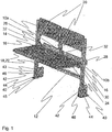
- FIG. 1 is shown as an example a perspective view of a folding seat according to the invention.
- the seat has two adjacent essentially parallel vertical rod-like leg parts, a first leg part 10a and a second leg part 10b, which are connected to each other with a horizontal rod-like horizontal brace 12.
- the upwards pointing second end of the intermediate support settles essentially on the same height level as the upwards pointing second ends of the leg parts.
- On the first surface of the leg parts and the intermediate support is a seat support 16.
- the seat support is a protruding part, which is essentially in a horizontal position and preferably 10-20 cm long, which is attached at its first end to the leg part or intermediate support in a fixed manner.
- the seat support, leg part and intermediate support are manufactured of the same metallic pipe profile.
- the folding seat shown in Figure 1 has two adjacent seat levels 18 and two adjacent backrests 20.
- the seat levels comprise a plate-like seat plate 22, on the opposite edges of the underside of which two parallel edge supports 24 are attached.
- the edge supports are sculptured metallic angle sections, one edge of which settles against the underside of the seat plate.
- the edge supports are attached to the ends of the seat supports 16 with pivot pins 30 so that when the edge supports are in the horizontal position according to Figure 1 , their first part extends to the first side of the level defined by the leg parts 10a, 10b, and their second part extends to the second side of the level defined by the leg parts.
- the second ends of the edge supports are connected to each other with an elongated connecting plate 28.
- Plate-like limiters 32 have been attached to the surface of the leg parts 10a, 10b which point towards the intermediate support 14, and to the surfaces of the intermediate support which point towards the leg parts.
- the limiters have a counter surface, which settles against the surface of the edge support, when the seat levels are in the essentially horizontal position according to Figure 1 .
- the limiter functions as a support, which prevents the seat level from rotating around the pivot pin 30 downwards from the position shown in Figure 1 , when the seat level is burdened with a downwards directed burden, such as the weight of a sitter.
- the limiters do not, however, prevent the seat level from rotating upwards from the position shown in Figure 1 .
- the seat level is attached at its edges to the first parts of the edge supports with screws, staples or some other mechanical attaching means.
- the backrests 20 are plate-like parts, which are attached at their first vertical edge in the vicinity of the second end of the leg part, and at their second vertical edge in the vicinity of the second end of the intermediate support.
- the backrests and seat plates are manufactured from some suitable, sculptable, plate-like material, such as plastic or a plate with a wooden base.
- the folding seat according to the invention further includes one support member 40 for each leg part, with the aid of which support member the seats are attached to the base.
- the support member are sculptured, plate-like parts, preferably manufactured from a metallic material, which have a first side 42, which settles against the leg part of the seat, and a second side 44, which settles against the base.
- the leg parts of the seat are attached to the first side of the support member using a mounting pin 46, which is attached in a detachable manner to the leg part near its first end.
- the mounting pin is a bolt, which is rotated into the threaded mounting hole in the leg part.
- the bolt may have a sculptured head, whereby a special key is needed for attaching and detaching the bolt.
- In the first edge 42 of the support member there is an elongated, vertical first hole 43 to be penetrated by the mounting pin and in the second edge 44 of the support member there is a second hole 45 to be penetrated by the first end of the leg part.
- Figure 2 is shown as an example a side view of the seat shown in Figure 1 .
- the Figure shows the seat in the use position, i.e. in the position where it is when a sitter positions himself to sit on it.
- the seat level 18 is settled in an essentially horizontal first extreme position according to Figure 2 .
- the extreme position of the seat level is defined by the limiter 32, which stops the rotating movement of the seat level around the pivot pin 30, when the edge support 24 of the seat hits the limiter 32.
- the seat level When there is no sitter on the seat, its seat level can be folded into a vertical position by rotating the seat level clockwise around the pivot pin 30. When the seat level is rotated enough, it settles into the second extreme position, where the edge supports of the seat level are essentially parallel to the leg parts 10a, 10b. The seat is thereby in a position, where it takes very little room in the depth direction. In a ready-built spectator stand structure this position enables for example the spectators to move smoothly between the seat rows.
- the connecting plate 28 in the second end of the edge supports functions as a counter weight, which attempts to rotate the seat level clockwise towards the second extreme position and thus reduces the force needed for folding the seat level.
- the mass of the connecting plate is so large that when in an unburdened state the seat level settles automatically in the above-described second extreme position.
- the backrest 20 of the seat functions as a limiter, which prevents the seat level from rotating further than the second extreme position.
- a support member 40 which is meant to be pivotably attached at its second edge to the base 100.
- the attaching is realized using mechanical attaching means, such as screws.
- the bond between the leg part and the support member realized with the aid of the first and second hole thus is a stiff bond, which prevents the rotation of the leg part when the first end of the leg part is fitted into the second hole 45 of the support member 40.
- FIG 3 is shown as an example the seat shown in Figure 2 in the storage position, where the leg parts, backrest and seat level of the seat are settled in a substantially horizontal position against the base.
- the seat according to the invention is moved from the use position shown in Figure 2 to the storage position shown in Figure 3 simply by setting the seat level into the second extreme position and lifting the entire seat upwards slightly.
- the first ends of the leg parts of the seat thus rise out from the second holes 45 in the support members 40 and the mounting pin 46 moves to the upper, second end of the first hole 43.
- the leg parts are rotated forward around the mounting pin into the storage position according to Figure 3 .
- the seat is moved back into the use position by performing the above-mentioned procedures in a reversed order.
- FIG 4 a spectator stand element according to the invention, which has folding seats according to the invention.
- the spectator stand element has a horizontal base 100, whereon is supported a plate-like walking level 52.
- the structure of the base may be a uniform plate-like part, the size of which is essentially the size of the entire spectator stand element, or it may comprise a number of adjacent, separate panel-like parts, which are in the direction of the end edges of the spectator stand element.
- a plate-like front edge 54 In the first edge of the base has been attached a plate-like front edge 54 and in its second edge has been attached a plate-like rear edge 56, which is essentially parallel to and of the same size as the front edge.
- the front edge and rear edge are attached to the base so that they form an essentially right angle with the base and the downward pointing surface of the front and rear edge settles essentially on the same height level as the underside of the base.
- On the base, right next to the rear edge have been attached support members 40, for attaching folding seats according to the invention.
- the spectator stand element can be manufactured in different lengths, whereby the number of seats to be attached to one element may vary.
- the seats are attached to the support members in a detachable manner using mounting pins (not shown in the Figure), which are fitted to pass through the first hole 43 of the support member.
- a mounting hole 47 for receiving the mounting pin.
- the mounting pin is a bolt, which has a sculptured head, and the mounting hole has threads for screwing in the bolt.
- the spectator stand element according to the invention further comprises one or more separate cover plates 58, which can be attached to the spectator stand element in place of the seat, which has been detached from it.
- cover plates 58 On the underside of the cover plate there are support rails 60, in the first end of which there are mounting holes 47.
- the cover plate is installed into place by attaching the support rails from their first end using a mounting pin to the first hole 43 of the support member 40 and by setting the second edge of the cover plate to rest on the front edge 54.
- the spectator stand element covered with the cover plate can function as a standing spectator stand, a walking level or a part of a staircase.
- Wheels 66 have been attached to the underside of the beam, which wheels enable the moving of the spectator stand element by pushing it from one place to another.
- the beam is manufactured from a U profile of a metallic material, and the wheels have been installed inside the profile, so that just a part of them can be seen.
- a breaking device (not shown in the Figure) has been arranged in connection with the wheels, with which breaking device at least a part of the wheels can be locked in a non-rotatable position.
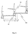
- FIG. 5 is shown as an example a manner in which the spectator stand elements according to an embodiment of the invention can be arranged in connection with each other.
- the spectator stand elements have been arranged in subsequent rows so that a spectator stand is formed, which rises toward the back.
- the rear edge of a spectator stand element on a lower height level carries the front edge of a spectator stand element on a higher height level.
- the first edge of the base 100 of a spectator stand element on a higher height level and the plate-like front edge 54 attached to the first edge of the base is supported on the upper surface of the support members 40 of a spectator stand element on a lower height level.
Landscapes
- Engineering & Computer Science (AREA)
- Architecture (AREA)
- Health & Medical Sciences (AREA)
- Dentistry (AREA)
- General Health & Medical Sciences (AREA)
- Civil Engineering (AREA)
- Structural Engineering (AREA)
- Chairs For Special Purposes, Such As Reclining Chairs (AREA)
- Special Chairs (AREA)
Claims (20)
- Klappsitz mit wenigstens zwei Beinteilen (10a, 10b), wenigstens einer Sitzfläche (18), die schwenkbar an den Beinteilen befestigt ist, und einem Stützteil (40), das im ersten Ende jedes Beinteils angebracht ist, um das Beinteil an einer Basis (100) zu befestigen, wobei das Beinteil am Stützteil mittels eines Befestigungsstifts (46) schwenkbar befestigt ist,
dadurch gekennzeichnet, dass
das Stützteil eine erste Kante (42) hat, die am Beinteil des Sitzes anliegt, wobei die Kante ein erstes Langloch (43) für den Befestigungsstift (46) hat, und eine zweite Kante (44), die an der Basis anliegt, wobei die zweite Kante ein Verriegelungsteil zum Aufnehmen und Arretieren des ersten Endes des Beinteils hat. - Sitz nach Anspruch 1, dadurch gekennzeichnet, dass das Verriegelungsteil in der zweiten Kante (44) ein zweites Loch (45) oder eine Öffnung ist, in das / die das erste Ende des Beinteils (10a, 10b) eingesteckt werden kann.
- Sitz nach Anspruch 2, dadurch gekennzeichnet, dass das zweite Loch (45) eine Durchgangsbohrung ist, wobei das in dieses Loch eingesteckte erste Ende des Beinteils (10a, 10b) ausgelegt ist, um sich selbst auf der Basis (100) zu stützen.
- Sitz nach einem der Ansprüche 1 bis 3, dadurch gekennzeichnet, dass das erste Ende des Beinteils (10a, 10b) ausgelegt ist, um gelöst zu werden, wenn das Beinteil so weit, wie es das erste Langloch (43) zulässt, nach oben gezogen wird.
- Sitz nach einem der Ansprüche 1 bis 4, dadurch gekennzeichnet, dass der Befestigungsstift (46) abnehmbar an dem Beinteil (10a, 10b) befestigt ist.
- Sitz nach einem der Ansprüche 1 bis 5, dadurch gekennzeichnet, dass der Befestigungsstift (46) eine Schraube ist, und dass das Beinteil ein mit Gewinde versehenes Befestigungsloch (47) hat, um die Schraube aufzunehmen.
- Sitz nach Anspruch 6, dadurch gekennzeichnet, dass die Schraube einen geformten Kopf hat, so dass die Schraube nur mit einem speziellen Schlüssel, der für den Kopf passt, entfernt werden kann.
- Sitz nach einem der Ansprüche 1 bis 7, dadurch gekennzeichnet, dass er des Weiteren wenigstens eine Lehne (20) hat, die nahe dem zweiten Ende des Beinteils (10a, 10b) befestigt ist.
- Sitz nach Anspruch 8, dadurch gekennzeichnet, dass er in eine Lagerposition geklappt werden kann, in der die Beinteile (10a, 10b), die Lehne (20) und die Sitzfläche (18) des Sitzes in im Wesentlichen horizontaler Position auf der Basis (100) ruhen.
- Zuschauertribünenelement, das eine Basis (100) und wenigstens einen Klappsitz aufweist, der abnehmbar an der Basis befestigt ist, wobei der Sitz wenigstens zwei Beinteile (10a, 10b), wenigstens eine Sitzfläche (18), die schwenkbar an den Beinteilen befestigt ist, und ein Stützteil (40) hat, das im ersten Ende jedes Beinteils angebracht ist, um das Beinteil an der Basis (100) zu befestigen, wobei das Beinteil am Stützteil mittels eines Befestigungsstifts (46) schwenkbar befestigt ist, dadurch gekennzeichnet, dass
das Stützteil eine erste Kante (42) hat, die am Beinteil des Sitzes anliegt, wobei die Kante ein erstes Langloch (43) für den Befestigungsstift (46) hat, und eine zweite Kante (44), die an der Basis anliegt, wobei die zweite Kante ein Verriegelungsteil zum Aufnehmen und Arretieren des ersten Endes des Beinteils hat. - Zuschauertribünenelement nach Anspruch 10, dadurch gekennzeichnet, dass das Verriegelungsteil in der zweiten Kante (44) ein zweites Loch (45) oder eine Öffnung ist, in das / die das erste Ende des Beinteils (10a, 10b) eingesteckt werden kann.
- Zuschauertribünenelement nach Anspruch 11, dadurch gekennzeichnet, dass das zweite Loch (45) eine Durchgangsbohrung ist, wobei das in dieses Loch eingesteckte erste Ende des Beinteils (10a, 10b) ausgelegt ist, um sich selbst auf der Basis (100) zu stützen.
- Zuschauertribünenelement nach einem der Ansprüche 10 bis 12, dadurch gekennzeichnet, dass es des Weiteren eine Abdeckplatte (58) aufweist, die anstelle des Sitzes, der vom Zuschauertribünenelement abgenommen worden ist, abnehmbar am Stützteil (40) befestigt werden kann.
- Zuschauertribünenelement nach einem der Ansprüche 10 bis 13, dadurch gekennzeichnet, dass es des Weiteren einen Stützrahmen zum Anheben der Basis (100) auf eine gewünschte Höhe vom Boden des Zuschauertribünenraums aufweist.
- Zuschauertribünenelement nach Anspruch 14, dadurch gekennzeichnet, dass es eine Hinterkante (56) hat, und dass der Stützrahmen wenigstens zwei horizontale Träger (62) aufweist, an denen Pfosten (64) in vertikaler Position befestigt sind, wobei die Pfosten an ihren nach oben zeigenden Enden an der Hinterkante (56) befestigt sind.
- Zuschauertribünenelement nach Anspruch 14 oder 15, dadurch gekennzeichnet, dass der Stützrahmen Räder (66) zum Bewegen des Zuschauertribünenelements hat.
- Stützteil zum Befestigen eines Beinteils (10a, 10b) eines Sitzes an einer Basis (100), dadurch gekennzeichnet, dass das Stützteil eine erste Kante (42) hat, die am Beinteil des Sitzes anliegt, wobei die erste Kante ein erstes Langloch (43) für einen Befestigungsstift (46) des Beinteils hat, und eine zweite Kante (44), die an der Basis anliegt, wobei die zweite Kante ein Verriegelungsteil zum Aufnehmen und Arretieren des ersten Endes des Beinteils hat.
- Stützteil nach Anspruch 17, dadurch gekennzeichnet, dass das Verriegelungsteil in der zweiten Kante ein zweites Loch (45) oder eine Öffnung ist, in das / die das erste Ende des Beinteils (10a, 10b) eingesteckt werden kann.
- Stützteil nach Anspruch 18, dadurch gekennzeichnet, dass das zweite Loch (45) eine Durchgangsbohrung ist, wobei das in dieses Loch eingesteckte erste Ende des Beinteils (10a, 10b) ausgelegt ist, um sich selbst auf der Basis (100) zu stützen.
- Stützteil nach einem der Ansprüche 17 bis 19, dadurch gekennzeichnet, dass die erste Kante (42) und die zweite Kante (44) plattenartige Teile sind, die im Wesentlichen rechtwinklig zueinander sind.
Applications Claiming Priority (2)
| Application Number | Priority Date | Filing Date | Title |
|---|---|---|---|
| FI20070818A FI119752B (fi) | 2007-10-29 | 2007-10-29 | Kokoontaitettava istuin, katsomoelementti ja istuimen tukielin |
| PCT/FI2008/050607 WO2009056678A1 (en) | 2007-10-29 | 2008-10-28 | Folding seat, spectator stand element and support member for seat |
Publications (2)
| Publication Number | Publication Date |
|---|---|
| EP2217112A1 EP2217112A1 (de) | 2010-08-18 |
| EP2217112B1 true EP2217112B1 (de) | 2012-05-16 |
Family
ID=38656827
Family Applications (1)
| Application Number | Title | Priority Date | Filing Date |
|---|---|---|---|
| EP08846091A Active EP2217112B1 (de) | 2007-10-29 | 2008-10-28 | Klappsitz, zuschauerstandelement und stützelement für den sitz |
Country Status (3)
| Country | Link |
|---|---|
| EP (1) | EP2217112B1 (de) |
| FI (1) | FI119752B (de) |
| WO (1) | WO2009056678A1 (de) |
Families Citing this family (1)
| Publication number | Priority date | Publication date | Assignee | Title |
|---|---|---|---|---|
| CN111877814A (zh) * | 2020-07-21 | 2020-11-03 | 上海建工二建集团有限公司 | 预制清水混凝土看台板的施工方法 |
Family Cites Families (2)
| Publication number | Priority date | Publication date | Assignee | Title |
|---|---|---|---|---|
| GB1261203A (en) * | 1968-01-24 | 1972-01-26 | Pel Ltd | Folding seats |
| CN1129384C (zh) * | 2000-06-10 | 2003-12-03 | 丰国勋 | 一种排椅翻放定位装置 |
-
2007
- 2007-10-29 FI FI20070818A patent/FI119752B/fi not_active IP Right Cessation
-
2008
- 2008-10-28 WO PCT/FI2008/050607 patent/WO2009056678A1/en not_active Ceased
- 2008-10-28 EP EP08846091A patent/EP2217112B1/de active Active
Also Published As
| Publication number | Publication date |
|---|---|
| EP2217112A1 (de) | 2010-08-18 |
| WO2009056678A1 (en) | 2009-05-07 |
| FI20070818A0 (fi) | 2007-10-29 |
| FI119752B (fi) | 2009-03-13 |
Similar Documents
| Publication | Publication Date | Title |
|---|---|---|
| US8438786B2 (en) | Flexible venue system | |
| US9756935B2 (en) | Convertible, integral, dining table, coffee table, serving table, desk, bed, bench and beach lounger utilizing a unique hinging system | |
| KR101488825B1 (ko) | 수납식 관람석 | |
| US6625932B1 (en) | Variable rise vertically retractable arena seating assembly | |
| GB2068215A (en) | Improvements in shelf units | |
| KR20200000858U (ko) | 조립식 구조를 갖는 고소작업대 | |
| EP1772169B1 (de) | Ratschenaufzugssystem | |
| WO2009056678A1 (en) | Folding seat, spectator stand element and support member for seat | |
| US20180001218A1 (en) | System for a tilting amusement ride | |
| KR101917946B1 (ko) | 스탠딩 데스크 | |
| JP3352089B2 (ja) | 多重折畳みステージ | |
| CN1217086C (zh) | 自调平的支撑 | |
| CN1361670A (zh) | 便携式座椅以及用于该座椅的锁定装置 | |
| US12312829B2 (en) | System and method for preventing access to steps in retracted bleachers | |
| KR20180086910A (ko) | 낚싯대 받침대의 각도조정장치 및 이를 적용한 좌대 | |
| CN214615225U (zh) | 一种便于安装的组合式地板 | |
| JP4514893B2 (ja) | 階段へのレール取り付け構造 | |
| DE20316254U1 (de) | Hochstuhl für Kinder | |
| JP5364950B2 (ja) | 移動観覧席 | |
| CN217353454U (zh) | 脚手架坡度自适应结构 | |
| CA3032721A1 (en) | Basketball backboard lift system | |
| CN204273637U (zh) | 一种调整面板高度的装置 | |
| KR20190042880A (ko) | 휴게설치물 | |
| JP5166083B2 (ja) | 可動床 | |
| JP4262511B2 (ja) | 縦型遊技機の枠構造 |
Legal Events
| Date | Code | Title | Description |
|---|---|---|---|
| PUAI | Public reference made under article 153(3) epc to a published international application that has entered the european phase |
Free format text: ORIGINAL CODE: 0009012 |
|
| 17P | Request for examination filed |
Effective date: 20100429 |
|
| AK | Designated contracting states |
Kind code of ref document: A1 Designated state(s): AT BE BG CH CY CZ DE DK EE ES FI FR GB GR HR HU IE IS IT LI LT LU LV MC MT NL NO PL PT RO SE SI SK TR |
|
| AX | Request for extension of the european patent |
Extension state: AL BA MK RS |
|
| GRAP | Despatch of communication of intention to grant a patent |
Free format text: ORIGINAL CODE: EPIDOSNIGR1 |
|
| RIC1 | Information provided on ipc code assigned before grant |
Ipc: E04H 3/12 20060101ALI20111031BHEP Ipc: A47C 1/126 20060101AFI20111031BHEP |
|
| GRAS | Grant fee paid |
Free format text: ORIGINAL CODE: EPIDOSNIGR3 |
|
| GRAA | (expected) grant |
Free format text: ORIGINAL CODE: 0009210 |
|
| AK | Designated contracting states |
Kind code of ref document: B1 Designated state(s): AT BE BG CH CY CZ DE DK EE ES FI FR GB GR HR HU IE IS IT LI LT LU LV MC MT NL NO PL PT RO SE SI SK TR |
|
| AX | Request for extension of the european patent |
Extension state: AL BA MK RS |
|
| REG | Reference to a national code |
Ref country code: GB Ref legal event code: FG4D |
|
| REG | Reference to a national code |
Ref country code: CH Ref legal event code: EP |
|
| REG | Reference to a national code |
Ref country code: AT Ref legal event code: REF Ref document number: 557616 Country of ref document: AT Kind code of ref document: T Effective date: 20120615 |
|
| REG | Reference to a national code |
Ref country code: IE Ref legal event code: FG4D |
|
| REG | Reference to a national code |
Ref country code: DE Ref legal event code: R096 Ref document number: 602008015737 Country of ref document: DE Effective date: 20120712 |
|
| REG | Reference to a national code |
Ref country code: NL Ref legal event code: VDEP Effective date: 20120516 |
|
| REG | Reference to a national code |
Ref country code: LT Ref legal event code: MG4D Effective date: 20120516 |
|
| PG25 | Lapsed in a contracting state [announced via postgrant information from national office to epo] |
Ref country code: PL Free format text: LAPSE BECAUSE OF FAILURE TO SUBMIT A TRANSLATION OF THE DESCRIPTION OR TO PAY THE FEE WITHIN THE PRESCRIBED TIME-LIMIT Effective date: 20120516 Ref country code: IS Free format text: LAPSE BECAUSE OF FAILURE TO SUBMIT A TRANSLATION OF THE DESCRIPTION OR TO PAY THE FEE WITHIN THE PRESCRIBED TIME-LIMIT Effective date: 20120916 Ref country code: SE Free format text: LAPSE BECAUSE OF FAILURE TO SUBMIT A TRANSLATION OF THE DESCRIPTION OR TO PAY THE FEE WITHIN THE PRESCRIBED TIME-LIMIT Effective date: 20120516 Ref country code: NO Free format text: LAPSE BECAUSE OF FAILURE TO SUBMIT A TRANSLATION OF THE DESCRIPTION OR TO PAY THE FEE WITHIN THE PRESCRIBED TIME-LIMIT Effective date: 20120816 Ref country code: CY Free format text: LAPSE BECAUSE OF FAILURE TO SUBMIT A TRANSLATION OF THE DESCRIPTION OR TO PAY THE FEE WITHIN THE PRESCRIBED TIME-LIMIT Effective date: 20120516 Ref country code: LT Free format text: LAPSE BECAUSE OF FAILURE TO SUBMIT A TRANSLATION OF THE DESCRIPTION OR TO PAY THE FEE WITHIN THE PRESCRIBED TIME-LIMIT Effective date: 20120516 Ref country code: FI Free format text: LAPSE BECAUSE OF FAILURE TO SUBMIT A TRANSLATION OF THE DESCRIPTION OR TO PAY THE FEE WITHIN THE PRESCRIBED TIME-LIMIT Effective date: 20120516 |
|
| REG | Reference to a national code |
Ref country code: AT Ref legal event code: MK05 Ref document number: 557616 Country of ref document: AT Kind code of ref document: T Effective date: 20120516 |
|
| PG25 | Lapsed in a contracting state [announced via postgrant information from national office to epo] |
Ref country code: HR Free format text: LAPSE BECAUSE OF FAILURE TO SUBMIT A TRANSLATION OF THE DESCRIPTION OR TO PAY THE FEE WITHIN THE PRESCRIBED TIME-LIMIT Effective date: 20120516 Ref country code: SI Free format text: LAPSE BECAUSE OF FAILURE TO SUBMIT A TRANSLATION OF THE DESCRIPTION OR TO PAY THE FEE WITHIN THE PRESCRIBED TIME-LIMIT Effective date: 20120516 Ref country code: GR Free format text: LAPSE BECAUSE OF FAILURE TO SUBMIT A TRANSLATION OF THE DESCRIPTION OR TO PAY THE FEE WITHIN THE PRESCRIBED TIME-LIMIT Effective date: 20120817 Ref country code: PT Free format text: LAPSE BECAUSE OF FAILURE TO SUBMIT A TRANSLATION OF THE DESCRIPTION OR TO PAY THE FEE WITHIN THE PRESCRIBED TIME-LIMIT Effective date: 20120917 Ref country code: LV Free format text: LAPSE BECAUSE OF FAILURE TO SUBMIT A TRANSLATION OF THE DESCRIPTION OR TO PAY THE FEE WITHIN THE PRESCRIBED TIME-LIMIT Effective date: 20120516 |
|
| PG25 | Lapsed in a contracting state [announced via postgrant information from national office to epo] |
Ref country code: BE Free format text: LAPSE BECAUSE OF FAILURE TO SUBMIT A TRANSLATION OF THE DESCRIPTION OR TO PAY THE FEE WITHIN THE PRESCRIBED TIME-LIMIT Effective date: 20120516 |
|
| PG25 | Lapsed in a contracting state [announced via postgrant information from national office to epo] |
Ref country code: NL Free format text: LAPSE BECAUSE OF FAILURE TO SUBMIT A TRANSLATION OF THE DESCRIPTION OR TO PAY THE FEE WITHIN THE PRESCRIBED TIME-LIMIT Effective date: 20120516 Ref country code: CZ Free format text: LAPSE BECAUSE OF FAILURE TO SUBMIT A TRANSLATION OF THE DESCRIPTION OR TO PAY THE FEE WITHIN THE PRESCRIBED TIME-LIMIT Effective date: 20120516 Ref country code: AT Free format text: LAPSE BECAUSE OF FAILURE TO SUBMIT A TRANSLATION OF THE DESCRIPTION OR TO PAY THE FEE WITHIN THE PRESCRIBED TIME-LIMIT Effective date: 20120516 Ref country code: SK Free format text: LAPSE BECAUSE OF FAILURE TO SUBMIT A TRANSLATION OF THE DESCRIPTION OR TO PAY THE FEE WITHIN THE PRESCRIBED TIME-LIMIT Effective date: 20120516 Ref country code: DK Free format text: LAPSE BECAUSE OF FAILURE TO SUBMIT A TRANSLATION OF THE DESCRIPTION OR TO PAY THE FEE WITHIN THE PRESCRIBED TIME-LIMIT Effective date: 20120516 Ref country code: RO Free format text: LAPSE BECAUSE OF FAILURE TO SUBMIT A TRANSLATION OF THE DESCRIPTION OR TO PAY THE FEE WITHIN THE PRESCRIBED TIME-LIMIT Effective date: 20120516 Ref country code: EE Free format text: LAPSE BECAUSE OF FAILURE TO SUBMIT A TRANSLATION OF THE DESCRIPTION OR TO PAY THE FEE WITHIN THE PRESCRIBED TIME-LIMIT Effective date: 20120516 |
|
| PG25 | Lapsed in a contracting state [announced via postgrant information from national office to epo] |
Ref country code: IT Free format text: LAPSE BECAUSE OF FAILURE TO SUBMIT A TRANSLATION OF THE DESCRIPTION OR TO PAY THE FEE WITHIN THE PRESCRIBED TIME-LIMIT Effective date: 20120516 |
|
| PLBE | No opposition filed within time limit |
Free format text: ORIGINAL CODE: 0009261 |
|
| STAA | Information on the status of an ep patent application or granted ep patent |
Free format text: STATUS: NO OPPOSITION FILED WITHIN TIME LIMIT |
|
| 26N | No opposition filed |
Effective date: 20130219 |
|
| PG25 | Lapsed in a contracting state [announced via postgrant information from national office to epo] |
Ref country code: ES Free format text: LAPSE BECAUSE OF FAILURE TO SUBMIT A TRANSLATION OF THE DESCRIPTION OR TO PAY THE FEE WITHIN THE PRESCRIBED TIME-LIMIT Effective date: 20120827 |
|
| PG25 | Lapsed in a contracting state [announced via postgrant information from national office to epo] |
Ref country code: MC Free format text: LAPSE BECAUSE OF NON-PAYMENT OF DUE FEES Effective date: 20121031 |
|
| REG | Reference to a national code |
Ref country code: CH Ref legal event code: PL |
|
| REG | Reference to a national code |
Ref country code: DE Ref legal event code: R097 Ref document number: 602008015737 Country of ref document: DE Effective date: 20130219 |
|
| GBPC | Gb: european patent ceased through non-payment of renewal fee |
Effective date: 20121028 |
|
| REG | Reference to a national code |
Ref country code: FR Ref legal event code: ST Effective date: 20130628 |
|
| PG25 | Lapsed in a contracting state [announced via postgrant information from national office to epo] |
Ref country code: GB Free format text: LAPSE BECAUSE OF NON-PAYMENT OF DUE FEES Effective date: 20121028 Ref country code: BG Free format text: LAPSE BECAUSE OF FAILURE TO SUBMIT A TRANSLATION OF THE DESCRIPTION OR TO PAY THE FEE WITHIN THE PRESCRIBED TIME-LIMIT Effective date: 20120816 Ref country code: DE Free format text: LAPSE BECAUSE OF NON-PAYMENT OF DUE FEES Effective date: 20130501 Ref country code: CH Free format text: LAPSE BECAUSE OF NON-PAYMENT OF DUE FEES Effective date: 20121031 Ref country code: LI Free format text: LAPSE BECAUSE OF NON-PAYMENT OF DUE FEES Effective date: 20121031 |
|
| REG | Reference to a national code |
Ref country code: IE Ref legal event code: MM4A |
|
| REG | Reference to a national code |
Ref country code: DE Ref legal event code: R119 Ref document number: 602008015737 Country of ref document: DE Effective date: 20130501 |
|
| PG25 | Lapsed in a contracting state [announced via postgrant information from national office to epo] |
Ref country code: FR Free format text: LAPSE BECAUSE OF NON-PAYMENT OF DUE FEES Effective date: 20121031 |
|
| PG25 | Lapsed in a contracting state [announced via postgrant information from national office to epo] |
Ref country code: IE Free format text: LAPSE BECAUSE OF NON-PAYMENT OF DUE FEES Effective date: 20121028 |
|
| PG25 | Lapsed in a contracting state [announced via postgrant information from national office to epo] |
Ref country code: MT Free format text: LAPSE BECAUSE OF FAILURE TO SUBMIT A TRANSLATION OF THE DESCRIPTION OR TO PAY THE FEE WITHIN THE PRESCRIBED TIME-LIMIT Effective date: 20120516 |
|
| PG25 | Lapsed in a contracting state [announced via postgrant information from national office to epo] |
Ref country code: TR Free format text: LAPSE BECAUSE OF FAILURE TO SUBMIT A TRANSLATION OF THE DESCRIPTION OR TO PAY THE FEE WITHIN THE PRESCRIBED TIME-LIMIT Effective date: 20120516 |
|
| PG25 | Lapsed in a contracting state [announced via postgrant information from national office to epo] |
Ref country code: LU Free format text: LAPSE BECAUSE OF NON-PAYMENT OF DUE FEES Effective date: 20121028 |
|
| PG25 | Lapsed in a contracting state [announced via postgrant information from national office to epo] |
Ref country code: HU Free format text: LAPSE BECAUSE OF FAILURE TO SUBMIT A TRANSLATION OF THE DESCRIPTION OR TO PAY THE FEE WITHIN THE PRESCRIBED TIME-LIMIT Effective date: 20081028 |