EP2218603A1 - Hybridantrieb - Google Patents
Hybridantrieb Download PDFInfo
- Publication number
- EP2218603A1 EP2218603A1 EP10001246A EP10001246A EP2218603A1 EP 2218603 A1 EP2218603 A1 EP 2218603A1 EP 10001246 A EP10001246 A EP 10001246A EP 10001246 A EP10001246 A EP 10001246A EP 2218603 A1 EP2218603 A1 EP 2218603A1
- Authority
- EP
- European Patent Office
- Prior art keywords
- hybrid vehicle
- vehicle according
- gear
- electric machine
- planetary gear
- Prior art date
- Legal status (The legal status is an assumption and is not a legal conclusion. Google has not performed a legal analysis and makes no representation as to the accuracy of the status listed.)
- Granted
Links
Images


Classifications
-
- B—PERFORMING OPERATIONS; TRANSPORTING
- B60—VEHICLES IN GENERAL
- B60K—ARRANGEMENT OR MOUNTING OF PROPULSION UNITS OR OF TRANSMISSIONS IN VEHICLES; ARRANGEMENT OR MOUNTING OF PLURAL DIVERSE PRIME-MOVERS IN VEHICLES; AUXILIARY DRIVES FOR VEHICLES; INSTRUMENTATION OR DASHBOARDS FOR VEHICLES; ARRANGEMENTS IN CONNECTION WITH COOLING, AIR INTAKE, GAS EXHAUST OR FUEL SUPPLY OF PROPULSION UNITS IN VEHICLES
- B60K6/00—Arrangement or mounting of plural diverse prime-movers for mutual or common propulsion, e.g. hybrid propulsion systems comprising electric motors and internal combustion engines
- B60K6/20—Arrangement or mounting of plural diverse prime-movers for mutual or common propulsion, e.g. hybrid propulsion systems comprising electric motors and internal combustion engines the prime-movers consisting of electric motors and internal combustion engines, e.g. HEVs
- B60K6/22—Arrangement or mounting of plural diverse prime-movers for mutual or common propulsion, e.g. hybrid propulsion systems comprising electric motors and internal combustion engines the prime-movers consisting of electric motors and internal combustion engines, e.g. HEVs characterised by apparatus, components or means specially adapted for HEVs
- B60K6/36—Arrangement or mounting of plural diverse prime-movers for mutual or common propulsion, e.g. hybrid propulsion systems comprising electric motors and internal combustion engines the prime-movers consisting of electric motors and internal combustion engines, e.g. HEVs characterised by apparatus, components or means specially adapted for HEVs characterised by the transmission gearings
- B60K6/365—Arrangement or mounting of plural diverse prime-movers for mutual or common propulsion, e.g. hybrid propulsion systems comprising electric motors and internal combustion engines the prime-movers consisting of electric motors and internal combustion engines, e.g. HEVs characterised by apparatus, components or means specially adapted for HEVs characterised by the transmission gearings with the gears having orbital motion
-
- B—PERFORMING OPERATIONS; TRANSPORTING
- B60—VEHICLES IN GENERAL
- B60K—ARRANGEMENT OR MOUNTING OF PROPULSION UNITS OR OF TRANSMISSIONS IN VEHICLES; ARRANGEMENT OR MOUNTING OF PLURAL DIVERSE PRIME-MOVERS IN VEHICLES; AUXILIARY DRIVES FOR VEHICLES; INSTRUMENTATION OR DASHBOARDS FOR VEHICLES; ARRANGEMENTS IN CONNECTION WITH COOLING, AIR INTAKE, GAS EXHAUST OR FUEL SUPPLY OF PROPULSION UNITS IN VEHICLES
- B60K6/00—Arrangement or mounting of plural diverse prime-movers for mutual or common propulsion, e.g. hybrid propulsion systems comprising electric motors and internal combustion engines
- B60K6/20—Arrangement or mounting of plural diverse prime-movers for mutual or common propulsion, e.g. hybrid propulsion systems comprising electric motors and internal combustion engines the prime-movers consisting of electric motors and internal combustion engines, e.g. HEVs
- B60K6/42—Arrangement or mounting of plural diverse prime-movers for mutual or common propulsion, e.g. hybrid propulsion systems comprising electric motors and internal combustion engines the prime-movers consisting of electric motors and internal combustion engines, e.g. HEVs characterised by the architecture of the hybrid electric vehicle
- B60K6/44—Series-parallel type
- B60K6/445—Differential gearing distribution type
-
- B—PERFORMING OPERATIONS; TRANSPORTING
- B60—VEHICLES IN GENERAL
- B60K—ARRANGEMENT OR MOUNTING OF PROPULSION UNITS OR OF TRANSMISSIONS IN VEHICLES; ARRANGEMENT OR MOUNTING OF PLURAL DIVERSE PRIME-MOVERS IN VEHICLES; AUXILIARY DRIVES FOR VEHICLES; INSTRUMENTATION OR DASHBOARDS FOR VEHICLES; ARRANGEMENTS IN CONNECTION WITH COOLING, AIR INTAKE, GAS EXHAUST OR FUEL SUPPLY OF PROPULSION UNITS IN VEHICLES
- B60K1/00—Arrangement or mounting of electrical propulsion units
- B60K1/02—Arrangement or mounting of electrical propulsion units comprising more than one electric motor
-
- B—PERFORMING OPERATIONS; TRANSPORTING
- B60—VEHICLES IN GENERAL
- B60K—ARRANGEMENT OR MOUNTING OF PROPULSION UNITS OR OF TRANSMISSIONS IN VEHICLES; ARRANGEMENT OR MOUNTING OF PLURAL DIVERSE PRIME-MOVERS IN VEHICLES; AUXILIARY DRIVES FOR VEHICLES; INSTRUMENTATION OR DASHBOARDS FOR VEHICLES; ARRANGEMENTS IN CONNECTION WITH COOLING, AIR INTAKE, GAS EXHAUST OR FUEL SUPPLY OF PROPULSION UNITS IN VEHICLES
- B60K1/00—Arrangement or mounting of electrical propulsion units
- B60K1/04—Arrangement or mounting of electrical propulsion units of the electric storage means for propulsion
-
- B—PERFORMING OPERATIONS; TRANSPORTING
- B60—VEHICLES IN GENERAL
- B60K—ARRANGEMENT OR MOUNTING OF PROPULSION UNITS OR OF TRANSMISSIONS IN VEHICLES; ARRANGEMENT OR MOUNTING OF PLURAL DIVERSE PRIME-MOVERS IN VEHICLES; AUXILIARY DRIVES FOR VEHICLES; INSTRUMENTATION OR DASHBOARDS FOR VEHICLES; ARRANGEMENTS IN CONNECTION WITH COOLING, AIR INTAKE, GAS EXHAUST OR FUEL SUPPLY OF PROPULSION UNITS IN VEHICLES
- B60K1/00—Arrangement or mounting of electrical propulsion units
- B60K1/04—Arrangement or mounting of electrical propulsion units of the electric storage means for propulsion
- B60K2001/0405—Arrangement or mounting of electrical propulsion units of the electric storage means for propulsion characterised by their position
- B60K2001/0438—Arrangement under the floor
-
- F—MECHANICAL ENGINEERING; LIGHTING; HEATING; WEAPONS; BLASTING
- F16—ENGINEERING ELEMENTS AND UNITS; GENERAL MEASURES FOR PRODUCING AND MAINTAINING EFFECTIVE FUNCTIONING OF MACHINES OR INSTALLATIONS; THERMAL INSULATION IN GENERAL
- F16H—GEARING
- F16H37/00—Combinations of mechanical gearings, not provided for in groups F16H1/00 - F16H35/00
- F16H37/02—Combinations of mechanical gearings, not provided for in groups F16H1/00 - F16H35/00 comprising essentially only toothed or friction gearings
- F16H37/06—Combinations of mechanical gearings, not provided for in groups F16H1/00 - F16H35/00 comprising essentially only toothed or friction gearings with a plurality of driving or driven shafts; with arrangements for dividing torque between two or more intermediate shafts
- F16H37/08—Combinations of mechanical gearings, not provided for in groups F16H1/00 - F16H35/00 comprising essentially only toothed or friction gearings with a plurality of driving or driven shafts; with arrangements for dividing torque between two or more intermediate shafts with differential gearing
- F16H37/0833—Combinations of mechanical gearings, not provided for in groups F16H1/00 - F16H35/00 comprising essentially only toothed or friction gearings with a plurality of driving or driven shafts; with arrangements for dividing torque between two or more intermediate shafts with differential gearing with arrangements for dividing torque between two or more intermediate shafts, i.e. with two or more internal power paths
- F16H37/084—Combinations of mechanical gearings, not provided for in groups F16H1/00 - F16H35/00 comprising essentially only toothed or friction gearings with a plurality of driving or driven shafts; with arrangements for dividing torque between two or more intermediate shafts with differential gearing with arrangements for dividing torque between two or more intermediate shafts, i.e. with two or more internal power paths at least one power path being a continuously variable transmission, i.e. CVT
- F16H2037/088—Power-split transmissions with summing differentials, with the input of the CVT connected or connectable to the input shaft
-
- Y—GENERAL TAGGING OF NEW TECHNOLOGICAL DEVELOPMENTS; GENERAL TAGGING OF CROSS-SECTIONAL TECHNOLOGIES SPANNING OVER SEVERAL SECTIONS OF THE IPC; TECHNICAL SUBJECTS COVERED BY FORMER USPC CROSS-REFERENCE ART COLLECTIONS [XRACs] AND DIGESTS
- Y02—TECHNOLOGIES OR APPLICATIONS FOR MITIGATION OR ADAPTATION AGAINST CLIMATE CHANGE
- Y02T—CLIMATE CHANGE MITIGATION TECHNOLOGIES RELATED TO TRANSPORTATION
- Y02T10/00—Road transport of goods or passengers
- Y02T10/60—Other road transportation technologies with climate change mitigation effect
- Y02T10/62—Hybrid vehicles
Definitions
- the present invention relates to a hybrid vehicle according to the preamble of claim 1.
- Combustion engines are still the main propulsion source in hybrid vehicles currently available on the market.
- An "extension" of a conventional internal combustion engine engine to “hybrid components” results in a relatively high vehicle weight, which does not necessarily indicate “environmental disclaimer”.
- the "high-voltage storage” used in today's hybrid vehicles which are needed to supply the “electric drive” with electrical energy, make up a considerable additional mass.
- High-voltage accumulators are not only heavy but also expensive and require special safety precautions in the vehicle due to the high electrical voltage.
- today's hybrid vehicles can only complete comparatively short distances at relatively low speeds in the purely electric driving.
- the object of the invention is to provide a hybrid vehicle which has a compact drive train and which provides a comparatively low overall engine power a sufficiently high overall performance and thus a high ride comfort.
- the basic principle of the invention is to couple two electric machines via a planetary gear with a differential gear, wherein one of the two electric machines can be supported by a "comparatively small" internal combustion engine.
- the hybrid vehicle according to the invention comprises a differential gear having a differential case functioning as a transmission input and two transmission outputs formed by left and right output shafts.
- a first "torque transmitting element" of the planetary gear is coupled to the differential carrier of the differential gear.
- the first "torque transmitting element” may e.g. be formed by a toothing of the differential carrier or by a flanged to the differential carrier gear ring, which acts as a sun gear of the planetary gear.
- a "second" torque transmitting element of the planetary gear is coupled to a first of the two electric machines.
- the second torque transmitting element of the planetary gear may be formed by a planet carrier of the planetary gear.
- On the planet carrier a plurality of meshing with the first torque transmitting element planet gears are rotatably mounted.
- the third torque transmitting element may be formed by a ring gear of the planetary gear.
- the differential carrier acts as a transmission input of the differential gear.
- the electrical machines do not necessarily have to be at zero speed, but they can, for example, in the same direction, ie in the same direction but rotate with opposite moment direction. This has the advantage that the electric machines when starting the vehicle from a standing position need not overcome their respective "breakaway torque", which can avoid excessively high starting currents.
- the second electric machine can be coupled via a clutch to the internal combustion engine. If the second electric machine is in the drive mode, the internal combustion engine can be used for "boosting" when the clutch is closed, ie. H. as drive support for the second electric machine. On the other hand, if the second electric machine operates in the generator operating mode, electric motor energy can be generated by combustion engine when the clutch is closed and the internal combustion engine is running.
- the arrangement described above allows a very compact arrangement of the individual components both in a vehicle with front-wheel drive and in a vehicle with rear-wheel drive.
- the two electrical machines as well as the internal combustion engine and the clutch can be arranged in the immediate vicinity of the differential gear.
- the housing components of the electrical machines, the rear axle and the internal combustion engine can be flanged directly to each other or connected to a preassembled module together.
- a center tunnel extending in the longitudinal direction of the hybrid vehicle may be formed in the floor area of the body. At least in part of the space formed by the center tunnel "electrical energy storage" such. B. battery cells or capacitors may be arranged, which supply the electric machines with electrical energy or cache regeneratively recuperated energy.
- the electrical energy stores can be subdivided into two "strands" or "groups", of which each strand or each group is assigned to one of the two electrical machines.
- Each of the two strings or each of the two groups may have a nominal voltage in the range between 40 volts and 400 volts, e.g. 48 volts. At such low voltages, unlike the high voltage systems of conventional hybrid vehicles, no dedicated contact protection is required.
- each of the two electric machines provides an electromotive power in the range between 20 and 60 KW (eg each of 20 KW) and the internal combustion engine a drive power of approximately 20 KW.
- the internal combustion engine can thus be relatively compact and lightweight. It is conceivable, e.g. to a one-, two- or three-cylinder engine, as found in the motorcycle area.
- the hybrid vehicle may further be provided with an electrical interface, e.g. B. a "socket” equipped, which allows a "plug-in operation".
- an electrical interface e.g. B. a "socket" equipped, which allows a "plug-in operation”.
- the electrical system can be connected with the vehicle to the public power grid, which allows charging of electrical energy storage.
- FIG. 1 shows a schematic representation of the drive train 1 of a hybrid vehicle.
- the drive train 1 has a differential gear 2 with a differential case acting as a transmission input 3 (see. FIG. 2 ) and a left and a right output shaft 4, 5. Furthermore, a planetary gear 6 (see. FIG. 2 ), an internal combustion engine 7 and a first electric machine 8 and a second electric machine 9, which is coupled via a coupling 10 directly or indirectly via a torsional vibration damping device not shown here with the crankshaft of the engine 7.
- the differential carrier 3 has a toothing 11 which acts as a sun gear of the planetary gear 6. With the toothing 11 mesh several arranged in the circumferential direction of the toothing 11 planet gears, of which only one planetary gear 12 is shown here.
- the planet gear 12 is rotatably mounted on a planetary carrier 13, which is coupled directly or indirectly via a translation stage with the electric machine 8. The planet carrier 13 can thus be driven by the electric machine 8. In generator mode, it is the other way round, ie the planet carrier 13 then drives the electric machine 8.
- the planet gears 12 mesh further with a ring gear 14 which is rotationally coupled directly or indirectly via a translation stage, not shown here with the electric machine 9.
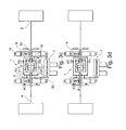
- FIGS. 3a-3d show a drive train 1 of a hybrid vehicle (reference numerals see primary Figure 3c ).
- the powertrain 1 a differential gear 2 with a differential carrier 3 and a left and a right output shaft 4 and 5, respectively.
- a planetary gear 6 and an internal combustion engine 7, a first electric machine 8 and a second electric machine 9 are provided.
- a sun gear 11 of the planetary gear 6 forms a first torque transmitting element of the planetary gear.
- a planetary carrier 13 connected to the first electric machine 8 forms a second torque-transmitting element of the planetary gear 6.
- a ring gear 14 forms a third torque-transmitting element of the planetary gear 6. The ring gear 14 is coupled to the second electric machine 9.
- a clutch K1 is provided.
- the planet carrier 13 or the first electric machine 8 connected thereto can be coupled to the sun gear 11 via the clutch K1.
- the clutch K1 By closing the clutch K1 thus the planetary gear 6 can be "blocked".
- a brake K2 is provided by means of which the ring gear 14 and the second electric machine 9 with respect to a vehicle-fixed component, such. B. a transmission housing 15, can be determined.
- the differential carrier 3 is coupled via a transmission gear 16 with the first torque transmitting element 11.
- the transmission gear 16 is formed by a plurality of "double planet", which are mounted on a planet carrier not shown here.
- Each of the double planets has a first planet gear 17, which meshes with the differential carrier 3 and the first torque transmission element 11, wherein the first planet gears 17 are arranged in the region between the differential carrier 3 and the first torque transmission element 11.
- a second planetary gear 18 is connected, which meshes with a vehicle or transmission-fixed shaft 19 with external teeth.
- the transmission gear 16 is not essential.
- the sun gear 11 which generally also referred to as the first torque transmitting element, be connected directly to the differential carrier 3.
- the internal combustion engine 7 via a translation, which is here formed by two gears 20, 21, coupled to the planet carrier 13, which in turn is rotatably connected to the armature of the first machine 8.
- FIGS. 3a-3d taken arrangement shown in detail.
- FIG. 3a shows the operating state "force balance".
- the clutch K1 and the brake K2 are open.
- the two electric machines 8, 9 are “turned on”.
- Switchched on means that they work as electric motors or as generators.
- the internal combustion engine can also be switched on. This operating condition is suitable for low vehicle speed ranges where high dynamics are needed, ie to accelerate the vehicle from a standstill or out of a low speed range.
- FIG. 3b shows an operating state in which the clutch K1 is closed and the brake K2 is open.
- the electric machines 8, 9 run here at one and the same speed.
- the internal combustion engine 7 may optionally be switched on.
- the performances of the two electric machines 8, 9 add up in this state.
- This operating condition is for a mean vehicle speed range of z. B. 50 - 150 km / h and offers in this speed range high dynamics.
- Figure 3c shows an operating state in which the clutch K1 is opened and the brake K2 is closed.
- the electric machine 8 operates in this operating state, whereas the electric machine 9 is switched off.
- the internal combustion engine 7 can optionally be switched on or off.
- This operating state is suitable for driving at substantially constant speed, with the electric machine 8 operating at a moderate speed of, for example, 1000-3000 rpm.
- FIG 3d figure shows the operating state "Parking”, in which the vehicle can be turned off.
- the clutch K1 and the brake K2 are closed and both electric motors 8, 9 are switched off.
Landscapes
- Engineering & Computer Science (AREA)
- Chemical & Material Sciences (AREA)
- Combustion & Propulsion (AREA)
- Transportation (AREA)
- Mechanical Engineering (AREA)
- Hybrid Electric Vehicles (AREA)
- Electric Propulsion And Braking For Vehicles (AREA)
- Arrangement Of Transmissions (AREA)
- Retarders (AREA)
Abstract
Description
- Die vorliegende Erfindung betrifft ein Hybridfahrzeug gemäß dem Oberbegriff des Patentanspruches 1.
- Bei den gegenwärtig am Markt erhältlichen Hybridfahrzeugen stellen Verbrennungsmotoren nach wie vor die Hauptantriebsquelle dar. Eine "Erweiterung" eines herkömmlichen Fahrzeugs mit Verbrennungsmotor um "Hybridkomponenten" führt zu einem relativ hohen Fahrzeuggewicht, was nicht unbedingt auf einen "ökologischen Verzicht" hindeutet. Vor allem die bei heutigen Hybridfahrzeugen eingesetzten "Hochvoltspeicher", die zur Versorgung des "Elektroantriebs" mit elektrischer Energie benötigt werden, stellen eine beträchtliche Zusatzmasse auf. Hochvoltspeicher sind nicht nur schwer, sondern auch teuer und machen aufgrund der hohen elektrischen Spannung spezielle Sicherheitsvorkehrungen im Fahrzeug erforderlich. Trotz des hohen Aufwands, der von vielen Herstellern bei der Elektrifizierung des Antriebsstrangs betrieben wird, können heutige Hybridfahrzeuge im rein elektrischen Fahrbetrieb nur vergleichsweise kurze Distanzen bei relativ niedrigen Geschwindigkeiten absolvieren.
- Aufgabe der Erfindung ist es, ein Hybridfahrzeug zu schaffen, das einen kompakt aufgebauten Antriebsstrang aufweist und das bei vergleichsweise geringer verbrennungsmotorischer Leistung eine hinreichend hohe Gesamtleistung und somit einen hohen Fahrkomfort bietet.
- Diese Aufgabe wird durch die Merkmale des Patentanspruches 1 gelöst. Vorteilhafte Ausgestaltungen und Weiterbildungen der Erfindung sind den Unteransprüchen zu entnehmen.
- Das Grundprinzip der Erfindung besteht darin, zwei elektrische Maschinen über ein Planetengetriebe mit einem Differentialgetriebe zu koppeln, wobei eine der beiden elektrischen Maschinen von einem "vergleichsweise kleinen" Verbrennungsmotor unterstützt werden kann.
- Das Hybridfahrzeug gemäß der Erfindung weist ein Differentialgetriebe mit einem als Getriebeeingang fungierenden Differentialkorb und zwei durch eine linke und eine rechte Abtriebswelle gebildete Getriebeausgänge auf. Ein erstes "Drehmomentübertragungselement" des Planetengetriebes ist mit dem Differentialkorb des Differentialgetriebes gekoppelt. Das erste "Drehmomentübertragungselement" kann z.B. durch eine Verzahnung des Differentialkorbs bzw. durch einen an den Differentialkorb angeflanschten Zahnring gebildet sein, die bzw. der als Sonnenrad des Planetengetriebes fungiert.
- Ein "zweites" Drehmomentübertragungselement des Planetengetriebes ist mit einer ersten der beiden elektrischen Maschinen gekoppelt. Das zweite Drehmomentübertragungselement des Planetengetriebes kann durch einen Planetenträger des Planetengetriebes gebildet sein. Auf dem Planetenträger sind mehrere mit dem ersten Drehmomentübertragungselement kämmende Planetenräder drehbar gelagert.
- Das dritte Drehmomentübertragungselement kann durch ein Hohlrad des Planetengetriebes gebildet sein.
- Aus den beiden über die beiden elektrischen Maschinen applizierten Drehzahlen ergibt sich die Drehzahl des Differentialkorbs, der als Getriebeeingang des Differentialgetriebes fungiert. Bei stehendem Fahrzeug müssen die elektrischen Maschinen nicht notwendigerweise die Drehzahl Null haben, sondern sie können z.B. gleichsinnig, d.h. in dieselbe Richtung aber mit entgegengesetzter Momentenrichtung drehen. Dies hat den Vorteil, dass die elektrischen Maschinen beim Anfahren des Fahrzeugs aus dem Stand nicht ihr jeweiliges "Losbrechmoment" überwinden müssen, wodurch sich übermäßig hohe Anfahrströme vermeiden lassen.
- Nach einer Weiterbildung der Erfindung ist die zweite elektrische Maschine über eine Kupplung mit dem Verbrennungsmotor koppelbar. Befindet sich die zweite elektrische Maschine im Antriebmodus, so kann bei geschlossener Kupplung der Verbrennungsmotor zum "Boosten" eingesetzt werden, d. h. als Antriebsunterstützung für die zweite elektrische Maschine. Arbeitet die zweite elektrische Maschine hingegen im generatorischen Betriebsmodus, so kann bei geschlossener Kupplung und laufendem Verbrennungsmotor verbrennungsmotorisch elektrische Energie generiert werden.
- Die oben beschriebene Anordnung ermöglicht sowohl bei einem Fahrzeug mit Frontantrieb als auch bei einem Fahrzeug mit Heckantrieb eine sehr kompakte Anordnung der einzelnen Komponenten. Die beiden elektrischen Maschinen sowie der Verbrennungsmotor und die Kupplung können in unmittelbarer Nähe des Differentialgetriebes angeordnet sein. Die Gehäusekomponenten der elektrischen Maschinen, des Hinterachsgetriebes und des Verbrennungsmotors können unmittelbar aneinander angeflanscht bzw. zu einer vormontierbaren Baugruppe miteinander verbunden sein.
- Ähnlich wie bei herkömmlichen Fahrzeugen kann in Bodenbereich der Karosserie ein sich in Längsrichtung des Hybridfahrzeugs erstreckender Mitteltunnel ausgebildet sein. Zumindest in einem Teil des durch den Mitteltunnel gebildeten Bauraums können "elektrische Energiespeicher", wie z. B. Batteriezellen bzw. Kondensatoren angeordnet sein, welche die elektrischen Maschinen mit elektrischer Energie versorgen bzw. generatorisch rekuperierte Energie zwischenspeichern.
- Die elektrischen Energiespeicher können in zwei "Stränge" bzw. "Gruppen" untergliedert sein, von denen jeder Strang bzw. jede Gruppe einer der beiden elektrischen Maschinen zugeordnet ist. Jeder der beiden Stränge bzw. jede der beiden Gruppen kann eine Nennspannung im Bereich zwischen 40 Volt und 400 Volt haben, z.B. 48 Volt. Bei derart niedrigen Spannungen ist im Unterschied zu den Hochvoltsystemen herkömmlicher Hybridfahrzeuge kein dezidierter Berührschutz erforderlich.
- Hinsichtlich der Leistungsverteilung kann z.B. vorgesehen sein, dass jede der beiden elektrischen Maschinen eine elektromotorische Leistung im Bereich zwischen 20 und 60 KW (z. B. jeweils von 20 KW) und der Verbrennungsmotor eine Antriebsleistung von ca. 20 KW erbringt. Der Verbrennungsmotor kann somit relativ kompakt und leicht sein. Denkbar ist z.B. an einen Ein-, Zwei-, oder Dreizylindermotor, wie er im Motorradbereich anzutreffen ist.
- Das Hybridfahrzeug kann ferner mit einer elektrischen Schnittstelle, z. B. einer "Steckdose" ausgestattet sein, die einen "Plug-In-Betrieb" ermöglicht. Über die elektrische Schnittstelle kann das Bordnetz bei stehendem Fahrzeug an das öffentliche Stromnetz angeschlossen werden, was ein Aufladen der elektrischen Energiespeicher ermöglicht.
- Im Folgenden wird die Erfindung im Zusammenhang mit der Zeichnung näher erläutert. Es zeigen:
- Figuren 1 und 2
- das Grundprinzip der Erfindung in schematischer Darstellung; und
- Figur 3a - 3d
- verschiedene Betriebszustände eines weiteren Ausführungsbeispiels der Erfindung.
-
Figur 1 zeigt in schematischer Darstellung den Antriebsstrang 1 eines Hybridfahrzeugs. Der Antriebsstrang 1 weist ein Differentialgetriebe 2 mit einem als Getriebeeingang fungierenden Differentialkorb 3 (vgl.Figur 2 ) sowie einer linken und einer rechten Abtriebswelle 4, 5 auf. Ferner ist ein Planetengetriebe 6 (vgl.Figur 2 ) vorgesehen, ein Verbrennungsmotor 7 sowie eine erste elektrische Maschine 8 und eine zweite elektrische Maschine 9, die über eine Kupplung 10 unmittelbar oder mittelbar über eine hier nicht näher dargestellte Drehschwingungsdämpfungseinrichtung mit der Kurbelwelle des Verbrennungsmotors 7 koppelbar ist. - Wie am besten aus
Figur 2 ersichtlich ist, weist der Differentialkorb 3 eine Verzahnung 11 auf, die als Sonnenrad des Planetengetriebes 6 fungiert. Mit der Verzahnung 11 kämmen mehrere in Umfangsrichtung der Verzahnung 11 angeordnete Planetenräder, von denen hier lediglich ein Planetenrad 12 dargestellt ist. Das Planetenrad 12 ist drehbar auf einem Planetenträger 13 angeordnet, der unmittelbar oder mittelbar über eine Übersetzungsstufe mit der elektrischen Maschine 8 drehgekoppelt ist. Der Planetenträger 13 kann somit von der elektrischen Maschine 8 angetrieben werden. Im generatorischen Betrieb ist es umgekehrt, d. h. der Planetenträger 13 treibt dann die elektrische Maschine 8 an. - Die Planetenräder 12 kämmen ferner mit einem Hohlrad 14, das unmittelbar oder mittelbar über eine hier nicht dargestellte Übersetzungsstufe mit der elektrischen Maschine 9 drehgekoppelt ist.
- Die
Figuren 3a - 3d zeigen einen Antriebsstrang 1 eines Hybridfahrzeugs (Bezugszeichen siehe primärFigur 3c ). Entsprechend dem Ausführungsbeispiel derFigur 2 weist der Antriebsstrang 1 ein Differentialgetriebe 2 mit einem Differentialkorb 3 sowie einer linken und einer rechten Abtriebswelle 4 bzw. 5 auf. Ferner ist ein Planetengetriebe 6 sowie ein Verbrennungsmotor 7, eine erste elektrische Maschine 8 und eine zweite elektrische Maschine 9 vorgesehen. - Ein Sonnenrad 11 des Planetengetriebes 6 bildet ein erstes Drehmomentübertragungselement des Planetengetriebes. Ein mit der ersten elektrischen Maschine 8 verbundener Planetenträger 13 bildet ein zweites Drehmomentübertragungselement des Planetengetriebes 6. Ein Hohlrad 14 bildet ein drittes Drehmomentübertragungselement des Planetengetriebes 6. Das Hohlrad 14 ist mit der zweiten elektrischen Maschine 9 gekoppelt.
- Ferner ist eine Kupplung K1 vorgesehen. Über die Kupplung K1 kann der Planetenträger 13 bzw. die damit verbundene erste elektrische Maschine 8 mit dem Sonnenrad 11 gekoppelt werden. Durch Schließen der Kupplung K1 kann somit das Planetengetriebe 6 "verblockt" werden.
- Ferner ist eine Bremse K2 vorgesehen, mittels der das Hohlrad 14 bzw. die zweite elektrische Maschine 9 in Bezug auf ein fahrzeugfestes Bauteil, wie z. B. ein Getriebegehäuse 15, festgestellt werden kann.
- Wie aus den
Figuren 3a - 3 d ersichtlich ist, ist der Differentialkorb 3 über ein Übersetzungsgetriebe 16 mit dem ersten Drehmomentübertragungselement 11 gekoppelt. Das Übersetzungsgetriebe 16 ist durch mehrere "Doppelplaneten", die auf einem hier nicht näher dargestellten Planetenträger gelagert sind, gebildet. Jeder der Doppelplaneten weist ein erstes Planetenrad 17 auf, welches mit dem Differentialkorb 3 und dem ersten Drehmomentübertragungselement 11 kämmt, wobei die ersten Planetenräder 17 im Bereich zwischen dem Differentialkorb 3 und dem ersten Drehmomentübertragungselement 11 angeordnet sind. Drehfest mit dem ersten Planetenrad 17 eines jeden Doppelplaneten ist ein zweites Planetenrad 18 verbunden, das mit einer fahrzeug- bzw. getriebefeststehenden Welle 19 mit Außenverzahnung kämmt. - Es sei ausdrücklich erwähnt, dass das Übersetzungsgetriebe 16 nicht unbedingt erforderlich ist. Alternativ dazu könnte das Sonnenrad 11, welches verallgemeinert auch als erstes Drehmomentübertragungselement bezeichnet wurde, auch direkt mit dem Differentialkorb 3 verbunden sein.
- Vollständigkeitshalber sei noch erwähnt, dass der Verbrennungsmotor 7 über eine Übersetzung, die hier durch zwei Zahnräder 20, 21 gebildet ist, mit dem Planetenträger 13 gekoppelt ist, welcher wiederum drehfest mit dem Anker der ersten Maschine 8 verbunden ist.
- Im Folgenden wird auf einzelne Betriebszustände, welche die in
Figuren 3a - 3d gezeigte Anordnung einnehmen kann, näher eingegangen. -
Figur 3a zeigt den Betriebszustand "Kraftwaage". Hier sind die Kupplung K1 und die Bremse K2 geöffnet. Die beiden elektrischen Maschinen 8, 9 sind "eingeschaltet". "Eingeschaltet" bedeutet, dass sie als Elektromotoren bzw. als Generatoren arbeiten. Der Verbrennungsmotor kann zusätzlich eingeschaltet werden. Dieser Betriebszustand ist für niedrige Fahrzeuggeschwindigkeitsbereiche geeignet, in denen eine hohe Dynamik benötigt wird, d. h. zum Beschleunigen des Fahrzeugs aus dem Stand bzw. aus einem niedrigen Geschwindigkeitsbereich heraus. - Wichtig zu erwähnen ist, dass mit der in den
Figuren 3a - 3d gezeigten Anordnung ein Anfahren aus dem Stand heraus möglich ist, ohne dass die elektrischen Maschinen von der Drehzahl Null weg beschleunigt werden müssen, was eine sehr kostengünstige Auslegung und Gestaltung der elektrischen Maschinen ermöglicht. Die elektrischen Maschinen können vielmehr bereits eine gewisse Drehzahl haben, wobei sie zum Anfahren des Fahrzeugs in dieselbe Richtung aber mit entgegengesetzter Momentenrichtung drehen können. -
Figur 3b zeigt einen Betriebszustand, bei dem die Kupplung K1 geschlossen und die Bremse K2 offen ist. Die elektrischen Maschinen 8, 9 laufen hier mit ein- und derselben Drehzahl. Der Verbrennungsmotor 7 kann gegebenenfalls zugeschaltet sein. Die Leistungen der beiden elektrischen Maschinen 8, 9 addieren sich in diesem Zustand. Dieser Betriebszustand ist für einen mittleren Fahrzeuggeschwindigkeitsbereich von z. B. 50 - 150 km/h geeignet und bietet in diesem Drehzahlbereich eine hohe Dynamik. -
Figur 3c zeigt einen Betriebszustand, bei dem die Kupplung K1geöffnet und die Bremse K2 geschlossen ist. Die elektrische Maschine 8 arbeitet in diesem Betriebszustand, wohingegen die elektrische Maschine 9 ausgeschaltet ist. Der Verbrennungsmotor 7 kann wahlweise zu- oder abgeschaltet sein. Dieser Betriebszustand ist für Fahrten mit im Wesentlichen konstanter Geschwindigkeit geeignet, wobei die elektrische Maschine 8 mit einer moderaten Drehzahl von z.B. 1000 - 3000 U/min arbeitet. -
Figur 3d zeigt den Betriebszustand "Parken", in dem das Fahrzeug abgestellt werden kann. Im Betriebszustand "Parken" ist die Kupplung K1 und die Bremse K2 jeweils geschlossen und beide Elektromotoren 8, 9 sind ausgeschaltet.
Claims (19)
- Hybridfahrzeug mit- einem Differentialgetriebe (2), das einen als Getriebeeingang fungierenden Differentialkorb (3) sowie zwei durch eine linke und eine rechte Abtriebswelle (4, 5) gebildete Getriebeausgänge aufweist,- einem Planetengetriebe (6),- einem Verbrennungsmotor (7) und- einer ersten und einer zweiten elektrischen Maschine (8, 9),
dadurch gekennzeichnet, dass- ein erstes Drehmomentübertragungselement (11) des Planetengetriebes (6) mit dem Differentialkorb (3),- ein zweites Drehmomentübertragungselement (13) des Planetengetriebes (6) mit der der ersten elektrischen Maschine (8) und- ein drittes Drehmomentübertragungselement (14) des Planetengetriebes (6) mit der zweiten elektrischen Maschine (9) drehgekoppelt ist. - Hybridfahrzeug nach Anspruch 1, dadurch gekennzeichnet, dass das erste Drehmomentübertragungselement (1) durch eine Verzahnung des Differentialkorbs (3) bzw. durch eine mit dem Differentialkorb (3) verbundene Verzahnung gebildet ist und als Sonnenrad des Planetengetriebes (6) fungiert.
- Hybridfahrzeug nach Anspruch 1 oder 2, dadurch gekennzeichnet, dass das zweite Drehmomentübertragungselement (13) durch einen Planetenträger des Planetengetriebes (6) gebildet ist.
- Hybridfahrzeug nach einem der Ansprüche 1 bis 3, dadurch gekennzeichnet, dass das dritte Drehmomentübertragungselement (14) durch ein Hohlrad des Planetengetriebes (6) gebildet ist.
- Hybridfahrzeug nach einem der Ansprüche 1 bis 4, dadurch gekennzeichnet, dass die zweite elektrische Maschine (9) über eine Kupplung (10) mit dem Verbrennungsmotor (7) koppelbar ist.
- Hybridfahrzeug nach einem der Ansprüche 1 bis 5, dadurch gekennzeichnet, dass das Differentialgetriebe (2) ein Hinterachsgetriebe des Hybridfahrzeugs ist.
- Hybridfahrzeug nach einem der Ansprüche 1 bis 6, dadurch gekennzeichnet, dass die beiden elektrischen Maschinen (8, 9) in unmittelbarer Nähe des Differentialgetriebes (2) angeordnet sind.
- Hybridfahrzeug nach einem der Ansprüche 1 bis 7, dadurch gekennzeichnet, dass der Verbrennungsmotor (7) und die Kupplung (10) in unmittelbarer Nähe des Differentialgetriebes (2) angeordnet sind.
- Hybridfahrzeug nach einem der Ansprüche 1 bis 8, dadurch gekennzeichnet, dass im Fahrzeugboden ein sich in Längsrichtung des Hybridfahrzeugs erstreckender Mitteltunnel vorgesehen ist.
- Hybridfahrzeug nach Anspruch 9, dadurch gekennzeichnet, dass zumindest in einem Teil des durch den Mitteltunnel gebildeten Bauraums elektrische Energiespeicher angeordnet sind, welche zur Versorgung der elektrischen Maschinen (8, 9) mit elektrischer Energie vorgesehen sind.
- Hybridfahrzeug nach Anspruch 10, dadurch gekennzeichnet, dass die elektrischen Energiespeicher durch Batterien und/oder durch Kondensatoren gebildet sind.
- Hybridfahrzeug nach einem der Ansprüche 10 oder 11, dadurch gekennzeichnet, dass mindestens ein erster, der ersten elektrischen Maschine (8) zugeordneter Energiespeicher und mindestens ein zweiter, der zweiten elektrischen Maschine (9) zugeordneter Energiespeicher vorgesehen ist.
- Hybridfahrzeug nach einem der Ansprüche 10 bis 12, dadurch gekennzeichnet, dass eine mit den elektrischen Energiespeichern verbundene elektrische Schnittstelle vorgesehen ist, über welche die elektrischen Energiespeicher bei stehendem Fahrzeug an ein externes Stromnetz angeschlossen werden können.
- Hybridfahrzeug nach einem der Ansprüche 1 bis 13, dadurch gekennzeichnet, dass die elektrischen Maschinen jeweils eine Leistung von weniger als 50 KW, insbesondere von weniger als jeweils 25 KW aufweisen.
- Hybridfahrzeug nach einem der vorausgehenden Ansprüche, dadurch gekennzeichnet, dass eine Kurbelwelle des Verbrennungsmotors (7) über eine Übersetzungsstufe (20, 21), insbesondere über eine Zahnradstufe, mit dem zweiten Drehmomentübertragungselement (13) gekoppelt ist.
- Hybridfahrzeug nach einem der vorausgehenden Ansprüche, dadurch gekennzeichnet, dass eine Kupplung (K1) vorgesehen ist, über welche die erste elektrische Maschine 8 bzw. dass damit gekoppelte zweite Drehmomentübertragungselement (13) mit dem ersten Drehmomentübertragungselement (11) koppelbar ist.
- Hybridfahrzeug nach einem der vorausgehenden Ansprüche, dadurch gekennzeichnet, dass eine Bremse (K2) vorgesehen ist, mittels der das dritte Drehmomentübertragungselement (14) in Bezug auf ein fahrzeugfestes Bauteil, insbesondere in Bezug auf ein Getriebegehäuse (15) festgestellt werden kann.
- Hybridfahrzeug nach einem der vorausgehenden Ansprüche, dadurch gekennzeichnet, dass das erste Drehmomentübertragungselement (11) über eine Übersetzung (16) permanent mit dem Differentialkorb (3) gekoppelt ist.
- Hybridfahrzeug nach einem der Ansprüche 1 bis 18, dadurch gekennzeichnet, dass das erste Drehmomentübertragungselement (11) unmittelbar mit dem Differentialkorb (3) drehgekoppelt ist.
Applications Claiming Priority (1)
| Application Number | Priority Date | Filing Date | Title |
|---|---|---|---|
| DE102009008484A DE102009008484A1 (de) | 2009-02-11 | 2009-02-11 | Hybridantrieb |
Publications (2)
| Publication Number | Publication Date |
|---|---|
| EP2218603A1 true EP2218603A1 (de) | 2010-08-18 |
| EP2218603B1 EP2218603B1 (de) | 2011-08-24 |
Family
ID=42112121
Family Applications (1)
| Application Number | Title | Priority Date | Filing Date |
|---|---|---|---|
| EP10001246A Not-in-force EP2218603B1 (de) | 2009-02-11 | 2010-02-06 | Hybridantrieb |
Country Status (3)
| Country | Link |
|---|---|
| EP (1) | EP2218603B1 (de) |
| AT (1) | ATE521496T1 (de) |
| DE (1) | DE102009008484A1 (de) |
Cited By (8)
| Publication number | Priority date | Publication date | Assignee | Title |
|---|---|---|---|---|
| WO2014029651A1 (de) | 2012-08-24 | 2014-02-27 | Avl List Gmbh | Antriebsstrang für ein fahrzeug |
| EP3326852A1 (de) * | 2016-11-24 | 2018-05-30 | Audi Ag | Motorsteuerung von fahrzeugen mit mehreren e-maschinen |
| DE102017208141A1 (de) * | 2017-05-15 | 2018-11-15 | Magna powertrain gmbh & co kg | Fahrzeug mit einem Antriebsstrang und Verfahren zur Auslegung eines solchen |
| DE102017208138A1 (de) * | 2017-05-15 | 2018-11-15 | Magna powertrain gmbh & co kg | Hybrid-Fahrzeug mit einem Antriebsstrang und Verfahren zur Auslegung eines solchen |
| WO2019110285A1 (de) * | 2017-12-04 | 2019-06-13 | Bayerische Motoren Werke Aktiengesellschaft | Hybridantriebsstrang |
| CN111486213A (zh) * | 2020-04-07 | 2020-08-04 | 刘润龙 | 一种结合差速装置的力矩耦合器 |
| CN113173065A (zh) * | 2021-06-07 | 2021-07-27 | 深圳臻宇新能源动力科技有限公司 | 双电机驱动系统及电动汽车 |
| CN116461317A (zh) * | 2023-04-27 | 2023-07-21 | 重庆隆鑫新能源科技有限公司 | 一种车辆及其混合动力系统 |
Citations (2)
| Publication number | Priority date | Publication date | Assignee | Title |
|---|---|---|---|---|
| EP1375226A2 (de) * | 2002-05-31 | 2004-01-02 | Nissan Motor Co., Ltd. | Hybrid transmission |
| US20060009323A1 (en) * | 2004-07-10 | 2006-01-12 | Lingling Zhang | Hybrid electric vehicle |
-
2009
- 2009-02-11 DE DE102009008484A patent/DE102009008484A1/de not_active Withdrawn
-
2010
- 2010-02-06 EP EP10001246A patent/EP2218603B1/de not_active Not-in-force
- 2010-02-06 AT AT10001246T patent/ATE521496T1/de active
Patent Citations (2)
| Publication number | Priority date | Publication date | Assignee | Title |
|---|---|---|---|---|
| EP1375226A2 (de) * | 2002-05-31 | 2004-01-02 | Nissan Motor Co., Ltd. | Hybrid transmission |
| US20060009323A1 (en) * | 2004-07-10 | 2006-01-12 | Lingling Zhang | Hybrid electric vehicle |
Cited By (11)
| Publication number | Priority date | Publication date | Assignee | Title |
|---|---|---|---|---|
| WO2014029651A1 (de) | 2012-08-24 | 2014-02-27 | Avl List Gmbh | Antriebsstrang für ein fahrzeug |
| EP3326852A1 (de) * | 2016-11-24 | 2018-05-30 | Audi Ag | Motorsteuerung von fahrzeugen mit mehreren e-maschinen |
| US11072322B2 (en) | 2016-11-24 | 2021-07-27 | Audi Ag | Engine control of motor vehicles with a plurality of e-machines |
| DE102017208141A1 (de) * | 2017-05-15 | 2018-11-15 | Magna powertrain gmbh & co kg | Fahrzeug mit einem Antriebsstrang und Verfahren zur Auslegung eines solchen |
| DE102017208138A1 (de) * | 2017-05-15 | 2018-11-15 | Magna powertrain gmbh & co kg | Hybrid-Fahrzeug mit einem Antriebsstrang und Verfahren zur Auslegung eines solchen |
| WO2019110285A1 (de) * | 2017-12-04 | 2019-06-13 | Bayerische Motoren Werke Aktiengesellschaft | Hybridantriebsstrang |
| CN111183053A (zh) * | 2017-12-04 | 2020-05-19 | 宝马股份公司 | 混合动力传动系 |
| US11518233B2 (en) | 2017-12-04 | 2022-12-06 | Bayerische Motoren Werke Aktiengesellschaft | Hybrid drive train |
| CN111486213A (zh) * | 2020-04-07 | 2020-08-04 | 刘润龙 | 一种结合差速装置的力矩耦合器 |
| CN113173065A (zh) * | 2021-06-07 | 2021-07-27 | 深圳臻宇新能源动力科技有限公司 | 双电机驱动系统及电动汽车 |
| CN116461317A (zh) * | 2023-04-27 | 2023-07-21 | 重庆隆鑫新能源科技有限公司 | 一种车辆及其混合动力系统 |
Also Published As
| Publication number | Publication date |
|---|---|
| ATE521496T1 (de) | 2011-09-15 |
| DE102009008484A1 (de) | 2010-08-12 |
| EP2218603B1 (de) | 2011-08-24 |
Similar Documents
| Publication | Publication Date | Title |
|---|---|---|
| DE102016120965B4 (de) | Antriebsstrang mit modularer Antriebseinheit | |
| DE102014118234B4 (de) | Leistungsübertragungssystem eines Hybridelektrofahrzeugs | |
| EP2370285B1 (de) | Hybrid-antriebseinheit und verfahren zu deren betrieb | |
| DE102010036235B4 (de) | Nebenaggregatantriebssystem mit variabler Drehzahl | |
| EP2218603B1 (de) | Hybridantrieb | |
| DE102019214202B4 (de) | Antriebsanordnung für eine Zugmaschine | |
| DE102010036321B4 (de) | Antriebssystem für ein Hybridfahrzeug und Hybridfahrzeug mit einem derartigen Antriebssystem | |
| AT513352B1 (de) | Antriebsstrang für ein Fahrzeug | |
| EP2289751B1 (de) | Hybridantriebsstrang für ein Kraftfahrzeug und Verfahren zu dessen Betrieb | |
| DE102014118199B4 (de) | Leistungsübertragungssystem eines Hybridelektrofahrzeugs | |
| DE102008030581A1 (de) | Triebstrang für ein Kraftfahrzeug und Verfahren zum Betreiben eines Triebstrangs eines Kraftfahrzeuges | |
| DE102006002839A1 (de) | Hybridfahrzeug | |
| DE102012219733A1 (de) | Planetenkoppelgetriebe | |
| DE102010017760A1 (de) | Antriebssystem für ein Kraftfahrzeug und Kraftfahrzeug mit einem derartigen Antriebssystem | |
| DE102020123116A1 (de) | Antriebseinheit und Antriebsanordnung | |
| DE102020105843A1 (de) | Antriebseinrichtung für ein Kraftfahrzeug | |
| DE102014222359A1 (de) | Hybridantriebssystem | |
| DE102008061945A1 (de) | Elektrische Achsantriebseinheit mit variabler Momentenverteilung | |
| DE102009050956A1 (de) | Antriebsstrang für ein Hybridfahrzeug | |
| DE102014221600B3 (de) | Getriebestruktur für einen Hybridantrieb eines Kraftfahrzeuges und Hybridantrieb | |
| DE102010038086A1 (de) | Antriebssystem für ein Kraftfahrzeug, Verfahren zum Betreiben eines derartigen Antriebssystems und Kraftfahrzeug mit einem derartigen Antriebssystem | |
| DE102007056302A1 (de) | Hybridfahrzeug | |
| DE102008044035B4 (de) | Allrad-Hybridantriebsstrang für ein Kraftfahrzeug und Verfahren zum Betreiben des Hybridantriebsstrangs | |
| DE102013222724A1 (de) | Antriebsstrang für ein Fahrzeug sowie Fahrzeug mit dem Antriebsstrang | |
| DE102013222721A1 (de) | Antriebsstrang für ein Fahrzeug sowie Fahrzeug mit dem Antriebsstrang |
Legal Events
| Date | Code | Title | Description |
|---|---|---|---|
| PUAI | Public reference made under article 153(3) epc to a published international application that has entered the european phase |
Free format text: ORIGINAL CODE: 0009012 |
|
| AK | Designated contracting states |
Kind code of ref document: A1 Designated state(s): AT BE BG CH CY CZ DE DK EE ES FI FR GB GR HR HU IE IS IT LI LT LU LV MC MK MT NL NO PL PT RO SE SI SK SM TR |
|
| AX | Request for extension of the european patent |
Extension state: AL BA RS |
|
| 17P | Request for examination filed |
Effective date: 20100909 |
|
| GRAP | Despatch of communication of intention to grant a patent |
Free format text: ORIGINAL CODE: EPIDOSNIGR1 |
|
| RIC1 | Information provided on ipc code assigned before grant |
Ipc: B60K 6/40 20071001ALI20110222BHEP Ipc: B60K 6/445 20071001AFI20110222BHEP Ipc: B60K 1/04 20060101ALI20110222BHEP Ipc: B60K 6/365 20071001ALI20110222BHEP Ipc: B60K 6/387 20071001ALI20110222BHEP |
|
| GRAS | Grant fee paid |
Free format text: ORIGINAL CODE: EPIDOSNIGR3 |
|
| GRAA | (expected) grant |
Free format text: ORIGINAL CODE: 0009210 |
|
| AK | Designated contracting states |
Kind code of ref document: B1 Designated state(s): AT BE BG CH CY CZ DE DK EE ES FI FR GB GR HR HU IE IS IT LI LT LU LV MC MK MT NL NO PL PT RO SE SI SK SM TR |
|
| REG | Reference to a national code |
Ref country code: GB Ref legal event code: FG4D Free format text: NOT ENGLISH |
|
| REG | Reference to a national code |
Ref country code: CH Ref legal event code: EP |
|
| REG | Reference to a national code |
Ref country code: IE Ref legal event code: FG4D Free format text: LANGUAGE OF EP DOCUMENT: GERMAN |
|
| REG | Reference to a national code |
Ref country code: DE Ref legal event code: R096 Ref document number: 502010000072 Country of ref document: DE Effective date: 20111027 |
|
| REG | Reference to a national code |
Ref country code: NL Ref legal event code: VDEP Effective date: 20110824 |
|
| LTIE | Lt: invalidation of european patent or patent extension |
Effective date: 20110824 |
|
| PG25 | Lapsed in a contracting state [announced via postgrant information from national office to epo] |
Ref country code: NL Free format text: LAPSE BECAUSE OF FAILURE TO SUBMIT A TRANSLATION OF THE DESCRIPTION OR TO PAY THE FEE WITHIN THE PRESCRIBED TIME-LIMIT Effective date: 20110824 Ref country code: SE Free format text: LAPSE BECAUSE OF FAILURE TO SUBMIT A TRANSLATION OF THE DESCRIPTION OR TO PAY THE FEE WITHIN THE PRESCRIBED TIME-LIMIT Effective date: 20110824 Ref country code: LT Free format text: LAPSE BECAUSE OF FAILURE TO SUBMIT A TRANSLATION OF THE DESCRIPTION OR TO PAY THE FEE WITHIN THE PRESCRIBED TIME-LIMIT Effective date: 20110824 Ref country code: HR Free format text: LAPSE BECAUSE OF FAILURE TO SUBMIT A TRANSLATION OF THE DESCRIPTION OR TO PAY THE FEE WITHIN THE PRESCRIBED TIME-LIMIT Effective date: 20110824 Ref country code: IS Free format text: LAPSE BECAUSE OF FAILURE TO SUBMIT A TRANSLATION OF THE DESCRIPTION OR TO PAY THE FEE WITHIN THE PRESCRIBED TIME-LIMIT Effective date: 20111224 Ref country code: FI Free format text: LAPSE BECAUSE OF FAILURE TO SUBMIT A TRANSLATION OF THE DESCRIPTION OR TO PAY THE FEE WITHIN THE PRESCRIBED TIME-LIMIT Effective date: 20110824 Ref country code: PT Free format text: LAPSE BECAUSE OF FAILURE TO SUBMIT A TRANSLATION OF THE DESCRIPTION OR TO PAY THE FEE WITHIN THE PRESCRIBED TIME-LIMIT Effective date: 20111226 Ref country code: NO Free format text: LAPSE BECAUSE OF FAILURE TO SUBMIT A TRANSLATION OF THE DESCRIPTION OR TO PAY THE FEE WITHIN THE PRESCRIBED TIME-LIMIT Effective date: 20111124 |
|
| PG25 | Lapsed in a contracting state [announced via postgrant information from national office to epo] |
Ref country code: GR Free format text: LAPSE BECAUSE OF FAILURE TO SUBMIT A TRANSLATION OF THE DESCRIPTION OR TO PAY THE FEE WITHIN THE PRESCRIBED TIME-LIMIT Effective date: 20111125 Ref country code: LV Free format text: LAPSE BECAUSE OF FAILURE TO SUBMIT A TRANSLATION OF THE DESCRIPTION OR TO PAY THE FEE WITHIN THE PRESCRIBED TIME-LIMIT Effective date: 20110824 Ref country code: PL Free format text: LAPSE BECAUSE OF FAILURE TO SUBMIT A TRANSLATION OF THE DESCRIPTION OR TO PAY THE FEE WITHIN THE PRESCRIBED TIME-LIMIT Effective date: 20110824 Ref country code: CY Free format text: LAPSE BECAUSE OF FAILURE TO SUBMIT A TRANSLATION OF THE DESCRIPTION OR TO PAY THE FEE WITHIN THE PRESCRIBED TIME-LIMIT Effective date: 20110824 Ref country code: SI Free format text: LAPSE BECAUSE OF FAILURE TO SUBMIT A TRANSLATION OF THE DESCRIPTION OR TO PAY THE FEE WITHIN THE PRESCRIBED TIME-LIMIT Effective date: 20110824 |
|
| REG | Reference to a national code |
Ref country code: IE Ref legal event code: FD4D |
|
| PG25 | Lapsed in a contracting state [announced via postgrant information from national office to epo] |
Ref country code: SK Free format text: LAPSE BECAUSE OF FAILURE TO SUBMIT A TRANSLATION OF THE DESCRIPTION OR TO PAY THE FEE WITHIN THE PRESCRIBED TIME-LIMIT Effective date: 20110824 Ref country code: IE Free format text: LAPSE BECAUSE OF FAILURE TO SUBMIT A TRANSLATION OF THE DESCRIPTION OR TO PAY THE FEE WITHIN THE PRESCRIBED TIME-LIMIT Effective date: 20110824 Ref country code: CZ Free format text: LAPSE BECAUSE OF FAILURE TO SUBMIT A TRANSLATION OF THE DESCRIPTION OR TO PAY THE FEE WITHIN THE PRESCRIBED TIME-LIMIT Effective date: 20110824 |
|
| PG25 | Lapsed in a contracting state [announced via postgrant information from national office to epo] |
Ref country code: RO Free format text: LAPSE BECAUSE OF FAILURE TO SUBMIT A TRANSLATION OF THE DESCRIPTION OR TO PAY THE FEE WITHIN THE PRESCRIBED TIME-LIMIT Effective date: 20110824 Ref country code: EE Free format text: LAPSE BECAUSE OF FAILURE TO SUBMIT A TRANSLATION OF THE DESCRIPTION OR TO PAY THE FEE WITHIN THE PRESCRIBED TIME-LIMIT Effective date: 20110824 |
|
| PG25 | Lapsed in a contracting state [announced via postgrant information from national office to epo] |
Ref country code: DK Free format text: LAPSE BECAUSE OF FAILURE TO SUBMIT A TRANSLATION OF THE DESCRIPTION OR TO PAY THE FEE WITHIN THE PRESCRIBED TIME-LIMIT Effective date: 20110824 |
|
| PLBE | No opposition filed within time limit |
Free format text: ORIGINAL CODE: 0009261 |
|
| STAA | Information on the status of an ep patent application or granted ep patent |
Free format text: STATUS: NO OPPOSITION FILED WITHIN TIME LIMIT |
|
| 26N | No opposition filed |
Effective date: 20120525 |
|
| BERE | Be: lapsed |
Owner name: BAYERISCHE MOTOREN WERKE Effective date: 20120228 |
|
| REG | Reference to a national code |
Ref country code: DE Ref legal event code: R097 Ref document number: 502010000072 Country of ref document: DE Effective date: 20120525 |
|
| PG25 | Lapsed in a contracting state [announced via postgrant information from national office to epo] |
Ref country code: MC Free format text: LAPSE BECAUSE OF NON-PAYMENT OF DUE FEES Effective date: 20120229 |
|
| PG25 | Lapsed in a contracting state [announced via postgrant information from national office to epo] |
Ref country code: BE Free format text: LAPSE BECAUSE OF NON-PAYMENT OF DUE FEES Effective date: 20120228 |
|
| PG25 | Lapsed in a contracting state [announced via postgrant information from national office to epo] |
Ref country code: MK Free format text: LAPSE BECAUSE OF FAILURE TO SUBMIT A TRANSLATION OF THE DESCRIPTION OR TO PAY THE FEE WITHIN THE PRESCRIBED TIME-LIMIT Effective date: 20110824 |
|
| PG25 | Lapsed in a contracting state [announced via postgrant information from national office to epo] |
Ref country code: ES Free format text: LAPSE BECAUSE OF FAILURE TO SUBMIT A TRANSLATION OF THE DESCRIPTION OR TO PAY THE FEE WITHIN THE PRESCRIBED TIME-LIMIT Effective date: 20111205 |
|
| PG25 | Lapsed in a contracting state [announced via postgrant information from national office to epo] |
Ref country code: BG Free format text: LAPSE BECAUSE OF FAILURE TO SUBMIT A TRANSLATION OF THE DESCRIPTION OR TO PAY THE FEE WITHIN THE PRESCRIBED TIME-LIMIT Effective date: 20111124 |
|
| PG25 | Lapsed in a contracting state [announced via postgrant information from national office to epo] |
Ref country code: MT Free format text: LAPSE BECAUSE OF FAILURE TO SUBMIT A TRANSLATION OF THE DESCRIPTION OR TO PAY THE FEE WITHIN THE PRESCRIBED TIME-LIMIT Effective date: 20110824 |
|
| PG25 | Lapsed in a contracting state [announced via postgrant information from national office to epo] |
Ref country code: TR Free format text: LAPSE BECAUSE OF FAILURE TO SUBMIT A TRANSLATION OF THE DESCRIPTION OR TO PAY THE FEE WITHIN THE PRESCRIBED TIME-LIMIT Effective date: 20110824 |
|
| PG25 | Lapsed in a contracting state [announced via postgrant information from national office to epo] |
Ref country code: LU Free format text: LAPSE BECAUSE OF NON-PAYMENT OF DUE FEES Effective date: 20120206 Ref country code: SM Free format text: LAPSE BECAUSE OF FAILURE TO SUBMIT A TRANSLATION OF THE DESCRIPTION OR TO PAY THE FEE WITHIN THE PRESCRIBED TIME-LIMIT Effective date: 20110824 |
|
| PG25 | Lapsed in a contracting state [announced via postgrant information from national office to epo] |
Ref country code: HU Free format text: LAPSE BECAUSE OF FAILURE TO SUBMIT A TRANSLATION OF THE DESCRIPTION OR TO PAY THE FEE WITHIN THE PRESCRIBED TIME-LIMIT Effective date: 20100206 |
|
| REG | Reference to a national code |
Ref country code: CH Ref legal event code: PL |
|
| PG25 | Lapsed in a contracting state [announced via postgrant information from national office to epo] |
Ref country code: LI Free format text: LAPSE BECAUSE OF NON-PAYMENT OF DUE FEES Effective date: 20140228 Ref country code: CH Free format text: LAPSE BECAUSE OF NON-PAYMENT OF DUE FEES Effective date: 20140228 |
|
| REG | Reference to a national code |
Ref country code: FR Ref legal event code: PLFP Year of fee payment: 7 |
|
| REG | Reference to a national code |
Ref country code: AT Ref legal event code: MM01 Ref document number: 521496 Country of ref document: AT Kind code of ref document: T Effective date: 20150206 |
|
| PG25 | Lapsed in a contracting state [announced via postgrant information from national office to epo] |
Ref country code: AT Free format text: LAPSE BECAUSE OF NON-PAYMENT OF DUE FEES Effective date: 20150206 |
|
| REG | Reference to a national code |
Ref country code: FR Ref legal event code: PLFP Year of fee payment: 8 |
|
| REG | Reference to a national code |
Ref country code: FR Ref legal event code: PLFP Year of fee payment: 9 |
|
| PGFP | Annual fee paid to national office [announced via postgrant information from national office to epo] |
Ref country code: IT Payment date: 20190222 Year of fee payment: 10 Ref country code: DE Payment date: 20190215 Year of fee payment: 10 Ref country code: GB Payment date: 20190221 Year of fee payment: 10 |
|
| PGFP | Annual fee paid to national office [announced via postgrant information from national office to epo] |
Ref country code: FR Payment date: 20190221 Year of fee payment: 10 |
|
| REG | Reference to a national code |
Ref country code: DE Ref legal event code: R119 Ref document number: 502010000072 Country of ref document: DE |
|
| GBPC | Gb: european patent ceased through non-payment of renewal fee |
Effective date: 20200206 |
|
| PG25 | Lapsed in a contracting state [announced via postgrant information from national office to epo] |
Ref country code: GB Free format text: LAPSE BECAUSE OF NON-PAYMENT OF DUE FEES Effective date: 20200206 Ref country code: DE Free format text: LAPSE BECAUSE OF NON-PAYMENT OF DUE FEES Effective date: 20200901 Ref country code: FR Free format text: LAPSE BECAUSE OF NON-PAYMENT OF DUE FEES Effective date: 20200229 |
|
| PG25 | Lapsed in a contracting state [announced via postgrant information from national office to epo] |
Ref country code: IT Free format text: LAPSE BECAUSE OF NON-PAYMENT OF DUE FEES Effective date: 20200206 |
|
| P01 | Opt-out of the competence of the unified patent court (upc) registered |
Effective date: 20230502 |