EP2218648A2 - Procédé et dispositif destinés à l'étiquetage de récipients - Google Patents
Procédé et dispositif destinés à l'étiquetage de récipients Download PDFInfo
- Publication number
- EP2218648A2 EP2218648A2 EP10151891A EP10151891A EP2218648A2 EP 2218648 A2 EP2218648 A2 EP 2218648A2 EP 10151891 A EP10151891 A EP 10151891A EP 10151891 A EP10151891 A EP 10151891A EP 2218648 A2 EP2218648 A2 EP 2218648A2
- Authority
- EP
- European Patent Office
- Prior art keywords
- centering
- container
- containers
- bell
- centering bell
- Prior art date
- Legal status (The legal status is an assumption and is not a legal conclusion. Google has not performed a legal analysis and makes no representation as to the accuracy of the status listed.)
- Granted
Links
Images



Classifications
-
- B—PERFORMING OPERATIONS; TRANSPORTING
- B65—CONVEYING; PACKING; STORING; HANDLING THIN OR FILAMENTARY MATERIAL
- B65C—LABELLING OR TAGGING MACHINES, APPARATUS, OR PROCESSES
- B65C9/00—Details of labelling machines or apparatus
- B65C9/02—Devices for moving articles, e.g. containers, past labelling station
-
- B—PERFORMING OPERATIONS; TRANSPORTING
- B65—CONVEYING; PACKING; STORING; HANDLING THIN OR FILAMENTARY MATERIAL
- B65C—LABELLING OR TAGGING MACHINES, APPARATUS, OR PROCESSES
- B65C3/00—Labelling other than flat surfaces
- B65C3/26—Affixing labels to non-rigid containers, e.g. bottles made of polyethylene or boxes to be inflated by internal air pressure prior to labelling
Definitions
- the invention relates to a device for labeling containers with an overhead opening, in particular of thin-walled bottles.
- the device has at least one centering unit for fixing the containers during labeling and moreover comprises the features of the preamble of independent claim 1.
- the invention relates to a method for labeling of overhead containers without airtight containers by means of a container treatment device.
- Such devices are used, for example, in the inlet area of Moduletikettiermaschinen that label beverage containers during their movement.
- the centering plates provided for receiving the beverage containers are usually in a closed, i. continuous row fed without intermediate distances an inlet star of a rotary machine. This inlet star transfers the containers to a bottle table. At this bottle table, the containers are clamped in a centering unit, so that the containers are kept stable during labeling.
- a device for gripping and handling of bottles in a labeling machine is known.
- This device also comprises an element which serves to grip a bottle neck.
- This element is also formed as a fork for gripping a protruding edge or support ring of the bottles.
- a labeling machine on which a rotatable support is arranged at an upper end of the machine.
- An additional gripping means holds the containers to be labeled at their open or upper area and at their support ring.
- the holding device may be formed, for example, as a selectively controllable, raised and lowered centering for axially clamping a vessel between its head and the bottom, wherein the centering is rotatable when a vessel is to be rotatable about its vertical axis.
- the known devices for the treatment of containers require for handling and clamping of the containers, that the containers are provided on the outside of the mouth or neck area with a so-called. Tragring.
- the primary object of the present invention is to develop a device and a method for the treatment, in particular for labeling containers, in such a way that the flexibility is increased, in particular with regard to the handling of the containers.
- the system should be suitable to be able to process containers without support ring in the neck area and allow easy picking up and dispensing of containers.
- the invention comprises a device for labeling containers with an overhead opening, in particular of thin-walled containers, bottles or the like. These containers are preferably made of plastic.
- the device for labeling these containers has at least one centering unit for fixing the Container during labeling, wherein the centering unit has a centering bell and means for positive and non-positive engagement in the mouth region of the particular top opening of the container.
- the centering unit comprises an ejector for detaching the containers from the centering bell.
- the container transfer takes place, as is already known from the prior art, from a conveyor belt to an inlet star.
- This feed star transfers the standing incoming containers to a rotating container table.
- the containers can be transferred to centering and taken from above via the centering bell.
- the centering or clamping of the container is necessary so that the containers are stably clamped during labeling and can not buckle, bulge or twist.
- the centering unit comprises a centering bell. Possibly. Furthermore, a centering plate can be present, if this makes sense or is necessary.
- the centering bell also has a receptacle which can be moved as a means for positive and non-positive engagement in an opening region of the opening of the container. The positive and non-positive engagement leads to an empty container being stabilized during labeling.
- this reception of the centering bell can also be used as a gripper for preform orientation in a stretch blow molding machine, or for transport through any further treatment stations that take place before the containers are filled. It is therefore expressly pointed out at this point that the present invention relates in principle to all variants of the handling of containers and / or preforms.
- the centering bell can be driven from above, for example via a controllable servo drive or in another suitable manner.
- a machine head on which the individual centering bells are located, must be brought into rotation via a motor, so that the machine head is set in rotary motion.
- the centering bells perform upward and downward movements. These upward and downward movements of the centering bells are required to accommodate the containers or preforms.
- the centering bell can thus be moved, for example, over a lift curve up and down.
- the reception of the centering bell is guided into the mouth region of the container or preform opening, and the articles are held by diverse treatment stations during the transport through the positive and non-positive engagement in the mouth region.
- the container After the container has been labeled or the preform has been blown into a container and stretched, it must be detached from the centering bell so that the container can be transported to the next treatment station, for example to a bottling plant.
- This detachment of the container from the centering can, for example, done via an ejector.
- the ejector on a lifting unit which is arranged by means of a stationary retainer on an upper machine part.
- the ejector comprises a withdrawal sleeve and a retaining device.
- the ejector controlled by a so-called lift curve.
- a Abziehhülse which is mounted as a movable part of the centering, moves against a follower retainer.
- This retaining device can also be referred to as Ausziehgabel.
- the retaining device pushes the mouth region of the articles out of the receptacle of the centering bell by means of a spring force.
- this spring force which is transmitted via a compression spring, the recording of the centering bell can be returned to the starting position.
- the retaining device or the Ausziehgabel is fixedly mounted on the machine head. Its opening encloses a holder of the centering bell.
- a rotational movement of the individual containers is advantageous in addition to the rotational movement of the mesh upper part for a labeling operation, so that the labels can be attached to the container.
- This rotational movement is only required and therefore preferably only carried out when the container to be labeled is on or shortly before a labeling.
- the own Rotational movement of the container can be accelerated via an additional rotary drive, for example. By means of a drive belt as needed.
- the complete traction is transmitted to the relatively strong mouth region of the container on the top centering bells and in particular their recordings.
- the container is additionally inflated with compressed air.
- this container inflation would, for example, a centering plate, which is already known from the prior art, no longer necessary for fixing or centering of the container.
- the use of centering plates is based on accurate centering and positioning of the containers during labeling.
- the inclusion of the centering bell comprises a sealing means for sealing the mouth region of the container, so that the injected air can not escape.
- This seal may, for example, by O-rings and / or jaws on the receiving area, which engages in the mouth region of the container, be attached.
- Precision O-rings are a versatile sealing element and can be used for sealing the connection between the mouth of the container and the reception of the centering bell. Thus, a stable internal pressure can be produced in the container.
- the compressed air is supplied to the container via a control and / or control valve, which is preferably positioned in the immediate vicinity of an outlet opening of the centering bell.
- this valve is connected via a connection with the centering bell. This connection is attached to the mounting of the centering bell.
- the compressed air is fed into the container inside the centering bell via a compressed air line.
- This compressed air line also serves to control and / or regulate a pressure prevailing in the container.
- a sufficient and defined overpressure in the containers is necessary in order to be able to carry out a labeling operation.
- the supply of compressed air can be switched off, since the supply of compressed air is basically necessary only for very thin-walled container.
- a defined pressure is adjustable. In practice, pressure ranges with values between 0.08 and 1.8 bar have been found to be advantageous.
- the effective diameter of the recording of the centering bell can be configured to the dimensions of the mouth region of the container adaptable by the entire centering bell and / or the receptacle are designed to be interchangeable.
- the interchangeability of the centering bell can, for example, be realized by a bayonet closure or the like.
- other locking mechanisms are also conceivable, which are suitable for easily detachable connection of the parts in the direction of their longitudinal axis, said connection being made via a plug-in rotary movement of the centering bell and its mounting on the machine head.
- the entire centering unit that is, the centering bell and / or the centering plate, can be designed as a tooling part, so that containers or preforms with different dimensions of their mouth region can be accommodated. Furthermore, with the replacement of the fitting parts, a guide set and / or other parts, containers already filled and provided with closure could be subsequently labeled.
- the device according to the invention is particularly suitable for containers or preforms, which are preferably made without a support ring.
- the support rings for fixing and centering of the container are indispensable. With the device according to the invention, however, these support rings can be omitted, since the containers are held and fixed to the inner wall of its mouth region.
- the device according to the invention is, of course, also suitable for processing containers or preforms which have conventional support rings, since these in no way impair the functioning of the container fixation according to the invention.
- the containers or bottles are fixed during labeling by means of a centering unit.
- This procedure for the labeling of non-contact containers is particularly applied to containers that are designed thin-walled in order to produce a dimensionally stable container during labeling can.
- the container is acted upon by an internal pressure.
- the internal pressure is through a in the centering bell embedded control and control valve generates.
- the containers can be acted upon with different internal pressures.
- the device according to the invention is preferably constructed in a single labeling machine or in a block variant of a stretch blow molding machine with a labeling machine. Alternatively, an installation between a block variant of a stretch blow molding machine, a labeling machine and a filling plant would be possible.
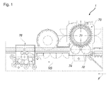
- Fig. 1 shows a treatment line for the manufacture and labeling of objects in the form of plastic containers, such as PET containers for drinks, hereinafter referred to briefly container.
- the container 2 (see. Fig. 10 ) have in the head area on no support ring on which the container 2 can be transported through the system 1.
- a conveyor line F is arranged a plurality of processing machines.
- the plant 1 comprises a rotating stretch blow molding machine 70 with an outlet star 74, which again adds the finished blown plastic container 2 to the conveyor line F.
- a furnace (not shown) is arranged in which the preforms (not shown) are brought to the required temperature so that they can be processed with the stretch blow molding machine 70.
- the transport device 71 is designed as a wheel. It is also conceivable that the transport device 71 may be formed as a substantially linear transport device.
- the preforms pass from the furnace via an inlet star 72 into the stretch blow molding machine 70.
- the stretch blow molding machine 70 is followed by a rotating labeling machine 76 along the processing path VS.
- the rotary labeling machine 76 comprises an inlet star 72 and an outlet star 74.
- the labeling machine 76 can furthermore be arranged downstream of the processing path VS, a rotating filling and closing machine (not shown).
- Each of the machines arranged along the processing line VS has its own motor, not shown, by means of which it can be continuously driven together with its variable speed starwheels.
- the Fig. 2 shows a machine head 56, on which the container 2 (see. Fig. 10 ) can be applied for labeling and further transported.
- the standing incoming containers (not shown) are of a conveyor belt (not shown) to an inlet star (not shown) passed, which transfers the container (not shown) to the machine head 56.
- centering units 10 (see FIG. Fig. 10 ) are attached, the containers via special centering bells 12 (see. Fig. 3 ) for further transport.
- the centering bells 12 are attached to stationary brackets 11 which are fixed to the machine head 56.
- a retainer 54 and Ausziehgabel attached which surrounds the centering bell 12 by about 180 degrees (see. Fig. 10 ).
- the retainer 54 is mounted below the machine support ring 58 such that the opening 55 of the retainer 54 in which the centering bell 12 is located opposite to this attachment to the machine support ring 58.
- the machine head 56 is driven by a rotary drive 50, preferably formed by a motor, so that it rotates about an axis of rotation R and the attached brackets 11 of the centering bell 12 and the retainer 54 are moved during the rotational movement.
- the machine head 56 can be used both in a labeling machine (not shown) and in a stretch blow molding machine (not shown).
- rotary transmission members 62 which may be individually driven by means of a toothed belt or the like (not shown) to bring the containers for labeling into the required position.
- the Fig. 3 shows a schematic side view of a centering unit 10 consisting of a centering bell 12 with receptacle 14.
- the centering bell 12 includes a plug-on head 22 which is connected to the holder 11 (see. Fig. 2 ), a withdrawal sleeve 24, a compression spring 28, a star wheel 30.
- the receptacle 14 for the mouth region 6 of the container 2 is arranged below the centering bell 12.
- the star wheel 30 are formed in connection with the receptacle 14 of the container 2.
- the receptacle 14 comprises sealing means 16, which provide a tight connection between the mouth region 6 of the container 2 or a preform 14 and the receptacle.
- the sealing means 16 may consist of O-rings 18 and / or clamping jaws 20.
- Fig. 4 shows a section AA perpendicular to the centering unit 10 of the Fig. 3 . From the sectional view can be seen how the individual elements of the centering bell 12 and receptacle 14 work together.
- the receptacle 14 can be moved, for example, over the star wheel 30 about the displacement path V up and down. This process is, for example, in an upward movement of the centering unit 10th triggered during operation of the machine. This upward movement is by means of a lifting cam (not shown), which on the machine head 56 (see. Fig. 2 ) is attached allows.
- the compression spring 28 is compressed by the star wheel 30, since the star plate 30 is connected via an inner guide 38 with the receptacle 14 and the withdrawal sleeve 24.
- the star wheel 30 engages with attached fingers 32 (see. Fig. 6 ) in guides 26 of the withdrawal sleeve 24 and moves upward along the displacement path V (see. Fig. 3, 4 . 5 and 6 ).
- Fig. 5 is a plan view of the centering unit 10 is shown.
- a receiving opening 34 is provided, into which the holder 11, which is attached to the machine head 56, can be inserted and fixed.
- Fig. 6 shows a section BB horizontally through the centering unit 10 from the Fig. 5 .
- the fingers 32 of the star wheel 30 are mounted offset therefrom, or in the exemplary embodiment form an odd number of fingers 32.
- the jaws 20, which are attached as a sealing means 16 to the receptacle 14 of the centering unit 10 have an odd number.
- Below the receptacle 14 is a connection 36 for a control and / or control valve 40 (see. Fig. 8 ) intended.
- the fingers 32 of the star wheel 30 can fulfill other functions. On the one hand, these serve as a stop or holding means of the compression spring 28 and on the other hand as a stop for the upper edge of the mouth region 6 of the container 2 (see. Fig. 10 ) or preforms (not shown).
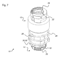
- the centering unit 10 is shown in a perspective view.
- the guides 26 for the fingers 32 of the star wheel 30 are clearly shown in the view.
- there is the contact surface of the compression spring 28 on the upper surfaces of the fingers 32 of the star wheel 30 and the arrangement of these fingers 32 and the O-rings 18 and the jaws 20 on the receptacle 14 of the centering unit 10 clearly visible.
- the receiving opening 34 for the holder 11 imaged on the plug-in head 22.
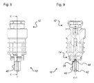
- FIGS. 8 and 9 correspond largely to the FIGS. 3 and 4 However, they differ from these by the control and / or control valve 40 attached to the connection 36.
- This regulating and / or control valve 40 is in the immediate vicinity of Outlet opening 44 of the centering unit 10 is positioned and ensures via a compressed air line 42 that in the container 2, which is attached to the receptacle 14 of the centering unit 10, the desired pressure can be produced (see. Fig. 10 ).
- the compressed air line 42 is arranged centrally in the centering unit 10 and with the holder 11 (see. Fig. 2 ) via a device which on the machine head 56 (see. Fig. 2 ) is connected.
- Fig. 10 shows a schematic representation of a connection of a container 2 and a centering unit 10. This compound can also be made instead of a container 2 with a preform (not shown). This may, for example, be advantageous for the stretch blow molding machine 72 (cf. Fig. 1 ), which was named at the beginning.
- the controlled separation of the container 2 from the centering bell 12 can, for example, be defined and controlled by means of a suitable lifting curve.
- Fig. 10 the bifurcated retaining device 54 can be seen, which supports the separation of the container 2 from the centering bell 12.
- the device according to the invention thus relates to containers or preforms without a support ring or with a support ring.
Landscapes
- Labeling Devices (AREA)
- Blow-Moulding Or Thermoforming Of Plastics Or The Like (AREA)
Applications Claiming Priority (1)
| Application Number | Priority Date | Filing Date | Title |
|---|---|---|---|
| DE102009003478A DE102009003478A1 (de) | 2009-02-13 | 2009-02-13 | Vorrichtung und Verfahren zum Etikettieren von Behältern |
Publications (3)
| Publication Number | Publication Date |
|---|---|
| EP2218648A2 true EP2218648A2 (fr) | 2010-08-18 |
| EP2218648A3 EP2218648A3 (fr) | 2013-03-27 |
| EP2218648B1 EP2218648B1 (fr) | 2014-04-30 |
Family
ID=42199837
Family Applications (1)
| Application Number | Title | Priority Date | Filing Date |
|---|---|---|---|
| EP20100151891 Not-in-force EP2218648B1 (fr) | 2009-02-13 | 2010-01-28 | Dispositif destinés à l'étiquetage de récipients |
Country Status (3)
| Country | Link |
|---|---|
| EP (1) | EP2218648B1 (fr) |
| CN (1) | CN101804878B (fr) |
| DE (1) | DE102009003478A1 (fr) |
Cited By (2)
| Publication number | Priority date | Publication date | Assignee | Title |
|---|---|---|---|---|
| DE102015224975A1 (de) | 2015-12-11 | 2017-06-14 | Krones Ag | Behandlungsmaschine für Behälter |
| DE102015224973A1 (de) | 2015-12-11 | 2017-06-14 | Krones Aktiengesellschaft | Behälterbehandlungsmaschine |
Families Citing this family (5)
| Publication number | Priority date | Publication date | Assignee | Title |
|---|---|---|---|---|
| DE102011087722A1 (de) * | 2011-12-05 | 2013-06-06 | Krones Ag | Vorrichtung und Verfahren zum Etikettieren von Behältern mit Etikettenhülsen |
| DE102014106573A1 (de) | 2014-05-09 | 2015-11-12 | Khs Gmbh | Halte- und Zentriereinrichtung, Behälterbehandlungsvorrichtung sowie Verfahren zur Behandlung von Behältern |
| DE202016105703U1 (de) | 2016-10-12 | 2018-01-15 | Krones Ag | Aufnahmeplattenvorrichtung und Rundläuferetikettiermaschine |
| DE102020112382A1 (de) * | 2020-05-07 | 2021-11-11 | Krones Aktiengesellschaft | Maschinenblock zum Herstellen und Abfüllen von Flaschen und Verfahren zum Steuern des Maschinenblocks |
| DE102023124698A1 (de) * | 2023-09-13 | 2025-03-13 | Khs Gmbh | Zentrierkörper und Behälterbehandlungsmaschine umfassend den Zentrierkörper |
Citations (3)
| Publication number | Priority date | Publication date | Assignee | Title |
|---|---|---|---|---|
| DE4125579A1 (de) | 1991-08-02 | 1993-02-04 | Alfill Getraenketechnik | Vorrichtung zum etikettieren von behaeltern |
| DE60110498T2 (de) | 2000-06-13 | 2006-02-23 | Sig Simonazzi S.P.A. | Selbsttätig rotierende Etikettiermaschine |
| DE60208736T2 (de) | 2001-04-20 | 2006-09-14 | Sig Simonazzi S.P.A. | Vorrichtung zum Greifen und Handhaben von Flaschen in einer Etikettiermaschine |
Family Cites Families (12)
| Publication number | Priority date | Publication date | Assignee | Title |
|---|---|---|---|---|
| US2600161A (en) * | 1950-07-13 | 1952-06-10 | Anchor Hocking Glass Corp | Means for holding and masking articles during coating |
| DE1029251B (de) * | 1954-10-07 | 1958-04-30 | Holstein & Kappert Maschf | Vorrichtung zum Behandeln von Flaschen |
| US3064714A (en) * | 1960-01-08 | 1962-11-20 | Dennison Mfg Co | Apparatus for applying indicia to articles |
| AT222043B (de) * | 1960-05-31 | 1962-06-25 | Dennison Mfg Co | Maschine zum Etikettieren von Flaschen od. dgl. |
| AT237536B (de) * | 1961-06-21 | 1964-12-28 | Dennison Mfg Co | Maschine zur Übertragung von Etiketten von einem Etiketten mitfuhrenden Trägerband auf zu etikettierende Gegenstände, z. B. Flaschen |
| US3261734A (en) * | 1962-08-13 | 1966-07-19 | Dennison Mfg Co | Method and apparatus for applying indicia to plastic bottles and the like |
| US3684418A (en) * | 1969-06-12 | 1972-08-15 | Erhard Langecker | Apparatus for applying labels or plates to blow molded thermoplastic hollow bodies |
| US3802942A (en) * | 1971-12-20 | 1974-04-09 | Owens Illinois Inc | Machine for producing a plastic-covered glass container |
| DE4131327A1 (de) * | 1991-09-20 | 1993-03-25 | Alfill Getraenketechnik | Vorrichtung zum halten von gefaessen |
| DE19806647A1 (de) * | 1998-02-18 | 1999-08-19 | Krones Ag | Verfahren und Vorrichtung zum Herstellen einer etikettierten Kunststoffflasche und ein Rohling für eine Kunststoffflasche |
| DE102005041120A1 (de) * | 2005-08-30 | 2007-03-01 | Krones Ag | Vorrichtung und Verfahren zum Höhenausgleich in Behälterbehandlungsmaschinen |
| DE102006062510A1 (de) * | 2006-12-29 | 2008-07-03 | Krones Ag | Maschine zum Etikettieren von Gefäßen |
-
2009
- 2009-02-13 DE DE102009003478A patent/DE102009003478A1/de not_active Withdrawn
-
2010
- 2010-01-28 EP EP20100151891 patent/EP2218648B1/fr not_active Not-in-force
- 2010-02-20 CN CN 201010114780 patent/CN101804878B/zh not_active Expired - Fee Related
Patent Citations (3)
| Publication number | Priority date | Publication date | Assignee | Title |
|---|---|---|---|---|
| DE4125579A1 (de) | 1991-08-02 | 1993-02-04 | Alfill Getraenketechnik | Vorrichtung zum etikettieren von behaeltern |
| DE60110498T2 (de) | 2000-06-13 | 2006-02-23 | Sig Simonazzi S.P.A. | Selbsttätig rotierende Etikettiermaschine |
| DE60208736T2 (de) | 2001-04-20 | 2006-09-14 | Sig Simonazzi S.P.A. | Vorrichtung zum Greifen und Handhaben von Flaschen in einer Etikettiermaschine |
Cited By (3)
| Publication number | Priority date | Publication date | Assignee | Title |
|---|---|---|---|---|
| DE102015224975A1 (de) | 2015-12-11 | 2017-06-14 | Krones Ag | Behandlungsmaschine für Behälter |
| DE102015224973A1 (de) | 2015-12-11 | 2017-06-14 | Krones Aktiengesellschaft | Behälterbehandlungsmaschine |
| WO2017097459A1 (fr) | 2015-12-11 | 2017-06-15 | Krones Ag | Machine de traitement de récipients |
Also Published As
| Publication number | Publication date |
|---|---|
| EP2218648B1 (fr) | 2014-04-30 |
| CN101804878A (zh) | 2010-08-18 |
| CN101804878B (zh) | 2012-11-28 |
| EP2218648A3 (fr) | 2013-03-27 |
| DE102009003478A1 (de) | 2010-08-19 |
Similar Documents
| Publication | Publication Date | Title |
|---|---|---|
| EP2218648B1 (fr) | Dispositif destinés à l'étiquetage de récipients | |
| EP2731780B1 (fr) | Acheminement et retrait en étoile unique de contenants pour des machines de traitement | |
| DE102009041160B4 (de) | Vorrichtung zum Herstellen von Flüssigkeitsbehältnissen | |
| EP2332867B1 (fr) | Dispositif et procédé de transport de récipients dotés d'un guidage inférieur | |
| EP2734463B1 (fr) | Module permettant d'aligner des récipients et procédé permettant d'aligner des récipients | |
| DE102009058222B4 (de) | Anlage zum Bedrucken von Behältern mit Einspannvorrichtungen mit eigenem Drehantrieb | |
| DE102014103671B3 (de) | Behälterbehandlungsmaschine sowie Verfahren zum Zu- und/oder Abführen von Behältern zu einer Behälterbehandlungsmaschine | |
| EP2556943A2 (fr) | Souffleuse, procédé d'échange de composants de stations de soufflage ainsi qu'installation de remplissage de boissons et/ou installation de fabrication de récipients de boissons | |
| EP2797834B1 (fr) | Dispositif et procédé pour remplir, fermer et étiqueter des récipients | |
| EP2948292A1 (fr) | Procédé pour faire fonctionner une installation de traitement de contenants, et installation de traitement de contenants | |
| EP2981491A1 (fr) | Machine de traitement de contenant et procédé d'amenée et/ou d'évacuation de contenants à une machine de traitement de contenant | |
| EP3090954B1 (fr) | Machine d'etiquetage destinee a appliquer une anse sur un recipient pet | |
| EP2429728B1 (fr) | Procédé et dispositif pour le nettoyage intérieur de boîtes présentant chacune une ouverture | |
| EP1584559B1 (fr) | Procédé et dispositif pour aligner des récipients pour substances liquides et coulantes, en particulier des boissons. | |
| DE102015224972A1 (de) | Behälterbehandlungsanlage mit einem Füller | |
| WO2015058889A1 (fr) | Dispositif et procédé de traitement d'emballages | |
| WO2017129316A1 (fr) | Élément de préhension pour porte-récipient, porte-récipient et voie de transport de récipients | |
| EP2539133A1 (fr) | Dispositif et procédé pour fabriquer des récipients en matière plastique étiquetés | |
| DE102006042711B4 (de) | Verfahren und Vorrichtung zur Herstellung von Kunststoffverpackungsbehältern | |
| EP3386870B1 (fr) | Machine de traitement des recipients | |
| DE102012101239A1 (de) | Blasmaschine, transporteinrichtung und verfahren zum blasformen eines behälters mit der blasmaschine | |
| WO2017144157A2 (fr) | Dispositif d'usinage, installation et procédé d'usinage pour des contenants de différents types | |
| DE102009007138A1 (de) | Vorrichtung und Verfahren zum Behandeln von Behältnissen | |
| WO2019210989A1 (fr) | Procédé et dispositif de fabrication d'unités d'emballage comprenant chacune au moins un article et un reconditionnement recevant l'article | |
| DE102009003649A1 (de) | Vorrichtung und Verfahren zur Behälterbehandlung |
Legal Events
| Date | Code | Title | Description |
|---|---|---|---|
| PUAI | Public reference made under article 153(3) epc to a published international application that has entered the european phase |
Free format text: ORIGINAL CODE: 0009012 |
|
| AK | Designated contracting states |
Kind code of ref document: A2 Designated state(s): AT BE BG CH CY CZ DE DK EE ES FI FR GB GR HR HU IE IS IT LI LT LU LV MC MK MT NL NO PL PT RO SE SI SK SM TR |
|
| AX | Request for extension of the european patent |
Extension state: AL BA RS |
|
| PUAL | Search report despatched |
Free format text: ORIGINAL CODE: 0009013 |
|
| AK | Designated contracting states |
Kind code of ref document: A3 Designated state(s): AT BE BG CH CY CZ DE DK EE ES FI FR GB GR HR HU IE IS IT LI LT LU LV MC MK MT NL NO PL PT RO SE SI SK SM TR |
|
| AX | Request for extension of the european patent |
Extension state: AL BA RS |
|
| RIC1 | Information provided on ipc code assigned before grant |
Ipc: B65C 9/02 20060101AFI20130219BHEP Ipc: B65C 3/26 20060101ALI20130219BHEP |
|
| 17P | Request for examination filed |
Effective date: 20130408 |
|
| GRAP | Despatch of communication of intention to grant a patent |
Free format text: ORIGINAL CODE: EPIDOSNIGR1 |
|
| INTG | Intention to grant announced |
Effective date: 20131210 |
|
| GRAS | Grant fee paid |
Free format text: ORIGINAL CODE: EPIDOSNIGR3 |
|
| GRAA | (expected) grant |
Free format text: ORIGINAL CODE: 0009210 |
|
| AK | Designated contracting states |
Kind code of ref document: B1 Designated state(s): AT BE BG CH CY CZ DE DK EE ES FI FR GB GR HR HU IE IS IT LI LT LU LV MC MK MT NL NO PL PT RO SE SI SK SM TR |
|
| REG | Reference to a national code |
Ref country code: GB Ref legal event code: FG4D Free format text: NOT ENGLISH Ref country code: CH Ref legal event code: EP |
|
| REG | Reference to a national code |
Ref country code: AT Ref legal event code: REF Ref document number: 664945 Country of ref document: AT Kind code of ref document: T Effective date: 20140515 |
|
| REG | Reference to a national code |
Ref country code: IE Ref legal event code: FG4D Free format text: LANGUAGE OF EP DOCUMENT: GERMAN |
|
| REG | Reference to a national code |
Ref country code: DE Ref legal event code: R096 Ref document number: 502010006778 Country of ref document: DE Effective date: 20140618 |
|
| REG | Reference to a national code |
Ref country code: LT Ref legal event code: MG4D |
|
| REG | Reference to a national code |
Ref country code: NL Ref legal event code: VDEP Effective date: 20140430 |
|
| PG25 | Lapsed in a contracting state [announced via postgrant information from national office to epo] |
Ref country code: GR Free format text: LAPSE BECAUSE OF FAILURE TO SUBMIT A TRANSLATION OF THE DESCRIPTION OR TO PAY THE FEE WITHIN THE PRESCRIBED TIME-LIMIT Effective date: 20140731 Ref country code: FI Free format text: LAPSE BECAUSE OF FAILURE TO SUBMIT A TRANSLATION OF THE DESCRIPTION OR TO PAY THE FEE WITHIN THE PRESCRIBED TIME-LIMIT Effective date: 20140430 Ref country code: LT Free format text: LAPSE BECAUSE OF FAILURE TO SUBMIT A TRANSLATION OF THE DESCRIPTION OR TO PAY THE FEE WITHIN THE PRESCRIBED TIME-LIMIT Effective date: 20140430 Ref country code: IS Free format text: LAPSE BECAUSE OF FAILURE TO SUBMIT A TRANSLATION OF THE DESCRIPTION OR TO PAY THE FEE WITHIN THE PRESCRIBED TIME-LIMIT Effective date: 20140830 Ref country code: BG Free format text: LAPSE BECAUSE OF FAILURE TO SUBMIT A TRANSLATION OF THE DESCRIPTION OR TO PAY THE FEE WITHIN THE PRESCRIBED TIME-LIMIT Effective date: 20140730 Ref country code: NO Free format text: LAPSE BECAUSE OF FAILURE TO SUBMIT A TRANSLATION OF THE DESCRIPTION OR TO PAY THE FEE WITHIN THE PRESCRIBED TIME-LIMIT Effective date: 20140730 Ref country code: CY Free format text: LAPSE BECAUSE OF FAILURE TO SUBMIT A TRANSLATION OF THE DESCRIPTION OR TO PAY THE FEE WITHIN THE PRESCRIBED TIME-LIMIT Effective date: 20140430 Ref country code: NL Free format text: LAPSE BECAUSE OF FAILURE TO SUBMIT A TRANSLATION OF THE DESCRIPTION OR TO PAY THE FEE WITHIN THE PRESCRIBED TIME-LIMIT Effective date: 20140430 |
|
| PG25 | Lapsed in a contracting state [announced via postgrant information from national office to epo] |
Ref country code: PL Free format text: LAPSE BECAUSE OF FAILURE TO SUBMIT A TRANSLATION OF THE DESCRIPTION OR TO PAY THE FEE WITHIN THE PRESCRIBED TIME-LIMIT Effective date: 20140430 Ref country code: HR Free format text: LAPSE BECAUSE OF FAILURE TO SUBMIT A TRANSLATION OF THE DESCRIPTION OR TO PAY THE FEE WITHIN THE PRESCRIBED TIME-LIMIT Effective date: 20140430 Ref country code: SE Free format text: LAPSE BECAUSE OF FAILURE TO SUBMIT A TRANSLATION OF THE DESCRIPTION OR TO PAY THE FEE WITHIN THE PRESCRIBED TIME-LIMIT Effective date: 20140430 Ref country code: LV Free format text: LAPSE BECAUSE OF FAILURE TO SUBMIT A TRANSLATION OF THE DESCRIPTION OR TO PAY THE FEE WITHIN THE PRESCRIBED TIME-LIMIT Effective date: 20140430 Ref country code: ES Free format text: LAPSE BECAUSE OF FAILURE TO SUBMIT A TRANSLATION OF THE DESCRIPTION OR TO PAY THE FEE WITHIN THE PRESCRIBED TIME-LIMIT Effective date: 20140430 |
|
| PG25 | Lapsed in a contracting state [announced via postgrant information from national office to epo] |
Ref country code: PT Free format text: LAPSE BECAUSE OF FAILURE TO SUBMIT A TRANSLATION OF THE DESCRIPTION OR TO PAY THE FEE WITHIN THE PRESCRIBED TIME-LIMIT Effective date: 20140901 |
|
| PG25 | Lapsed in a contracting state [announced via postgrant information from national office to epo] |
Ref country code: CZ Free format text: LAPSE BECAUSE OF FAILURE TO SUBMIT A TRANSLATION OF THE DESCRIPTION OR TO PAY THE FEE WITHIN THE PRESCRIBED TIME-LIMIT Effective date: 20140430 Ref country code: SK Free format text: LAPSE BECAUSE OF FAILURE TO SUBMIT A TRANSLATION OF THE DESCRIPTION OR TO PAY THE FEE WITHIN THE PRESCRIBED TIME-LIMIT Effective date: 20140430 Ref country code: DK Free format text: LAPSE BECAUSE OF FAILURE TO SUBMIT A TRANSLATION OF THE DESCRIPTION OR TO PAY THE FEE WITHIN THE PRESCRIBED TIME-LIMIT Effective date: 20140430 Ref country code: RO Free format text: LAPSE BECAUSE OF FAILURE TO SUBMIT A TRANSLATION OF THE DESCRIPTION OR TO PAY THE FEE WITHIN THE PRESCRIBED TIME-LIMIT Effective date: 20140430 Ref country code: EE Free format text: LAPSE BECAUSE OF FAILURE TO SUBMIT A TRANSLATION OF THE DESCRIPTION OR TO PAY THE FEE WITHIN THE PRESCRIBED TIME-LIMIT Effective date: 20140430 |
|
| REG | Reference to a national code |
Ref country code: DE Ref legal event code: R097 Ref document number: 502010006778 Country of ref document: DE |
|
| PLBE | No opposition filed within time limit |
Free format text: ORIGINAL CODE: 0009261 |
|
| STAA | Information on the status of an ep patent application or granted ep patent |
Free format text: STATUS: NO OPPOSITION FILED WITHIN TIME LIMIT |
|
| 26N | No opposition filed |
Effective date: 20150202 |
|
| REG | Reference to a national code |
Ref country code: DE Ref legal event code: R097 Ref document number: 502010006778 Country of ref document: DE Effective date: 20150202 |
|
| PG25 | Lapsed in a contracting state [announced via postgrant information from national office to epo] |
Ref country code: BE Free format text: LAPSE BECAUSE OF NON-PAYMENT OF DUE FEES Effective date: 20150131 |
|
| PG25 | Lapsed in a contracting state [announced via postgrant information from national office to epo] |
Ref country code: SI Free format text: LAPSE BECAUSE OF FAILURE TO SUBMIT A TRANSLATION OF THE DESCRIPTION OR TO PAY THE FEE WITHIN THE PRESCRIBED TIME-LIMIT Effective date: 20140430 |
|
| REG | Reference to a national code |
Ref country code: CH Ref legal event code: PL |
|
| PG25 | Lapsed in a contracting state [announced via postgrant information from national office to epo] |
Ref country code: LU Free format text: LAPSE BECAUSE OF FAILURE TO SUBMIT A TRANSLATION OF THE DESCRIPTION OR TO PAY THE FEE WITHIN THE PRESCRIBED TIME-LIMIT Effective date: 20150128 |
|
| GBPC | Gb: european patent ceased through non-payment of renewal fee |
Effective date: 20150128 |
|
| PG25 | Lapsed in a contracting state [announced via postgrant information from national office to epo] |
Ref country code: MC Free format text: LAPSE BECAUSE OF FAILURE TO SUBMIT A TRANSLATION OF THE DESCRIPTION OR TO PAY THE FEE WITHIN THE PRESCRIBED TIME-LIMIT Effective date: 20140430 |
|
| PG25 | Lapsed in a contracting state [announced via postgrant information from national office to epo] |
Ref country code: CH Free format text: LAPSE BECAUSE OF NON-PAYMENT OF DUE FEES Effective date: 20150131 Ref country code: GB Free format text: LAPSE BECAUSE OF NON-PAYMENT OF DUE FEES Effective date: 20150128 Ref country code: LI Free format text: LAPSE BECAUSE OF NON-PAYMENT OF DUE FEES Effective date: 20150131 |
|
| REG | Reference to a national code |
Ref country code: IE Ref legal event code: MM4A |
|
| REG | Reference to a national code |
Ref country code: FR Ref legal event code: PLFP Year of fee payment: 7 |
|
| PG25 | Lapsed in a contracting state [announced via postgrant information from national office to epo] |
Ref country code: IE Free format text: LAPSE BECAUSE OF NON-PAYMENT OF DUE FEES Effective date: 20150128 |
|
| REG | Reference to a national code |
Ref country code: AT Ref legal event code: MM01 Ref document number: 664945 Country of ref document: AT Kind code of ref document: T Effective date: 20150128 |
|
| PG25 | Lapsed in a contracting state [announced via postgrant information from national office to epo] |
Ref country code: AT Free format text: LAPSE BECAUSE OF NON-PAYMENT OF DUE FEES Effective date: 20150128 |
|
| REG | Reference to a national code |
Ref country code: FR Ref legal event code: PLFP Year of fee payment: 8 |
|
| PG25 | Lapsed in a contracting state [announced via postgrant information from national office to epo] |
Ref country code: MT Free format text: LAPSE BECAUSE OF FAILURE TO SUBMIT A TRANSLATION OF THE DESCRIPTION OR TO PAY THE FEE WITHIN THE PRESCRIBED TIME-LIMIT Effective date: 20140430 |
|
| PG25 | Lapsed in a contracting state [announced via postgrant information from national office to epo] |
Ref country code: SM Free format text: LAPSE BECAUSE OF FAILURE TO SUBMIT A TRANSLATION OF THE DESCRIPTION OR TO PAY THE FEE WITHIN THE PRESCRIBED TIME-LIMIT Effective date: 20140430 Ref country code: HU Free format text: LAPSE BECAUSE OF FAILURE TO SUBMIT A TRANSLATION OF THE DESCRIPTION OR TO PAY THE FEE WITHIN THE PRESCRIBED TIME-LIMIT; INVALID AB INITIO Effective date: 20100128 |
|
| PG25 | Lapsed in a contracting state [announced via postgrant information from national office to epo] |
Ref country code: TR Free format text: LAPSE BECAUSE OF FAILURE TO SUBMIT A TRANSLATION OF THE DESCRIPTION OR TO PAY THE FEE WITHIN THE PRESCRIBED TIME-LIMIT Effective date: 20140430 |
|
| REG | Reference to a national code |
Ref country code: FR Ref legal event code: PLFP Year of fee payment: 9 |
|
| PG25 | Lapsed in a contracting state [announced via postgrant information from national office to epo] |
Ref country code: MK Free format text: LAPSE BECAUSE OF FAILURE TO SUBMIT A TRANSLATION OF THE DESCRIPTION OR TO PAY THE FEE WITHIN THE PRESCRIBED TIME-LIMIT Effective date: 20140430 |
|
| PGFP | Annual fee paid to national office [announced via postgrant information from national office to epo] |
Ref country code: FR Payment date: 20231212 Year of fee payment: 15 |
|
| PGFP | Annual fee paid to national office [announced via postgrant information from national office to epo] |
Ref country code: DE Payment date: 20231205 Year of fee payment: 15 |
|
| PGFP | Annual fee paid to national office [announced via postgrant information from national office to epo] |
Ref country code: IT Payment date: 20231212 Year of fee payment: 15 |
|
| REG | Reference to a national code |
Ref country code: DE Ref legal event code: R082 Ref document number: 502010006778 Country of ref document: DE Representative=s name: BENNINGER, JOHANNES, DIPL.-ING., DE |
|
| REG | Reference to a national code |
Ref country code: DE Ref legal event code: R119 Ref document number: 502010006778 Country of ref document: DE |
|
| PG25 | Lapsed in a contracting state [announced via postgrant information from national office to epo] |
Ref country code: DE Free format text: LAPSE BECAUSE OF NON-PAYMENT OF DUE FEES Effective date: 20250801 |
|
| PG25 | Lapsed in a contracting state [announced via postgrant information from national office to epo] |
Ref country code: FR Free format text: LAPSE BECAUSE OF NON-PAYMENT OF DUE FEES Effective date: 20250131 |
|
| PG25 | Lapsed in a contracting state [announced via postgrant information from national office to epo] |
Ref country code: IT Free format text: LAPSE BECAUSE OF NON-PAYMENT OF DUE FEES Effective date: 20250128 |