EP2218655A1 - Aerosol container - Google Patents
Aerosol container Download PDFInfo
- Publication number
- EP2218655A1 EP2218655A1 EP10165241A EP10165241A EP2218655A1 EP 2218655 A1 EP2218655 A1 EP 2218655A1 EP 10165241 A EP10165241 A EP 10165241A EP 10165241 A EP10165241 A EP 10165241A EP 2218655 A1 EP2218655 A1 EP 2218655A1
- Authority
- EP
- European Patent Office
- Prior art keywords
- foodproduct
- upstream
- receiving space
- dispensing head
- container
- Prior art date
- Legal status (The legal status is an assumption and is not a legal conclusion. Google has not performed a legal analysis and makes no representation as to the accuracy of the status listed.)
- Granted
Links
Images


Classifications
-
- B—PERFORMING OPERATIONS; TRANSPORTING
- B65—CONVEYING; PACKING; STORING; HANDLING THIN OR FILAMENTARY MATERIAL
- B65D—CONTAINERS FOR STORAGE OR TRANSPORT OF ARTICLES OR MATERIALS, e.g. BAGS, BARRELS, BOTTLES, BOXES, CANS, CARTONS, CRATES, DRUMS, JARS, TANKS, HOPPERS, FORWARDING CONTAINERS; ACCESSORIES, CLOSURES, OR FITTINGS THEREFOR; PACKAGING ELEMENTS; PACKAGES
- B65D83/00—Containers or packages with special means for dispensing contents
- B65D83/14—Containers for dispensing liquid or semi-liquid contents by internal gaseous pressure, i.e. aerosol containers comprising propellant
- B65D83/28—Nozzles, nozzle fittings or accessories specially adapted therefor
- B65D83/30—Nozzles, nozzle fittings or accessories specially adapted therefor for guiding the flow of the dispensed content, e.g. funnels or hoods
-
- B—PERFORMING OPERATIONS; TRANSPORTING
- B65—CONVEYING; PACKING; STORING; HANDLING THIN OR FILAMENTARY MATERIAL
- B65D—CONTAINERS FOR STORAGE OR TRANSPORT OF ARTICLES OR MATERIALS, e.g. BAGS, BARRELS, BOTTLES, BOXES, CANS, CARTONS, CRATES, DRUMS, JARS, TANKS, HOPPERS, FORWARDING CONTAINERS; ACCESSORIES, CLOSURES, OR FITTINGS THEREFOR; PACKAGING ELEMENTS; PACKAGES
- B65D83/00—Containers or packages with special means for dispensing contents
- B65D83/14—Containers for dispensing liquid or semi-liquid contents by internal gaseous pressure, i.e. aerosol containers comprising propellant
- B65D83/145—Containers for dispensing liquid or semi-liquid contents by internal gaseous pressure, i.e. aerosol containers comprising propellant with tamper-indicating means, e.g. located in front of nozzle outlets
-
- B—PERFORMING OPERATIONS; TRANSPORTING
- B65—CONVEYING; PACKING; STORING; HANDLING THIN OR FILAMENTARY MATERIAL
- B65D—CONTAINERS FOR STORAGE OR TRANSPORT OF ARTICLES OR MATERIALS, e.g. BAGS, BARRELS, BOTTLES, BOXES, CANS, CARTONS, CRATES, DRUMS, JARS, TANKS, HOPPERS, FORWARDING CONTAINERS; ACCESSORIES, CLOSURES, OR FITTINGS THEREFOR; PACKAGING ELEMENTS; PACKAGES
- B65D83/00—Containers or packages with special means for dispensing contents
- B65D83/14—Containers for dispensing liquid or semi-liquid contents by internal gaseous pressure, i.e. aerosol containers comprising propellant
- B65D83/16—Actuating means
- B65D83/20—Actuator caps
-
- B—PERFORMING OPERATIONS; TRANSPORTING
- B65—CONVEYING; PACKING; STORING; HANDLING THIN OR FILAMENTARY MATERIAL
- B65D—CONTAINERS FOR STORAGE OR TRANSPORT OF ARTICLES OR MATERIALS, e.g. BAGS, BARRELS, BOTTLES, BOXES, CANS, CARTONS, CRATES, DRUMS, JARS, TANKS, HOPPERS, FORWARDING CONTAINERS; ACCESSORIES, CLOSURES, OR FITTINGS THEREFOR; PACKAGING ELEMENTS; PACKAGES
- B65D83/00—Containers or packages with special means for dispensing contents
- B65D83/14—Containers for dispensing liquid or semi-liquid contents by internal gaseous pressure, i.e. aerosol containers comprising propellant
- B65D83/40—Closure caps
-
- Y—GENERAL TAGGING OF NEW TECHNOLOGICAL DEVELOPMENTS; GENERAL TAGGING OF CROSS-SECTIONAL TECHNOLOGIES SPANNING OVER SEVERAL SECTIONS OF THE IPC; TECHNICAL SUBJECTS COVERED BY FORMER USPC CROSS-REFERENCE ART COLLECTIONS [XRACs] AND DIGESTS
- Y10—TECHNICAL SUBJECTS COVERED BY FORMER USPC
- Y10T—TECHNICAL SUBJECTS COVERED BY FORMER US CLASSIFICATION
- Y10T29/00—Metal working
- Y10T29/49—Method of mechanical manufacture
- Y10T29/49826—Assembling or joining
Definitions
- the invention relates to an aerosol container, comprising:
- a container, in which the foodproduct comprises cream, is currently marketed and sold by the applicant.
- the known container is lightweight, compact and designed to be disposed after being used-up.
- cream is ejected via the dispensing head and undergoes a so called 'overrun', such that a 'spray cream' which resembles common whipped cream, is obtained.
- the foodproduct receiving space is a substantially cylindrical space.
- the container comprises valve means and a small discharge nozzle.
- the nozzle sprays the cream into the cylindrical space, upon which the cream preferably expands to a desired degree and is agitated vigorously due to expanding propellant.
- a downstream discharge opening of the foodproduct receiving space is partly blocked by said cream shaping projections.
- the known foodproduct shaping projections are curved towards each other to press outflowing cream locally inwardly, to profile the cream.
- the contour of resulting cream, discharged from the container is provided with a desired relief, particularly indents which have been pressed or cut into the cream by the mentioned projections of the dispensing head.
- a thus shaped cream is desired in applications where a small amount of cream (i.e. a dot or rosette of cream) is to decorate a food product, such as pie, or a beverage such as chocolate milk or coffee.
- An object of the present invention is to provide an aerosol container which can achieve an improved shaping of the foodproduct, such that a dispensed spray foodproduct having an improved sharp relief can be obtained there-from.
- the aerosol container is characterised in that the foodproduct receiving space comprises an upstream foodproduct receiving space that widens, viewed in a foodproduct discharge direction, wherein the ratio between a length L1 of the foodproduct receiving space and a maximum diameter D1 of that space is in the range of 1:2-2:1.
- a maximum diameter of the foodproduct receiving space of the dispensing head is preferably larger than about 2 cm.
- the aerosol container can generate spray foodproduct having a relatively sharp relief.
- the present container can deliver a small amount of foodproduct having a rosette-shape with a sharp relief, the relief comprising sharp outer edges and intermediate 'valleys' that have been pressed into the foodproduct by respective foodproduct shaping projections of the discharge head.
- the foodproduct comprises cream.
- cream can be a main ingredient of the foodproduct.
- Other foodproducts, to be applied in the present invention can be, for example: deserts, mousses, food garnishing products or different foodproducts.
- the aerosol container according to the present invention provides significantly improved shaping of dispensed foodproduct, during the spraying of the foodproduct.
- an explanation might be that the widening foodproduct receiving space can provide a better controlled outflow of the foodproduct, which can still be expanding in the foodproduct receiving area, which might benefit the desired operation of the downstream foodproduct shaping projections.
- the present foodproduct dispensing and shaping head can be made relatively compact and short, compared to conventional aerosol foodproduct dispensing heads, and can be cleansed thoroughly with relative ease.
- automatic whipping cream dispensing machines having discharge heads with projections to shape the cream
- These machines can provide a dot of whipped cream having a well defined, sharp rosette relief as well.
- the known automatic whipping cream dispensers operate in an entirely different manner than the above-described aerosol container, as will be appreciated by the skilled person.
- good results can be obtained in case at least a first part of an inner surface of the upstream dispensing head part, which defines at least a first part of the upstream foodproduct receiving space, extends along a virtual first conical plane.
- the apex angle of the first conical virtual plane is in the range of 45-180 degrees, particularly in the range of 80-120 degrees.
- a second part of the inner surface of the upstream dispensing head part, defining at least a second part of the upstream foodproduct receiving space extends upstream with respect to the first part of that surface, and extends along a virtual second conical plane.
- the apex angle of the second conical virtual plane can be smaller than the apex angle of the first conical plane, and is for example in the range of about 5-45 degrees, and particularly in the range of 10-30 degrees.
- an optional second part of the inner surface of the upstream dispensing head part can also be shaped differently, for example cylindrically.
- the inner surface of the distal part of the dispensing head can substantially extend along a virtual third conical surface, an apex angle of the third conical surface preferably being in the range of about 45-135 degrees and more preferably in the range of about 60-100 degrees, for example about 70 degrees.
- the dispensing head can be dimensioned in various ways, however, it has been found that good foodproduct shaping results are provided when a length of the foodproduct receiving space, measured from a bottom of that space to a downstream lateral foodproduct discharge opening of the dispensing head, is relatively short, for example smaller than 3 cm, or in the range of about 2-3 cm.
- the foodproduct shaping projections can be located at a relatively short distance from the foodproduct discharge means of the container.
- a maximum diameter of the foodproduct receiving space of the dispensing head can be relatively large, for example larger than 2 cm, or in the range of 2-3 cm.
- such broad foodproduct receiving space can lead to a relatively low foodproduct discharge speed (at least: lower than obtained with conventional aerosol foodproduct dispensing heads) at downstream foodproduct shaping projections, which might also lead to improved operation of the foodproduct shaping projections.
- the distal part of the dispensing head can be provided with foodproduct dispensing apertures or slits, such that opposite longitudinal sides of the foodproduct shaping projections abut these apertures.
- these foodproduct dispensing apertures extend from an upstream end of an upstream contour of the widening foodproduct receiving space part.
- an aerosol container for example a container according to the invention, wherein the method comprises:
- the assembly of the container can be simplified, so that throughput can be improved, for example compared to a manufacturing method wherein head and cap are being joined independently, in sequence, with the container.
- the cap is a tamper evident cap, to indicate tampering.
- the head can comprise a tamper evident configuration.
- embodiments of the invention are also characterised by the features of claim 15.
- Figures 1-8 shown an embodiment of an aerosol container 1, to discharge and shape/model a foodproduct.
- the container is compact (for example with an overall volume less than 11), of a lightweight construction.
- a packed container, comprising the foodproduct can weigh less than 1 kg, such as about 750 or 250 g.
- the container as such is made of tinplate or aluminium, coated on the inside, and has a substantially cylindrical shape.
- the present aerosol container 1 is of a non-refillable type, to be discarded after being used up.
- the present container 1 is of a relatively inexpensive, durable construction, having few components.
- the container 1 comprises a reservoir 2 containing the foodproduct, the foodproduct being safe for consumption, and a suitable propellant.
- the aerosol container can be packed with foodproduct and propellant, the initial pressure in the container being for example in the range of 7-18 atmospheres, depending on the amount of packed foodproduct, as will be appreciated by the skilled person.
- the propellant can consist of one or more gasses acceptable from the viewpoint of food technology, for example a gas which substantially dissolves in the foodproduct, a gas which substantially does not dissolve in the foodproduct and a combination of these gasses.
- the propellant can comprise CO2, nitrogen (N2), laughing gas (N2O) or a combination of these gasses (such as nitrogen and laughing gas).
- N2 nitrogen
- N2O laughing gas
- 15-25 w% (weight%) of the propellant can be N2 and the remainder of the propellant (i.e. 85-75 w%) can be N2O.
- the propellant can be packed separately from the foodproduct, for example in the case that the container is provided with a movable or flexible partition to provide such separation (such as in European patent application EP 1 061 006 A1 ).
- the propellant and foodproduct are packed together, in the same reservoir, in the aerosol container.
- the foodproduct comprises cream.
- the "spray cream” that is obtained from use of the present aerosol container 1 generally differs from conventional whipping cream (obtained from manually or automatically whipping common cream without using a cream propellant) to a high degree.
- the foodproduct can comprise various other ingredients, for example sugar, emulsifier, stabiliser, aroma.
- the cream has a fat content in the range of about 5%-50%, for example about 40%.
- An other cream composition can include a fat milk constituent (particularly cream, or common cream) and a non-fat milk constituent (for example skimmed milk), see EP 1 061 006 A1 .
- a cream foodproduct can comprise at least 80 w% of one or more milk constituents, and preferably at least circa 90 w%.
- the present container 1 is also provided with operable discharge means N (partly shown in Fig. 8 ) to discharge the foodproduct from the reservoir 2 into the dispensing head 10.
- the discharge means are firmly, undetachably, attached to the container 1.
- the present container 1 comprises a generally mushroom shaped dispensing head 10 defining a foodproduct receiving space 11 to receive the foodproduct from the discharge means, a distal part 15 of the head 10 (which part is located downstream, viewed in a general foodproduct flow direction, in longitudinal/axial container direction) having foodproduct shaping projections 12.
- the present container 1 is configured to be used upside down, with the dispensing head 10 substantially in a downward direction, and therefore does not comprise a dip-tube dispensing mechanism.
- the foodproduct discharge means of the container can be provided with operable valve means (not depicted), comprising a downwardly (i.e. towards a container bottom) depressible foodproduct ejection nozzle N (see Fig. 8 ) and spring means to counteract the depressing of the nozzle, such as in a currently marketed spray foodproduct aerosol container, as will be appreciated by the skilled person.
- operable valve means comprising a downwardly (i.e. towards a container bottom) depressible foodproduct ejection nozzle N (see Fig. 8 ) and spring means to counteract the depressing of the nozzle, such as in a currently marketed spray foodproduct aerosol container, as will be appreciated by the skilled person.
- depressing of the foodproduct ejection nozzle N leads to opening of the valve means so that foodproduct and part of the propellant can be ejected into the foodproduct receiving space 11 of the dispensing head 10, to be shaped and dispensed by the dispensing head 10.
- Mentioned spring means
- the foodproduct dispensing head 10 is provided with an integral ring shaped connecting member 3 which is coupled to a circumferential flange of a top part of the container.
- an upstream part of the dispensing head 10 comprises a nozzle receiving aperture 21 to cooperate with the nozzle of the container 1 .
- a bottom of the foodproduct receiving area 11 of the head 11 comprises a relatively broad first foodproduct passage extending opposite the foodproduct ejection nozzle after assembly, to receive foodproduct there-from.
- the first foodproduct passage is covered in an axial direction (i.e., axial with respect to a centre line L of the container 1) by a foodproduct dispersing member 23, wherein a plurality of second passages 24 (three in the present embodiment) extend through the dispersing member 23 in lateral directions.
- widths W of the second passages 24 can be smaller than 1 mm.
- the dispensing head 10 can also be configured in a different manner to receive foodproduct from the dispensing nozzle N, as will be appreciated by the skilled person.
- the dispensing head 10 is movably connected to the connecting member 3, particularly tiltable about a tilting axis T (see Fig. 6 ), to depress the foodproduct ejection nozzle N of the container 1.
- the head 10 comprises a knob part 22 for manual activation of dispensing of the foodproduct.
- activation of the discharge means of the container 1 can be achieved by manually operating (i.e. depressing, tilting) of the dispensing head 10.
- the foodproduct dispensing head is not movable with respect to the container 1, and a dedicated operating mechanism can be provided to activate the foodproduct dispensing means.
- the foodproduct is first packed into the reservoir 2 via a filling aperture in the top of the container, after which the filling aperture is sealed, by assembly of the discharge means onto the container.
- the propellant can be packed into the reservoir 2, preferably via the discharge means.
- the discharge means also serve as a filling means, to supply propellant to the reservoir 2 during the manufacture of the container.
- the container can be provided with a cap 20, preferably of a tamper evident configuration, to cover dispensing head, wherein the discharge means and dispensing head as such are preferably not provided with a tamper-evident configuration but are directly operable after removal of the cap from the container.
- a tamper-evident mechanism of the cap can be configured in various ways, and can comprise a breaking member 29 to break or rupture a tamper-evident connection between the cap 20 and a remaining part of the container, tearing means, deformation means, a one-way release or unlocking mechanism, or other suitable means.
- the discharge means and dispensing head can be operated in a logical and safe manner by a user, without the user needing to read a manual to understand the operation. Still, since the cap is tamper-evident, a first use of the container can be indicated and tampering of the container can be avoided.
- the aerosol container 1 comprising:
- the cap 20 and the head 10 are joined with the aerosol container 1, at the same time, such that the head 10 can cooperate with the discharge means of the container 1 after the joining of these components.
- the cap is the a tamper-evident cap 20, having a mentioned tamper evident configuration to indicate a first removal of the cap from the container 1.
- the tamper evident configuration can be configured, for example, to become operable by the joining of the cap/head-assembly with the container 1 (so that a subsequent removal of the cap from the container can be indicated by the tamper evident means).
- the joining of the cap and head with the container preferably does not lead to premature activation (for example rupture) of tamper evident means.
- the dispensing head advantageously has an upstream foodproduct receiving part 16 having an inner surface with a diameter which widens when viewed along a foodproduct discharge direction (i.e., when viewed along the mentioned axial direction).
- the inner surface of the upstream head part 16 (which surface is faced towards the centre line of the head) defines a first, widening, frusco-conical foodproduct receiving space part 11A (i.e., widening when viewed in a dispensing direction, axially away from the bottom of the foodproduct receiving space).
- the first part 17a of the inner surface of the upstream dispensing head part 16 extends along a virtual first conical plane (schematically indicated by dashed lines C1 in Fig. 6 ).
- the apex angle ⁇ 1 of the first conical virtual plane is in the range of 45-180 degrees, particularly in the range of 45-135 degrees degrees and more particularly 80-120.
- a second part 17b of the inner surface of the upstream dispensing head part 16, defining at least a second (frusco-conical) part 11B of the upstream foodproduct receiving space extends upstream with respect to the first part 17a of that surface, and extends along a virtual second conical plane.
- the apex angle ⁇ 2 of the second conical virtual plane C2 is smaller than the apex angle ⁇ 1 of the first conical plane C1, and is for example in the range of about 5-45 degrees, and particularly in the range of 10-30 degrees.
- the bottom of the foodproduct receiving space 11 abuts the second part 11B of that space 11, and the mentioned second foodproduct dispersing passages 24 lead into the radially most narrow part of the foodproduct receiving space.
- the inner surface 15a of the distal part 15 of the dispensing head 10 substantially extends along a virtual third conical surface C3.
- the apex angle ⁇ 3 of the third conical surface is preferably in the range of about 45-135 degrees and more preferably in the range of about 60-100 degrees, for example in the range of 70-80 degrees.
- improved operation can be provided in the case that the apex angle ⁇ 1 of a mentioned first conical surface is at least 10 degrees larger than the apex angle ⁇ 3 of the third conical surface.
- apex angle ⁇ 1 can be about 120°
- apex angle ⁇ 2 can be about 16°
- apex angle ⁇ 3 can be about 72°.
- the foodproduct shaping projections 12 abut foodproduct dispensing passages or apertures 19, the passages 19 extending from an upstream end of an upstream contour of the widening foodproduct receiving space part.
- the upstream ends of these foodproduct dispensing passages 19 are located at the widest part of the dispensing head (i.e., the radially widest part of the foodproduct receiving space 11), at the edge between the distal head part 15 and the upstream widening head part 16.
- Downstream ends of the foodproduct dispensing passages 19 join a central downstream main foodproduct discharge opening 18 of the dispensing head 10.
- the lateral diameter D2 of the main discharge opening 18 can be larger than the diameter D3 of the opposite bottom surface area of the foodproduct receiving space 11.
- a length L1 of the foodproduct receiving space 11, measured from the upstream bottom of that space 1 to a downstream lateral foodproduct discharge opening 18 of the dispensing head, can be smaller than 3 cm, so that a compact and relatively hygienic dispensing head can be provided.
- the axial length L2 of the first upstream part 11A of the foodproduct receiving space 11 can substantially the same as or smaller than the axial length L3 of the second upstream part 11B of that space 11.
- the axial length L2 of the first upstream part 11A of that space 11 can be in the range of 0.5-1 cm, for example about 6 mm
- the axial length L3 of the first upstream part 11B of that space 11 can be in the range of 0.5-1 cm, for example about 7 mm.
- the overall length (L2+L3) of the upstream widening foodproduct receiving space 11A, 11B can be larger than at least half the overall length L1 of the foodproduct receiving space 11 (thus: L2+L3>1/2xL1)
- a maximum diameter D1 of the foodproduct receiving space of the dispensing head can be larger than 2 cm, or in the range of 2-3 cm.
- a minimum diameter D3 of the foodproduct receiving space (i.e. the diameter D3 of the bottom) of the dispensing head can be smaller than 1 cm, for example about 6 mm.
- the diameter D4 of the inner head edge extending between the first and second upstream foodproduct receiving space part 11A, 11B can be smaller than 1 cm but larger than the mentioned minimum diameter D3 (for example, D4 can be about 9 mm).
- the ratio between the mentioned length of the foodproduct receiving space 11 and the mentioned maximum diameter D1 of that space (L1:D1) can be in the range of 1:2-2:1, more specifically 1.5:2-2:1.5, for example about 1:1.
- inner surfaces of the foodproduct shaping portions and the inner surface of an upstream foodproduct receiving part of the dispensing head include angles ⁇ in the range of about 60-120 degrees, particularly 80-100 degrees.
- radially outer foodproduct parts of a discharging foodproduct can run along the inner surface of the upstream discharge head part 16 towards the foodproduct shaping projections 12 and intersect the foodproduct shaping projections 12 at substantially right angles ⁇ .
- the container discharge means can be operated (after having removed the cap), by pressing down the discharge head 10.
- the valve means can be opened and foodproduct, preferably with some propellant, is discharged by the nozzle N into the upstream part 11A, 11B of the foodproduct receiving space.
- the upstream head part 16 guides the thus discharged (overrunning) foodproduct into the distal head part 15, towards the projections 12, intermediate apertures 19 and central outflow opening 18, such that the foodproduct is discharged from the head and obtains a desired shape.
- the present embodiment can produce a whipped foodproduct rosette (of 'spray foodproduct'), having a desired sharp relief and relatively deep foodproduct rosette grooves, in a relatively hygienic manner.
- the foodproduct shaping or profiling projections 12 as well as the intermediate apertures 19 can have various shapes and dimensions, depending on the amount of profiling is desired.
- the latter intermediate apertures 19 can have substantially constant slit widths, can be tapered or have varying widths.
- boundary sections between various sections of the inner surface of the dispensing head include smooth curved sections.
- boundary section between the shaping projections 12 and the upstream inner surface 17A of the foodproduct receiving space is abrupt, for example with an angle of about 80-100 degrees, for example about 90°.
- the inner head surface at the upstream foodproduct receiving space 11A, 11B can extend along at least one virtual conical plane C1, C2, however, also different surface shapes can be applied, for example ellipsoid or sphere-sections.
Landscapes
- Chemical & Material Sciences (AREA)
- Dispersion Chemistry (AREA)
- Engineering & Computer Science (AREA)
- Mechanical Engineering (AREA)
- Containers And Packaging Bodies Having A Special Means To Remove Contents (AREA)
- Press Drives And Press Lines (AREA)
- Confectionery (AREA)
- Packging For Living Organisms, Food Or Medicinal Products That Are Sensitive To Environmental Conditiond (AREA)
Abstract
- a reservoir (2) containing a propellant and a foodproduct;
-operable discharge means (3) to discharge the foodproduct;
- a dispensing head (10) defining a foodproduct receiving space (11) to receive the foodproduct from the discharge means (3), a distal part (15) of the head (10) having foodproduct shaping projections (12),
wherein the foodproduct receiving space comprises an upstream foodproduct receiving space (11A, 11B) that widens, viewed in a foodproduct discharge direction.
Description
- The invention relates to an aerosol container, comprising:
- a reservoir containing a propellant and a foodproduct;
- operable discharge means to discharge the foodproduct; and
- a dispensing head defining a foodproduct receiving space to receive the foodproduct from the discharge means, a distal part of the head having foodproduct shaping projections.
- A container, in which the foodproduct comprises cream, is currently marketed and sold by the applicant. The known container is lightweight, compact and designed to be disposed after being used-up.
- Particularly, during operation of the aerosol container, in case of operating the discharge means, cream is ejected via the dispensing head and undergoes a so called 'overrun', such that a 'spray cream' which resembles common whipped cream, is obtained.
- In the known device, the foodproduct receiving space is a substantially cylindrical space. The container comprises valve means and a small discharge nozzle. During activation, the nozzle sprays the cream into the cylindrical space, upon which the cream preferably expands to a desired degree and is agitated vigorously due to expanding propellant.
- A downstream discharge opening of the foodproduct receiving space is partly blocked by said cream shaping projections. The known foodproduct shaping projections are curved towards each other to press outflowing cream locally inwardly, to profile the cream. The contour of resulting cream, discharged from the container, is provided with a desired relief, particularly indents which have been pressed or cut into the cream by the mentioned projections of the dispensing head. A thus shaped cream is desired in applications where a small amount of cream (i.e. a dot or rosette of cream) is to decorate a food product, such as pie, or a beverage such as chocolate milk or coffee.
- An object of the present invention is to provide an aerosol container which can achieve an improved shaping of the foodproduct, such that a dispensed spray foodproduct having an improved sharp relief can be obtained there-from.
- To this aim, according to an embodiment of the invention, the aerosol container is characterised in that the foodproduct receiving space comprises an upstream foodproduct receiving space that widens, viewed in a foodproduct discharge direction, wherein the ratio between a length L1 of the foodproduct receiving space and a maximum diameter D1 of that space is in the range of 1:2-2:1.
- In an embodiment, a maximum diameter of the foodproduct receiving space of the dispensing head is preferably larger than about 2 cm.
- It has been found that in case an upstream widening foodproduct receiving space is provided, wherein a maximum diameter of that space is relatively broad, the aerosol container can generate spray foodproduct having a relatively sharp relief. Particularly, the present container can deliver a small amount of foodproduct having a rosette-shape with a sharp relief, the relief comprising sharp outer edges and intermediate 'valleys' that have been pressed into the foodproduct by respective foodproduct shaping projections of the discharge head.
- In a further embodiment, the foodproduct comprises cream. For example, cream can be a main ingredient of the foodproduct. Other foodproducts, to be applied in the present invention, can be, for example: deserts, mousses, food garnishing products or different foodproducts.
- Empirically, it has been found that the aerosol container according to the present invention provides significantly improved shaping of dispensed foodproduct, during the spraying of the foodproduct. Without wishing to be bound to theory, an explanation might be that the widening foodproduct receiving space can provide a better controlled outflow of the foodproduct, which can still be expanding in the foodproduct receiving area, which might benefit the desired operation of the downstream foodproduct shaping projections.
- Besides, the present foodproduct dispensing and shaping head can be made relatively compact and short, compared to conventional aerosol foodproduct dispensing heads, and can be cleansed thoroughly with relative ease.
- Note, that automatic whipping cream dispensing machines, having discharge heads with projections to shape the cream, are known from the prior art. These machines can provide a dot of whipped cream having a well defined, sharp rosette relief as well. However, the known automatic whipping cream dispensers operate in an entirely different manner than the above-described aerosol container, as will be appreciated by the skilled person.
- In a further embodiment, good results can be obtained in case at least a first part of an inner surface of the upstream dispensing head part, which defines at least a first part of the upstream foodproduct receiving space, extends along a virtual first conical plane. For example, the apex angle of the first conical virtual plane is in the range of 45-180 degrees, particularly in the range of 80-120 degrees. Besides, according to an embodiment, a second part of the inner surface of the upstream dispensing head part, defining at least a second part of the upstream foodproduct receiving space, extends upstream with respect to the first part of that surface, and extends along a virtual second conical plane. In that case, it has been found that preferably, the apex angle of the second conical virtual plane can be smaller than the apex angle of the first conical plane, and is for example in the range of about 5-45 degrees, and particularly in the range of 10-30 degrees. However, an optional second part of the inner surface of the upstream dispensing head part can also be shaped differently, for example cylindrically.
- Also, according to a further embodiment, the inner surface of the distal part of the dispensing head can substantially extend along a virtual third conical surface, an apex angle of the third conical surface preferably being in the range of about 45-135 degrees and more preferably in the range of about 60-100 degrees, for example about 70 degrees.
- The dispensing head can be dimensioned in various ways, however, it has been found that good foodproduct shaping results are provided when a length of the foodproduct receiving space, measured from a bottom of that space to a downstream lateral foodproduct discharge opening of the dispensing head, is relatively short, for example smaller than 3 cm, or in the range of about 2-3 cm. Thus, the foodproduct shaping projections can be located at a relatively short distance from the foodproduct discharge means of the container.
- Also, advantageously, a maximum diameter of the foodproduct receiving space of the dispensing head can be relatively large, for example larger than 2 cm, or in the range of 2-3 cm. Without whishing to be bound to any theory, such broad foodproduct receiving space can lead to a relatively low foodproduct discharge speed (at least: lower than obtained with conventional aerosol foodproduct dispensing heads) at downstream foodproduct shaping projections, which might also lead to improved operation of the foodproduct shaping projections.
- Preferably, the distal part of the dispensing head can be provided with foodproduct dispensing apertures or slits, such that opposite longitudinal sides of the foodproduct shaping projections abut these apertures. In a further preferred embodiment, these foodproduct dispensing apertures extend from an upstream end of an upstream contour of the widening foodproduct receiving space part.
- Also, according to an embodiment, there is provided a method to manufacture an aerosol container, for example a container according to the invention, wherein the method comprises:
- providing a cap comprising a dispensing head, the cap covering the head;
- providing an aerosol container comprising operable discharge means, the container containing a propellant and a foodproduct; and
- joining the cap together with the head with the aerosol container, such that the head can cooperate with the discharge means of the container.
- In this way, the assembly of the container can be simplified, so that throughput can be improved, for example compared to a manufacturing method wherein head and cap are being joined independently, in sequence, with the container. In the present method, preferably, the cap is a tamper evident cap, to indicate tampering. Alternatively, the head can comprise a tamper evident configuration.
- Besides, embodiments of the invention are also characterised by the features of
claim 15. - Further advantageous embodiments of the invention are described in the dependent claims. These and other aspects of the invention will be apparent from and elucidated with reference to the embodiments described hereafter. Therein shows:
-
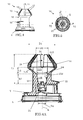
Fig. 1 a perspective front view of an upper part of an embodiment of the invention -
Fig. 2 a top view of a cap of the embodiment ofFig. 1 ; -
Fig. 3 a partially opened side view of the embodiment ofFig. 1 , showing part of the dispensing head in cross-section; -
Fig. 4 a side view of the dispensing head of the embodiment ofFig. 1 ; -
Fig. 5 a top view of a central part of the head shown inFig. 4 ; -
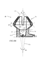
Fig. 6A a longitudinal cross-section over line VI-VI ofFig. 5 ; -
Fig. 6B a similar drawing asFig. 6A , indicating various conical planes of inner surfaces of the dispensing head; -
Fig. 7 a detail Q ofFig. 5 , showing the bottom part of the foodproduct receiving space; and -
Fig. 8 a detail ofFig. 6A , depicting the aerosol dispensing nozzle and upstream bottom part of the foodproduct receiving space. -
Figures 1-8 shown an embodiment of anaerosol container 1, to discharge and shape/model a foodproduct. The container is compact (for example with an overall volume less than 11), of a lightweight construction. Also for example, initially, a packed container, comprising the foodproduct, can weigh less than 1 kg, such as about 750 or 250 g. Preferably, the container as such is made of tinplate or aluminium, coated on the inside, and has a substantially cylindrical shape. Also, thepresent aerosol container 1 is of a non-refillable type, to be discarded after being used up. Thepresent container 1 is of a relatively inexpensive, durable construction, having few components. - The
container 1 comprises areservoir 2 containing the foodproduct, the foodproduct being safe for consumption, and a suitable propellant. As a non limiting example, the aerosol container can be packed with foodproduct and propellant, the initial pressure in the container being for example in the range of 7-18 atmospheres, depending on the amount of packed foodproduct, as will be appreciated by the skilled person. The propellant can consist of one or more gasses acceptable from the viewpoint of food technology, for example a gas which substantially dissolves in the foodproduct, a gas which substantially does not dissolve in the foodproduct and a combination of these gasses. Particularly, the propellant can comprise CO2, nitrogen (N2), laughing gas (N2O) or a combination of these gasses (such as nitrogen and laughing gas). For example, 15-25 w% (weight%) of the propellant can be N2 and the remainder of the propellant (i.e. 85-75 w%) can be N2O. - Besides, at least part of the propellant can be packed separately from the foodproduct, for example in the case that the container is provided with a movable or flexible partition to provide such separation (such as in European
patent application EP 1 061 006 A1 ). However, in a more preferred embodiment, the propellant and foodproduct are packed together, in the same reservoir, in the aerosol container. - In a particular embodiment, the foodproduct comprises cream. In that case, as will be appreciated by the skilled person, the "spray cream" that is obtained from use of the
present aerosol container 1 generally differs from conventional whipping cream (obtained from manually or automatically whipping common cream without using a cream propellant) to a high degree. Also, in the case the foodproduct comprises cream as an ingredient, the foodproduct can comprise various other ingredients, for example sugar, emulsifier, stabiliser, aroma. Preferably, the cream has a fat content in the range of about 5%-50%, for example about 40%. An other cream composition can include a fat milk constituent (particularly cream, or common cream) and a non-fat milk constituent (for example skimmed milk), seeEP 1 061 006 A1 - Referring to the drawings, the
present container 1 is also provided with operable discharge means N (partly shown inFig. 8 ) to discharge the foodproduct from thereservoir 2 into the dispensinghead 10. Preferably, the discharge means are firmly, undetachably, attached to thecontainer 1. - The
present container 1 comprises a generally mushroom shaped dispensinghead 10 defining afoodproduct receiving space 11 to receive the foodproduct from the discharge means, adistal part 15 of the head 10 (which part is located downstream, viewed in a general foodproduct flow direction, in longitudinal/axial container direction) havingfoodproduct shaping projections 12. Thepresent container 1 is configured to be used upside down, with the dispensinghead 10 substantially in a downward direction, and therefore does not comprise a dip-tube dispensing mechanism. - As an example, the foodproduct discharge means of the container can be provided with operable valve means (not depicted), comprising a downwardly (i.e. towards a container bottom) depressible foodproduct ejection nozzle N (see
Fig. 8 ) and spring means to counteract the depressing of the nozzle, such as in a currently marketed spray foodproduct aerosol container, as will be appreciated by the skilled person. For example, depressing of the foodproduct ejection nozzle N leads to opening of the valve means so that foodproduct and part of the propellant can be ejected into thefoodproduct receiving space 11 of the dispensinghead 10, to be shaped and dispensed by the dispensinghead 10. Mentioned spring means can close the valve means after the depressing of the nozzle N. Flow of foodproduct (and propellant) through the nozzle N is indicated by an arrow F inFig. 8 . - In the present embodiment, the
foodproduct dispensing head 10 is provided with an integral ring shaped connectingmember 3 which is coupled to a circumferential flange of a top part of the container. As follows fromFigures 3 ,6 and8 , an upstream part of the dispensinghead 10 comprises anozzle receiving aperture 21 to cooperate with the nozzle of thecontainer 1 . A bottom of thefoodproduct receiving area 11 of thehead 11 comprises a relatively broad first foodproduct passage extending opposite the foodproduct ejection nozzle after assembly, to receive foodproduct there-from. In the present embodiment, the first foodproduct passage is covered in an axial direction (i.e., axial with respect to a centre line L of the container 1) by afoodproduct dispersing member 23, wherein a plurality of second passages 24 (three in the present embodiment) extend through the dispersingmember 23 in lateral directions. For example, widths W of the second passages 24 (seeFig. 7 ) can be smaller than 1 mm. However, the dispensinghead 10 can also be configured in a different manner to receive foodproduct from the dispensing nozzle N, as will be appreciated by the skilled person. - In the present embodiment, the dispensing
head 10 is movably connected to the connectingmember 3, particularly tiltable about a tilting axis T (seeFig. 6 ), to depress the foodproduct ejection nozzle N of thecontainer 1. Also, thehead 10 comprises aknob part 22 for manual activation of dispensing of the foodproduct. Thus, activation of the discharge means of thecontainer 1 can be achieved by manually operating (i.e. depressing, tilting) of the dispensinghead 10. In an alternative embodiment, the foodproduct dispensing head is not movable with respect to thecontainer 1, and a dedicated operating mechanism can be provided to activate the foodproduct dispensing means. - Preferably, during the manufacturing of the
container 1, the foodproduct is first packed into thereservoir 2 via a filling aperture in the top of the container, after which the filling aperture is sealed, by assembly of the discharge means onto the container. Then, the propellant can be packed into thereservoir 2, preferably via the discharge means. In the latter case, the discharge means also serve as a filling means, to supply propellant to thereservoir 2 during the manufacture of the container. - Besides, as is shown in
Figures 1-3 , the container can be provided with acap 20, preferably of a tamper evident configuration, to cover dispensing head, wherein the discharge means and dispensing head as such are preferably not provided with a tamper-evident configuration but are directly operable after removal of the cap from the container. A tamper-evident mechanism of the cap can be configured in various ways, and can comprise a breakingmember 29 to break or rupture a tamper-evident connection between thecap 20 and a remaining part of the container, tearing means, deformation means, a one-way release or unlocking mechanism, or other suitable means. Thus, after removal of the cap, the discharge means and dispensing head can be operated in a logical and safe manner by a user, without the user needing to read a manual to understand the operation. Still, since the cap is tamper-evident, a first use of the container can be indicated and tampering of the container can be avoided. - Also, preferably, there is provided a method to manufacture the
aerosol container 1, comprising: - providing the
aerosol container 1, comprising operable discharge means, and containing a propellant and foodproduct; and - providing the
cap 20 comprising the dispensinghead 10 first (i.e., before being joined with the container). For example, thecap 20 andhead 10 can be detachably or removably interconnected, particularly by mentioned tamper evident means or in a different manner. - In that case, it is advantageous if the
cap 20 and the head 10 (i.e. thecap 20 comprising the head 10) are joined with theaerosol container 1, at the same time, such that thehead 10 can cooperate with the discharge means of thecontainer 1 after the joining of these components. Also, preferably, the cap is the a tamper-evident cap 20, having a mentioned tamper evident configuration to indicate a first removal of the cap from thecontainer 1. In that case, the tamper evident configuration can be configured, for example, to become operable by the joining of the cap/head-assembly with the container 1 (so that a subsequent removal of the cap from the container can be indicated by the tamper evident means). Also, the joining of the cap and head with the container preferably does not lead to premature activation (for example rupture) of tamper evident means. - As follows from
figures 3-8 , the dispensing head advantageously has an upstreamfoodproduct receiving part 16 having an inner surface with a diameter which widens when viewed along a foodproduct discharge direction (i.e., when viewed along the mentioned axial direction). The inner surface of the upstream head part 16 (which surface is faced towards the centre line of the head) defines a first, widening, frusco-conical foodproduct receivingspace part 11A (i.e., widening when viewed in a dispensing direction, axially away from the bottom of the foodproduct receiving space). Also, the first part 17a of the inner surface of the upstreamdispensing head part 16 extends along a virtual first conical plane (schematically indicated by dashed lines C1 inFig. 6 ). In the present embodiment, the apex angle α1 of the first conical virtual plane is in the range of 45-180 degrees, particularly in the range of 45-135 degrees degrees and more particularly 80-120. - Moreover, a second part 17b of the inner surface of the upstream
dispensing head part 16, defining at least a second (frusco-conical)part 11B of the upstream foodproduct receiving space, extends upstream with respect to the first part 17a of that surface, and extends along a virtual second conical plane. The apex angle α2 of the second conical virtual plane C2 is smaller than the apex angle α1 of the first conical plane C1, and is for example in the range of about 5-45 degrees, and particularly in the range of 10-30 degrees. In the present embodiment, the bottom of thefoodproduct receiving space 11 abuts thesecond part 11B of thatspace 11, and the mentioned secondfoodproduct dispersing passages 24 lead into the radially most narrow part of the foodproduct receiving space. - Preferably, the inner surface 15a of the
distal part 15 of the dispensing head 10 (consisting of theinner surfaces 15 of thefoodproduct shaping projections 12, in the present embodiment) substantially extends along a virtual third conical surface C3. The apex angle α3 of the third conical surface is preferably in the range of about 45-135 degrees and more preferably in the range of about 60-100 degrees, for example in the range of 70-80 degrees. For example, improved operation can be provided in the case that the apex angle α1 of a mentioned first conical surface is at least 10 degrees larger than the apex angle α3 of the third conical surface. As a non limiting example, apex angle α1 can be about 120°, apex angle α2 can be about 16° and apex angle α3 can be about 72°. - Preferably, opposite longitudinal sides of the
foodproduct shaping projections 12 abut foodproduct dispensing passages orapertures 19, thepassages 19 extending from an upstream end of an upstream contour of the widening foodproduct receiving space part. As is shown, the upstream ends of thesefoodproduct dispensing passages 19 are located at the widest part of the dispensing head (i.e., the radially widest part of the foodproduct receiving space 11), at the edge between thedistal head part 15 and the upstream wideninghead part 16. Downstream ends of thefoodproduct dispensing passages 19 join a central downstream main foodproduct discharge opening 18 of the dispensinghead 10. Also, for example, as in the drawings, the lateral diameter D2 of the main discharge opening 18 can be larger than the diameter D3 of the opposite bottom surface area of thefoodproduct receiving space 11. - Besides, in a further embodiment, a length L1 of the
foodproduct receiving space 11, measured from the upstream bottom of thatspace 1 to a downstream lateral foodproduct discharge opening 18 of the dispensing head, can be smaller than 3 cm, so that a compact and relatively hygienic dispensing head can be provided. - Also, in an embodiment, the axial length L2 of the first
upstream part 11A of thefoodproduct receiving space 11 can substantially the same as or smaller than the axial length L3 of the secondupstream part 11B of thatspace 11. As a non limiting example, the axial length L2 of the firstupstream part 11A of thatspace 11 can be in the range of 0.5-1 cm, for example about 6 mm, and the axial length L3 of the firstupstream part 11B of thatspace 11 can be in the range of 0.5-1 cm, for example about 7 mm. Moreover, as in the present embodiment, the overall length (L2+L3) of the upstream wideningfoodproduct receiving space - Besides, it has been found that, preferably, a maximum diameter D1 of the foodproduct receiving space of the dispensing head can be larger than 2 cm, or in the range of 2-3 cm.
- Besides, preferably, a minimum diameter D3 of the foodproduct receiving space (i.e. the diameter D3 of the bottom) of the dispensing head can be smaller than 1 cm, for example about 6 mm. Besides, preferably, in the present embodiment, the diameter D4 of the inner head edge extending between the first and second upstream foodproduct receiving
space part - For example, the ratio between the mentioned length of the
foodproduct receiving space 11 and the mentioned maximum diameter D1 of that space (L1:D1) can be in the range of 1:2-2:1, more specifically 1.5:2-2:1.5, for example about 1:1. - Above mentioned dimensions are examples only, but have been found to provide good results.
- In the present embodiment, when viewed in a longitudinal cross-section, inner surfaces of the foodproduct shaping portions and the inner surface of an upstream foodproduct receiving part of the dispensing head include angles β in the range of about 60-120 degrees, particularly 80-100 degrees. Thus, during operation, radially outer foodproduct parts of a discharging foodproduct can run along the inner surface of the upstream
discharge head part 16 towards thefoodproduct shaping projections 12 and intersect thefoodproduct shaping projections 12 at substantially right angles β. - During use, of the embodiment shown in the figures, the container discharge means can be operated (after having removed the cap), by pressing down the
discharge head 10. Thus, the valve means can be opened and foodproduct, preferably with some propellant, is discharged by the nozzle N into theupstream part upstream head part 16 guides the thus discharged (overrunning) foodproduct into thedistal head part 15, towards theprojections 12,intermediate apertures 19 andcentral outflow opening 18, such that the foodproduct is discharged from the head and obtains a desired shape. The present embodiment can produce a whipped foodproduct rosette (of 'spray foodproduct'), having a desired sharp relief and relatively deep foodproduct rosette grooves, in a relatively hygienic manner. - Although the illustrative embodiments of the present invention have been described in greater detail with reference to the accompanying drawings, it will be understood that the invention is not limited to those embodiments. Various changes or modifications may be effected by one skilled in the art without departing from the scope or the spirit of the invention as defined in the claims.
- It is to be understood that in the present application, the term "comprising" does not exclude other elements or steps. Also, each of the terms "a" and "an" does not exclude a plurality. Any reference sign(s) in the claims shall not be construed as limiting the scope of the claims.
- For example, the foodproduct shaping or
profiling projections 12 as well as theintermediate apertures 19 can have various shapes and dimensions, depending on the amount of profiling is desired. For example, the latterintermediate apertures 19 can have substantially constant slit widths, can be tapered or have varying widths. - Also, boundary sections between various sections of the inner surface of the dispensing head include smooth curved sections. However, as follows from the above, relatively good results are obtained in case the boundary section between the shaping
projections 12 and the upstreaminner surface 17A of the foodproduct receiving space is abrupt, for example with an angle of about 80-100 degrees, for example about 90°. - Moreover, preferably, the inner head surface at the upstream
foodproduct receiving space - Besides, it has been found that the following features a), b), c) can also provide good dispensing results, particularly independent of the feature that a maximum diameter (D1) of the foodproduct receiving space of the dispensing head is larger than about 2 cm:
- a) the feature that the inner surface (15a) of the distal part (15) of the dispensing head (10) substantially extends along a virtual third conical surface, an apex angle (α3) of the third conical surface being in the range of about 60-100 degrees;
- b) the feature that the ratio between a length (L1) of the foodproduct receiving space (11) and a maximum diameter (D1) of that space L1:D1 is in the range of 1:2-2:1, more specifically 1.5:2-2:1.5, for example about 1:1; or
- c) the feature that, when viewed in a longitudinal cross-section, inner surfaces of the foodproduct shaping portions and the inner surface of an upstream foodproduct receiving part of the dispensing head include angles (β) in the range of about 60-120 degrees, particularly 80-100 degrees.
Claims (17)
- An aerosol container (1), comprising:- a reservoir (2) containing a propellant and a foodproduct;- operable discharge means (3) to discharge the foodproduct;- a dispensing head (10) defining a foodproduct receiving space (11) to receive the foodproduct from the discharge means (3), a distal part (15) of the head (10) having foodproduct shaping projections (12),
wherein the foodproduct receiving space (11) comprises an upstream foodproduct receiving space (11A, 11B) that widens to a maximum diameter (D1), viewed in a foodproduct discharge direction, characterised in that the ratio between a length (L1) of the foodproduct receiving space (11) and the maximum diameter (D1) of that space (L1:D1) is in the range of 1:2-2:1. - The container according to claim 1, wherein said ratio is in the range of 1.5:2-2:1.5, for example about 1:1.
- The container according to any of the preceding claims, wherein the length (L1) of the foodproduct receiving space (11), measured from an upstream bottom of that space (11) to a downstream lateral foodproduct discharge opening of the dispensing head, is smaller than 3 cm.
- The container according to any of the preceding claims, wherein at least a first part (17a) of an inner surface of an upstream dispensing head part (16) defines at least a first part (11A) of the upstream foodproduct receiving space, wherein a second part (17b) of the inner surface of the upstream dispensing head part (16) defines at least a second part (11B) of the upstream foodproduct receiving space, wherein an axial length (L2) of the first upstream part (11A) of the foodproduct receiving space (11) is substantially the same as or smaller than an axial length (L3) of the second upstream part (11B) of that space (11).
- The container according to any of the preceding claims, wherein at least a first part (17a) of an inner surface of an upstream dispensing head part (16) defines at least a first part (11A) of the upstream foodproduct receiving space, wherein a second part (17b) of the inner surface of the upstream dispensing head part (16) defines at least a second part (11B) of the upstream foodproduct receiving space, wherein the axial length (L2) of the first upstream part (11A) of the foodproduct receiving space (11) is in the range of 0.5-1 cm, for example about 6 mm, wherein the axial length (L3) of the second upstream part (11B) of that space (11) is in the range of 0.5-1 cm, for example about 7 mm.
- The container according to claim 4 or 5, wherein the overall length (L2+L3) of the upstream widening foodproduct receiving space (11A, 11B) is larger than at least half the overall length (L1) of the foodproduct receiving space 11.
- The container according to any of the preceding claims, wherein at least a first part (17a) of an inner surface of an upstream dispensing head part (16), defining at least a first part (11A) of the upstream foodproduct receiving space, extends along a virtual first conical plane, , wherein the apex angle (α1) of the first conical virtual plane is in the range of 45-180 degrees, particularly in the range of 80-120 degrees.
- The container according to claim 7, wherein a second part (17b) of the inner surface of the upstream dispensing head part (16), defining at least a second part (11B) of the upstream foodproduct receiving space, extends upstream with respect to the first part (17a) of that surface, and extends along a virtual second conical plane, wherein the apex angle (α2) of the second conical virtual plane is smaller than the apex angle (α1) of the first conical plane, and is for example in the range of about 5-45 degrees, and particularly in the range of 10-30 degrees.
- The container according to any of the preceding claims, wherein the inner surface (15a) of the distal part (15) of the dispensing head (10) substantially extends along a virtual third conical surface, an apex angle (α3) of the third conical surface preferably being in the range of about 45-135 degrees and more preferably in the range of about 60-100 degrees.
- The container according to any of the preceding claims, wherein opposite longitudinal sides of the foodproduct shaping projections (12) abut foodproduct dispensing apertures (19), the apertures extending from an upstream end of an upstream contour of the widening foodproduct receiving space part.
- The container according to any of the preceding claims, wherein a minimum diameter (D3) of the foodproduct receiving space (11) of the dispensing head is smaller than 1 cm, for example about 6 mm.
- The container according to any of the preceding claims, wherein a lateral diameter (D2) of a main discharge opening (18) of the dispensing head (10) is larger than a diameter (D3) of an opposite bottom surface area of the foodproduct receiving space (11).
- The container according to any of the preceding claims, wherein the dispensing head (10) is provided with an integral ring shaped connecting member (3) which is coupled to a circumferential flange of a top part of the container (1).
- The container according to claim 13, wherein the dispensing head (10) is tiltably connected to the connecting member 3, about a tilting axis (T), to depress a foodproduct ejection nozzle (N) of the container (1), wherein the head (10) comprises a knob part (22) for manual activation of dispensing of the foodproduct.
- An aerosol container (1), for example a container according to any of the preceding claims, comprising:- a reservoir (2) containing a propellant and a foodproduct;- operable discharge means (3) to discharge the foodproduct;- a dispensing head (10) defining a foodproduct receiving space (11) to receive the foodproduct from the discharge means (3), a distal part (15) of the head (10) having foodproduct shaping projections (12),
characterised in that the foodproduct receiving space (11) comprises an upstream foodproduct receiving space (11A, 11B) that widens, viewed in a foodproduct discharge direction, wherein the length (L1) of the foodproduct receiving space (11), measured from an upstream bottom of that space (11) to a downstream lateral foodproduct discharge opening of the dispensing head, is smaller than 3 cm. - Method to manufacture an aerosol container according to any of the preceding claims, wherein the method comprises:- providing a cap (20) comprising a dispensing head (10), the cap (20) covering the head (10);- providing an aerosol container (1) comprising operable discharge means, the container (1) containing a propellant and a foodproduct; and- joining the cap (20) together with the head (10) with the aerosol container (1), such that the head (10) can cooperate with the discharge means of the container (1), , wherein the cap is a tamper-evident cap (20), having a tamper evident configuration to indicate a first removal of the cap from the container (1).
- A dispensing head of a container according to any of claims 1-15.
Priority Applications (9)
| Application Number | Priority Date | Filing Date | Title |
|---|---|---|---|
| SI200631504T SI2218655T1 (en) | 2006-09-11 | 2006-09-11 | Aerosol container |
| DK10181861.5T DK2295339T3 (en) | 2006-09-11 | 2006-09-11 | Pressurized |
| AT10181861T ATE550268T1 (en) | 2006-09-11 | 2006-09-11 | AEROSOL CONTAINERS |
| DK10165241.0T DK2218655T3 (en) | 2006-09-11 | 2006-09-11 | Pressurized |
| EP10181861A EP2295339B1 (en) | 2006-09-11 | 2006-09-11 | Aerosol container |
| PL10181861T PL2295339T3 (en) | 2006-09-11 | 2006-09-11 | Aerosol can |
| PL10165241T PL2218655T3 (en) | 2006-09-11 | 2006-09-11 | Aerosol can |
| CY20121100527T CY1112856T1 (en) | 2006-09-11 | 2012-06-11 | PRESSURE GAS PIPELINE |
| CY20131100032T CY1113536T1 (en) | 2006-09-11 | 2013-01-11 | PRESSURE GAS PIPELINE |
Applications Claiming Priority (2)
| Application Number | Priority Date | Filing Date | Title |
|---|---|---|---|
| PCT/NL2006/000448 WO2008033005A1 (en) | 2006-09-11 | 2006-09-11 | Aerosol container |
| EP06799454A EP1916931B1 (en) | 2006-09-11 | 2006-09-11 | Aerosol container |
Related Parent Applications (2)
| Application Number | Title | Priority Date | Filing Date |
|---|---|---|---|
| EP06799454A Division EP1916931B1 (en) | 2006-09-11 | 2006-09-11 | Aerosol container |
| EP06799454.1 Division | 2006-09-11 |
Related Child Applications (1)
| Application Number | Title | Priority Date | Filing Date |
|---|---|---|---|
| EP10181861A Division-Into EP2295339B1 (en) | 2006-09-11 | 2006-09-11 | Aerosol container |
Publications (2)
| Publication Number | Publication Date |
|---|---|
| EP2218655A1 true EP2218655A1 (en) | 2010-08-18 |
| EP2218655B1 EP2218655B1 (en) | 2012-10-17 |
Family
ID=37954002
Family Applications (3)
| Application Number | Title | Priority Date | Filing Date |
|---|---|---|---|
| EP06799454A Active EP1916931B1 (en) | 2006-09-11 | 2006-09-11 | Aerosol container |
| EP10165241A Active EP2218655B1 (en) | 2006-09-11 | 2006-09-11 | Aerosol container |
| EP10181861A Active EP2295339B1 (en) | 2006-09-11 | 2006-09-11 | Aerosol container |
Family Applications Before (1)
| Application Number | Title | Priority Date | Filing Date |
|---|---|---|---|
| EP06799454A Active EP1916931B1 (en) | 2006-09-11 | 2006-09-11 | Aerosol container |
Family Applications After (1)
| Application Number | Title | Priority Date | Filing Date |
|---|---|---|---|
| EP10181861A Active EP2295339B1 (en) | 2006-09-11 | 2006-09-11 | Aerosol container |
Country Status (11)
| Country | Link |
|---|---|
| US (4) | US8419411B2 (en) |
| EP (3) | EP1916931B1 (en) |
| AT (2) | ATE550268T1 (en) |
| CY (3) | CY1111929T1 (en) |
| DE (1) | DE602006015200D1 (en) |
| DK (3) | DK2218655T3 (en) |
| ES (3) | ES2347882T3 (en) |
| PL (3) | PL1916931T3 (en) |
| PT (3) | PT2218655E (en) |
| SI (1) | SI1916931T1 (en) |
| WO (1) | WO2008033005A1 (en) |
Families Citing this family (20)
| Publication number | Priority date | Publication date | Assignee | Title |
|---|---|---|---|---|
| JP4962690B2 (en) * | 2005-10-31 | 2012-06-27 | ザ プロクター アンド ギャンブル カンパニー | Pouring cap |
| ATE550268T1 (en) * | 2006-09-11 | 2012-04-15 | Friesland Brands Bv | AEROSOL CONTAINERS |
| NL2002949C2 (en) * | 2009-06-02 | 2010-12-07 | Friesland Brands Bv | An assembly for dispensing a product. |
| NL2003782C2 (en) | 2009-11-10 | 2011-05-11 | Friesland Brands Bv | Aerosol container. |
| US10625930B2 (en) * | 2016-01-29 | 2020-04-21 | Daizo Corporation | Ejection member and aerosol product using same |
| BE1024437B9 (en) | 2016-10-24 | 2018-06-06 | Giuseppe Pascariello | Universal device for the active cooling or heating and distribution of food from aerosol cans |
| CN111356534A (en) | 2017-11-17 | 2020-06-30 | 弗里斯兰康必奶荷兰有限公司 | Apparatus and method for dispensing and foaming of products |
| EP3513880B1 (en) | 2018-01-23 | 2021-08-25 | The Procter & Gamble Company | Dispensing device suitable for a foamable product |
| USD958657S1 (en) * | 2018-03-05 | 2022-07-26 | Clayton Corporation | Dispensing gun for dispensing flowable product from a pressurized can |
| CN110466896A (en) * | 2018-05-09 | 2019-11-19 | 以清商贸(上海)有限公司 | A mousse spray can |
| CN110466895A (en) * | 2018-05-09 | 2019-11-19 | 以清商贸(上海)有限公司 | A kind of beverage aerosol can |
| US11267644B2 (en) * | 2018-11-08 | 2022-03-08 | The Procter And Gamble Company | Aerosol foam dispenser and methods for delivering a textured foam product |
| WO2020168150A1 (en) * | 2019-02-14 | 2020-08-20 | Conagra Foods Rdm, Inc. | Formulation and dispenser systems for beverage foam toppings |
| JP2020179870A (en) * | 2019-04-24 | 2020-11-05 | 花王株式会社 | Foam discharger |
| US11090666B1 (en) | 2020-01-29 | 2021-08-17 | Over the Top Foods, Inc. | Dispensation devices and methods of manufacture and use thereof |
| US11172787B2 (en) | 2020-03-04 | 2021-11-16 | Summit Packaging Systems, Inc. | Food product dispenser valve normally biased into closed position |
| KR102581495B1 (en) * | 2020-12-30 | 2023-09-25 | 주식회사 지엔비아이앤씨 | Nitro Beverage Container |
| WO2022250534A1 (en) * | 2021-05-27 | 2022-12-01 | Frieslandcampina Nederland B.V. | An aerosol container containing food product |
| IT202100015020A1 (en) * | 2021-06-09 | 2022-12-09 | Iffco Italia S R L | IMPROVED AEROSOL CREAM DISPENSER |
| WO2023218045A1 (en) | 2022-05-12 | 2023-11-16 | Kerry Group Services International Limited | Edible emulsions for air-filled foams |
Citations (5)
| Publication number | Priority date | Publication date | Assignee | Title |
|---|---|---|---|---|
| US3263744A (en) * | 1965-03-08 | 1966-08-02 | Graeme J Mackeown | Shave cream heaters |
| FR2281287A1 (en) * | 1974-08-05 | 1976-03-05 | Valois | SAFETY CAP FOR AEROSOL BOTTLE |
| DE7527199U (en) * | 1975-08-28 | 1976-04-22 | F. Vaihinger Gmbh Maschinen- Und Armaturenbau, 6054 Juegesheim | Removal device for whipped cream machines |
| EP1061006A1 (en) | 1999-06-16 | 2000-12-20 | Friesland Brands B.V. | Aerosol system for cream or an aerated dessert |
| US20050193744A1 (en) * | 2004-03-03 | 2005-09-08 | Good Humor-Breyers Ice Cream, Division Of Conopco, Inc. | Frozen aerated product in a container and a valve for dispensing such |
Family Cites Families (27)
| Publication number | Priority date | Publication date | Assignee | Title |
|---|---|---|---|---|
| DE26686C (en) | A. OPESSI in Turin | Innovations to Centisimal weighbridges without interrupting the track | ||
| US2892575A (en) * | 1956-03-29 | 1959-06-30 | Super Whip Valve Co | Dispenser valve structure |
| US2957610A (en) | 1958-03-21 | 1960-10-25 | Michel David Daniel | Dispensing apparatus |
| US2975944A (en) | 1958-06-04 | 1961-03-21 | Michel David Daniel | Foam valve assembly |
| US3350159A (en) * | 1965-07-12 | 1967-10-31 | Jr Robert C Rice | Aerosol shaving cream dispenser and applicator |
| US3415426A (en) * | 1966-05-16 | 1968-12-10 | Eaton Yale & Towne | Dispensing valve |
| US3447779A (en) * | 1967-08-04 | 1969-06-03 | Clayton Corp | Sanitary valve and nozzle assembly for pressure dispensers |
| US3606266A (en) * | 1968-12-31 | 1971-09-20 | John Macmanus | Machine for producing aerated toppings |
| US3722760A (en) * | 1971-12-23 | 1973-03-27 | Clayton Corp | Dispensing valve having positive tilt stem |
| IT981888B (en) | 1973-04-06 | 1974-10-10 | Gimas Srl | DISPENSING AND SAFETY VALVE FOR BOTTLES FOR WHITED CREAM |
| IT1076650B (en) | 1977-03-31 | 1985-04-27 | Massarani Giuliano | DISPENSING VALVE FOR WHIPPED CREAM |
| IT7921092V0 (en) * | 1979-03-15 | 1979-03-15 | Adm Spa | LID DISPENSER UNIT FOR PRESSURIZED CONTAINERS. |
| DE3419736C2 (en) | 1984-05-26 | 1986-11-06 | Heimsyphon GmbH, 5650 Solingen | Dispensing and safety valve for a cream siphon |
| FR2567423B1 (en) | 1984-07-11 | 1987-04-03 | Aerosol Inventions Dev | RINSABLE DIFFUSER FOR AEROSOL PACKAGING VALVE |
| FR2570000A1 (en) * | 1984-09-12 | 1986-03-14 | Valve Precision Sarl | Plastic spraying (diffusing) device for a pressurised container |
| FR2598101B1 (en) | 1986-04-30 | 1988-08-05 | Oreal | NOZZLE FOR DISPENSING A FOAMING PRODUCT |
| US5553755A (en) * | 1995-06-09 | 1996-09-10 | Summit Packaging Systems, Inc. | Whipped cream dispenser |
| FR2742736B1 (en) | 1995-12-22 | 1998-01-16 | Oreal | LIQUID DISPENSER INCLUDING A PUSH BUTTON |
| NZ331799A (en) | 1996-02-22 | 2000-03-27 | Sealed Air Corp | An absorbent pad having on face containing a lamination of microperforated sheets |
| DE19607691A1 (en) | 1996-02-29 | 1997-09-04 | Coster Tecnologie Speciali Spa | Foam head |
| NL1002559C2 (en) | 1996-03-08 | 1997-09-09 | Menken Dairy Food B V | Aerosol for dispensing a concentrate for preparing a milkshake. |
| EP0913340A1 (en) | 1997-09-24 | 1999-05-06 | Societe Des Produits Nestle S.A. | Package with milk or milk replacement product |
| US6607106B2 (en) | 2001-07-09 | 2003-08-19 | Conagra Dairy Food Research Center | Aerosol valve |
| AT411171B (en) | 2001-11-06 | 2003-10-27 | Isi Gmbh | CONTAINER FOR PRODUCING AND STORING EMULSIBLE FOODSTUFFS |
| HU227136B1 (en) | 2002-12-12 | 2010-08-30 | Liss Patrongyarto | Siphon head for whipped cream siphon |
| DE202006003701U1 (en) | 2006-03-09 | 2006-07-06 | Hochwald Nahrungsmittel-Werke Gmbh | Spraying nozzle for foam product e.g. spray cream, has discharging pipe with circular discharge end that is uniformly formed, and window-like two-way opening formed in interior of standpipe of spraying attachment |
| ATE550268T1 (en) * | 2006-09-11 | 2012-04-15 | Friesland Brands Bv | AEROSOL CONTAINERS |
-
2006
- 2006-09-11 AT AT10181861T patent/ATE550268T1/en active
- 2006-09-11 US US12/440,674 patent/US8419411B2/en not_active Expired - Fee Related
- 2006-09-11 EP EP06799454A patent/EP1916931B1/en active Active
- 2006-09-11 DK DK10165241.0T patent/DK2218655T3/en active
- 2006-09-11 EP EP10165241A patent/EP2218655B1/en active Active
- 2006-09-11 DK DK10181861.5T patent/DK2295339T3/en active
- 2006-09-11 PT PT101652410T patent/PT2218655E/en unknown
- 2006-09-11 SI SI200630792T patent/SI1916931T1/en unknown
- 2006-09-11 PL PL06799454T patent/PL1916931T3/en unknown
- 2006-09-11 ES ES06799454T patent/ES2347882T3/en active Active
- 2006-09-11 PL PL10181861T patent/PL2295339T3/en unknown
- 2006-09-11 ES ES10165241T patent/ES2397783T3/en active Active
- 2006-09-11 DE DE602006015200T patent/DE602006015200D1/en active Active
- 2006-09-11 AT AT06799454T patent/ATE472283T1/en active
- 2006-09-11 ES ES10181861T patent/ES2383508T3/en active Active
- 2006-09-11 PT PT06799454T patent/PT1916931E/en unknown
- 2006-09-11 WO PCT/NL2006/000448 patent/WO2008033005A1/en not_active Ceased
- 2006-09-11 DK DK06799454.1T patent/DK1916931T3/en active
- 2006-09-11 EP EP10181861A patent/EP2295339B1/en active Active
- 2006-09-11 PL PL10165241T patent/PL2218655T3/en unknown
- 2006-09-11 PT PT10181861T patent/PT2295339E/en unknown
-
2010
- 2010-09-03 CY CY20101100811T patent/CY1111929T1/en unknown
-
2012
- 2012-06-11 CY CY20121100527T patent/CY1112856T1/en unknown
-
2013
- 2013-01-11 CY CY20131100032T patent/CY1113536T1/en unknown
- 2013-03-22 US US13/849,311 patent/US9650200B2/en not_active Expired - Fee Related
-
2017
- 2017-04-11 US US15/484,968 patent/US10227173B2/en active Active
-
2019
- 2019-02-13 US US16/275,119 patent/US11440727B2/en active Active
Patent Citations (5)
| Publication number | Priority date | Publication date | Assignee | Title |
|---|---|---|---|---|
| US3263744A (en) * | 1965-03-08 | 1966-08-02 | Graeme J Mackeown | Shave cream heaters |
| FR2281287A1 (en) * | 1974-08-05 | 1976-03-05 | Valois | SAFETY CAP FOR AEROSOL BOTTLE |
| DE7527199U (en) * | 1975-08-28 | 1976-04-22 | F. Vaihinger Gmbh Maschinen- Und Armaturenbau, 6054 Juegesheim | Removal device for whipped cream machines |
| EP1061006A1 (en) | 1999-06-16 | 2000-12-20 | Friesland Brands B.V. | Aerosol system for cream or an aerated dessert |
| US20050193744A1 (en) * | 2004-03-03 | 2005-09-08 | Good Humor-Breyers Ice Cream, Division Of Conopco, Inc. | Frozen aerated product in a container and a valve for dispensing such |
Also Published As
| Publication number | Publication date |
|---|---|
| EP1916931A1 (en) | 2008-05-07 |
| EP1916931B1 (en) | 2010-06-30 |
| CY1113536T1 (en) | 2016-06-22 |
| ES2347882T3 (en) | 2010-11-22 |
| CY1112856T1 (en) | 2016-04-13 |
| PL1916931T3 (en) | 2011-04-29 |
| SI1916931T1 (en) | 2010-11-30 |
| DK2218655T3 (en) | 2013-02-04 |
| US20170217665A1 (en) | 2017-08-03 |
| DK2295339T3 (en) | 2012-07-02 |
| ES2383508T3 (en) | 2012-06-21 |
| PT2218655E (en) | 2013-01-25 |
| US20100062096A1 (en) | 2010-03-11 |
| CY1111929T1 (en) | 2015-11-04 |
| ATE472283T1 (en) | 2010-07-15 |
| PT1916931E (en) | 2010-09-23 |
| US9650200B2 (en) | 2017-05-16 |
| DE602006015200D1 (en) | 2010-08-12 |
| ATE550268T1 (en) | 2012-04-15 |
| PT2295339E (en) | 2012-06-21 |
| DK1916931T3 (en) | 2010-10-04 |
| WO2008033005A1 (en) | 2008-03-20 |
| US10227173B2 (en) | 2019-03-12 |
| EP2295339A1 (en) | 2011-03-16 |
| US20140054328A1 (en) | 2014-02-27 |
| EP2218655B1 (en) | 2012-10-17 |
| EP2295339B1 (en) | 2012-03-21 |
| US8419411B2 (en) | 2013-04-16 |
| US20190177075A1 (en) | 2019-06-13 |
| PL2295339T3 (en) | 2012-08-31 |
| PL2218655T3 (en) | 2013-03-29 |
| US11440727B2 (en) | 2022-09-13 |
| ES2397783T3 (en) | 2013-03-11 |
Similar Documents
| Publication | Publication Date | Title |
|---|---|---|
| US11440727B2 (en) | Aerosol container | |
| EP3409618B1 (en) | Ejection member and aerosol product using same | |
| US6730339B2 (en) | Lollipop with fluid reservoir handle | |
| EP1397960B1 (en) | Lollipop with fluid reservoir handle and method of making the same | |
| JP7157562B6 (en) | Dispensing components and dispensing products | |
| EP4347432B1 (en) | An aerosol container containing food product | |
| US3447779A (en) | Sanitary valve and nozzle assembly for pressure dispensers | |
| EP3009377B1 (en) | An assembly for dispensing a product | |
| JP7060947B2 (en) | Discharge members and aerosol products | |
| NL2003782C2 (en) | Aerosol container. | |
| JPH05184422A (en) | Dispensing method for dispensing viscous gel and dispensing apparatus for carrying out this dispensing method | |
| CN111372868A (en) | Spray nozzle and aerosol product for foamable contents |
Legal Events
| Date | Code | Title | Description |
|---|---|---|---|
| PUAI | Public reference made under article 153(3) epc to a published international application that has entered the european phase |
Free format text: ORIGINAL CODE: 0009012 |
|
| 17P | Request for examination filed |
Effective date: 20100608 |
|
| AC | Divisional application: reference to earlier application |
Ref document number: 1916931 Country of ref document: EP Kind code of ref document: P |
|
| AK | Designated contracting states |
Kind code of ref document: A1 Designated state(s): AT BE BG CH CY CZ DE DK EE ES FI FR GB GR HU IE IS IT LI LT LU LV MC NL PL PT RO SE SI SK TR |
|
| RAP1 | Party data changed (applicant data changed or rights of an application transferred) |
Owner name: FRIESLAND BRANDS B.V. |
|
| 17Q | First examination report despatched |
Effective date: 20110525 |
|
| GRAP | Despatch of communication of intention to grant a patent |
Free format text: ORIGINAL CODE: EPIDOSNIGR1 |
|
| GRAS | Grant fee paid |
Free format text: ORIGINAL CODE: EPIDOSNIGR3 |
|
| GRAA | (expected) grant |
Free format text: ORIGINAL CODE: 0009210 |
|
| AC | Divisional application: reference to earlier application |
Ref document number: 1916931 Country of ref document: EP Kind code of ref document: P |
|
| AK | Designated contracting states |
Kind code of ref document: B1 Designated state(s): AT BE BG CH CY CZ DE DK EE ES FI FR GB GR HU IE IS IT LI LT LU LV MC NL PL PT RO SE SI SK TR |
|
| REG | Reference to a national code |
Ref country code: GB Ref legal event code: FG4D |
|
| REG | Reference to a national code |
Ref country code: CH Ref legal event code: EP |
|
| REG | Reference to a national code |
Ref country code: IE Ref legal event code: FG4D |
|
| REG | Reference to a national code |
Ref country code: AT Ref legal event code: REF Ref document number: 579801 Country of ref document: AT Kind code of ref document: T Effective date: 20121115 |
|
| REG | Reference to a national code |
Ref country code: DE Ref legal event code: R096 Ref document number: 602006032579 Country of ref document: DE Effective date: 20121213 |
|
| REG | Reference to a national code |
Ref country code: SE Ref legal event code: TRGR |
|
| REG | Reference to a national code |
Ref country code: RO Ref legal event code: EPE |
|
| REG | Reference to a national code |
Ref country code: PT Ref legal event code: SC4A Free format text: AVAILABILITY OF NATIONAL TRANSLATION Effective date: 20130115 |
|
| REG | Reference to a national code |
Ref country code: DK Ref legal event code: T3 |
|
| REG | Reference to a national code |
Ref country code: EE Ref legal event code: FG4A Ref document number: E007361 Country of ref document: EE Effective date: 20121120 |
|
| REG | Reference to a national code |
Ref country code: NL Ref legal event code: T3 |
|
| REG | Reference to a national code |
Ref country code: ES Ref legal event code: FG2A Ref document number: 2397783 Country of ref document: ES Kind code of ref document: T3 Effective date: 20130311 |
|
| REG | Reference to a national code |
Ref country code: PL Ref legal event code: T3 Ref country code: GR Ref legal event code: EP Ref document number: 20130400052 Country of ref document: GR Effective date: 20130225 |
|
| REG | Reference to a national code |
Ref country code: SK Ref legal event code: T3 Ref document number: E 13214 Country of ref document: SK |
|
| PLBE | No opposition filed within time limit |
Free format text: ORIGINAL CODE: 0009261 |
|
| STAA | Information on the status of an ep patent application or granted ep patent |
Free format text: STATUS: NO OPPOSITION FILED WITHIN TIME LIMIT |
|
| 26N | No opposition filed |
Effective date: 20130718 |
|
| REG | Reference to a national code |
Ref country code: HU Ref legal event code: AG4A Ref document number: E016602 Country of ref document: HU |
|
| PGFP | Annual fee paid to national office [announced via postgrant information from national office to epo] |
Ref country code: MC Payment date: 20130911 Year of fee payment: 8 |
|
| REG | Reference to a national code |
Ref country code: DE Ref legal event code: R097 Ref document number: 602006032579 Country of ref document: DE Effective date: 20130718 |
|
| REG | Reference to a national code |
Ref country code: CH Ref legal event code: PCAR Free format text: NEW ADDRESS: EIGERSTRASSE 2 POSTFACH, 3000 BERN 14 (CH) |
|
| PG25 | Lapsed in a contracting state [announced via postgrant information from national office to epo] |
Ref country code: MC Free format text: LAPSE BECAUSE OF NON-PAYMENT OF DUE FEES Effective date: 20140930 |
|
| REG | Reference to a national code |
Ref country code: DE Ref legal event code: R082 Ref document number: 602006032579 Country of ref document: DE Representative=s name: HOFFMANN - EITLE PATENT- UND RECHTSANWAELTE PA, DE Ref country code: DE Ref legal event code: R081 Ref document number: 602006032579 Country of ref document: DE Owner name: FRIESLANDCAMPINA NEDERLAND B.V., NL Free format text: FORMER OWNER: FRIESLAND BRANDS B.V., AMERSFOORT, NL |
|
| REG | Reference to a national code |
Ref country code: FR Ref legal event code: PLFP Year of fee payment: 11 |
|
| PGFP | Annual fee paid to national office [announced via postgrant information from national office to epo] |
Ref country code: IE Payment date: 20160923 Year of fee payment: 11 Ref country code: BG Payment date: 20160915 Year of fee payment: 11 Ref country code: IS Payment date: 20160912 Year of fee payment: 11 Ref country code: CH Payment date: 20160920 Year of fee payment: 11 Ref country code: FI Payment date: 20160913 Year of fee payment: 11 Ref country code: EE Payment date: 20160914 Year of fee payment: 11 Ref country code: LT Payment date: 20160823 Year of fee payment: 11 |
|
| PGFP | Annual fee paid to national office [announced via postgrant information from national office to epo] |
Ref country code: SI Payment date: 20160826 Year of fee payment: 11 Ref country code: LV Payment date: 20160913 Year of fee payment: 11 Ref country code: RO Payment date: 20160824 Year of fee payment: 11 |
|
| REG | Reference to a national code |
Ref country code: DE Ref legal event code: R008 Ref document number: 602006032579 Country of ref document: DE Ref country code: DE Ref legal event code: R039 Ref document number: 602006032579 Country of ref document: DE |
|
| PGFP | Annual fee paid to national office [announced via postgrant information from national office to epo] |
Ref country code: TR Payment date: 20160824 Year of fee payment: 11 Ref country code: LU Payment date: 20161005 Year of fee payment: 11 |
|
| PGFP | Annual fee paid to national office [announced via postgrant information from national office to epo] |
Ref country code: CY Payment date: 20160825 Year of fee payment: 11 |
|
| REG | Reference to a national code |
Ref country code: FR Ref legal event code: PLFP Year of fee payment: 12 |
|
| REG | Reference to a national code |
Ref country code: LT Ref legal event code: MM4D Effective date: 20170911 |
|
| REG | Reference to a national code |
Ref country code: DE Ref legal event code: R040 Ref document number: 602006032579 Country of ref document: DE |
|
| REG | Reference to a national code |
Ref country code: EE Ref legal event code: MM4A Ref document number: E007361 Country of ref document: EE Effective date: 20170930 |
|
| PG25 | Lapsed in a contracting state [announced via postgrant information from national office to epo] |
Ref country code: RO Free format text: LAPSE BECAUSE OF NON-PAYMENT OF DUE FEES Effective date: 20170911 Ref country code: LT Free format text: LAPSE BECAUSE OF NON-PAYMENT OF DUE FEES Effective date: 20170911 Ref country code: CY Free format text: LAPSE BECAUSE OF NON-PAYMENT OF DUE FEES Effective date: 20170911 Ref country code: FI Free format text: LAPSE BECAUSE OF NON-PAYMENT OF DUE FEES Effective date: 20170911 |
|
| REG | Reference to a national code |
Ref country code: CH Ref legal event code: PL |
|
| PG25 | Lapsed in a contracting state [announced via postgrant information from national office to epo] |
Ref country code: LV Free format text: LAPSE BECAUSE OF NON-PAYMENT OF DUE FEES Effective date: 20170911 |
|
| REG | Reference to a national code |
Ref country code: IE Ref legal event code: MM4A |
|
| PG25 | Lapsed in a contracting state [announced via postgrant information from national office to epo] |
Ref country code: LU Free format text: LAPSE BECAUSE OF NON-PAYMENT OF DUE FEES Effective date: 20170911 |
|
| REG | Reference to a national code |
Ref country code: SI Ref legal event code: KO00 Effective date: 20180508 |
|
| PG25 | Lapsed in a contracting state [announced via postgrant information from national office to epo] |
Ref country code: IE Free format text: LAPSE BECAUSE OF NON-PAYMENT OF DUE FEES Effective date: 20170911 Ref country code: CH Free format text: LAPSE BECAUSE OF NON-PAYMENT OF DUE FEES Effective date: 20170930 Ref country code: LI Free format text: LAPSE BECAUSE OF NON-PAYMENT OF DUE FEES Effective date: 20170930 Ref country code: EE Free format text: LAPSE BECAUSE OF NON-PAYMENT OF DUE FEES Effective date: 20170930 |
|
| PG25 | Lapsed in a contracting state [announced via postgrant information from national office to epo] |
Ref country code: SI Free format text: LAPSE BECAUSE OF NON-PAYMENT OF DUE FEES Effective date: 20170912 |
|
| REG | Reference to a national code |
Ref country code: FR Ref legal event code: PLFP Year of fee payment: 13 |
|
| PG25 | Lapsed in a contracting state [announced via postgrant information from national office to epo] |
Ref country code: BG Free format text: LAPSE BECAUSE OF NON-PAYMENT OF DUE FEES Effective date: 20180405 |
|
| REG | Reference to a national code |
Ref country code: BE Ref legal event code: MF Free format text: REGISTRATION OF INVALIDITY DECLARATION FINAL DECISION, TOTAL ANNULMENT Effective date: 20190628 |
|
| PG25 | Lapsed in a contracting state [announced via postgrant information from national office to epo] |
Ref country code: BE Free format text: THE PATENT HAS BEEN ANNULLED BY A DECISION OF A NATIONAL AUTHORITY Effective date: 20190628 |
|
| PG25 | Lapsed in a contracting state [announced via postgrant information from national office to epo] |
Ref country code: IS Free format text: LAPSE BECAUSE OF NON-PAYMENT OF DUE FEES Effective date: 20171001 |
|
| PG25 | Lapsed in a contracting state [announced via postgrant information from national office to epo] |
Ref country code: TR Free format text: LAPSE BECAUSE OF NON-PAYMENT OF DUE FEES Effective date: 20170911 |
|
| P01 | Opt-out of the competence of the unified patent court (upc) registered |
Effective date: 20230512 |
|
| PGFP | Annual fee paid to national office [announced via postgrant information from national office to epo] |
Ref country code: GR Payment date: 20240923 Year of fee payment: 19 Ref country code: DK Payment date: 20240923 Year of fee payment: 19 |
|
| PGFP | Annual fee paid to national office [announced via postgrant information from national office to epo] |
Ref country code: PT Payment date: 20240829 Year of fee payment: 19 |
|
| PGFP | Annual fee paid to national office [announced via postgrant information from national office to epo] |
Ref country code: NL Payment date: 20240918 Year of fee payment: 19 |
|
| PGFP | Annual fee paid to national office [announced via postgrant information from national office to epo] |
Ref country code: CZ Payment date: 20240903 Year of fee payment: 19 |
|
| PGFP | Annual fee paid to national office [announced via postgrant information from national office to epo] |
Ref country code: AT Payment date: 20240919 Year of fee payment: 19 |
|
| PGFP | Annual fee paid to national office [announced via postgrant information from national office to epo] |
Ref country code: PL Payment date: 20240830 Year of fee payment: 19 |
|
| PGFP | Annual fee paid to national office [announced via postgrant information from national office to epo] |
Ref country code: HU Payment date: 20240920 Year of fee payment: 19 |
|
| PGFP | Annual fee paid to national office [announced via postgrant information from national office to epo] |
Ref country code: SE Payment date: 20240919 Year of fee payment: 19 |
|
| PGFP | Annual fee paid to national office [announced via postgrant information from national office to epo] |
Ref country code: DE Payment date: 20250919 Year of fee payment: 20 |
|
| PGFP | Annual fee paid to national office [announced via postgrant information from national office to epo] |
Ref country code: IT Payment date: 20250923 Year of fee payment: 20 |
|
| PGFP | Annual fee paid to national office [announced via postgrant information from national office to epo] |
Ref country code: GB Payment date: 20250918 Year of fee payment: 20 |
|
| PGFP | Annual fee paid to national office [announced via postgrant information from national office to epo] |
Ref country code: FR Payment date: 20250919 Year of fee payment: 20 |
|
| PGFP | Annual fee paid to national office [announced via postgrant information from national office to epo] |
Ref country code: SK Payment date: 20250903 Year of fee payment: 20 |
|
| PGFP | Annual fee paid to national office [announced via postgrant information from national office to epo] |
Ref country code: ES Payment date: 20251028 Year of fee payment: 20 |
|
| REG | Reference to a national code |
Ref country code: DK Ref legal event code: EBP Effective date: 20250930 |