EP2218885B1 - Dispositif de chapeau de pluie pour équipement lourd de construction - Google Patents
Dispositif de chapeau de pluie pour équipement lourd de construction Download PDFInfo
- Publication number
- EP2218885B1 EP2218885B1 EP10152904.8A EP10152904A EP2218885B1 EP 2218885 B1 EP2218885 B1 EP 2218885B1 EP 10152904 A EP10152904 A EP 10152904A EP 2218885 B1 EP2218885 B1 EP 2218885B1
- Authority
- EP
- European Patent Office
- Prior art keywords
- exhaust gas
- fixing shaft
- discharging port
- distal end
- end portion
- Prior art date
- Legal status (The legal status is an assumption and is not a legal conclusion. Google has not performed a legal analysis and makes no representation as to the accuracy of the status listed.)
- Active
Links
Images




Classifications
-
- E—FIXED CONSTRUCTIONS
- E02—HYDRAULIC ENGINEERING; FOUNDATIONS; SOIL SHIFTING
- E02F—DREDGING; SOIL-SHIFTING
- E02F9/00—Component parts of dredgers or soil-shifting machines, not restricted to one of the kinds covered by groups E02F3/00 - E02F7/00
-
- F—MECHANICAL ENGINEERING; LIGHTING; HEATING; WEAPONS; BLASTING
- F01—MACHINES OR ENGINES IN GENERAL; ENGINE PLANTS IN GENERAL; STEAM ENGINES
- F01N—GAS-FLOW SILENCERS OR EXHAUST APPARATUS FOR MACHINES OR ENGINES IN GENERAL; GAS-FLOW SILENCERS OR EXHAUST APPARATUS FOR INTERNAL-COMBUSTION ENGINES
- F01N13/00—Exhaust or silencing apparatus characterised by constructional features
- F01N13/08—Other arrangements or adaptations of exhaust conduits
- F01N13/085—Other arrangements or adaptations of exhaust conduits having means preventing foreign matter from entering exhaust conduit
-
- F—MECHANICAL ENGINEERING; LIGHTING; HEATING; WEAPONS; BLASTING
- F01—MACHINES OR ENGINES IN GENERAL; ENGINE PLANTS IN GENERAL; STEAM ENGINES
- F01N—GAS-FLOW SILENCERS OR EXHAUST APPARATUS FOR MACHINES OR ENGINES IN GENERAL; GAS-FLOW SILENCERS OR EXHAUST APPARATUS FOR INTERNAL-COMBUSTION ENGINES
- F01N13/00—Exhaust or silencing apparatus characterised by constructional features
- F01N13/08—Other arrangements or adaptations of exhaust conduits
-
- F—MECHANICAL ENGINEERING; LIGHTING; HEATING; WEAPONS; BLASTING
- F23—COMBUSTION APPARATUS; COMBUSTION PROCESSES
- F23J—REMOVAL OR TREATMENT OF COMBUSTION PRODUCTS OR COMBUSTION RESIDUES; FLUES
- F23J13/00—Fittings for chimneys or flues
- F23J13/08—Doors or covers specially adapted for smoke-boxes, flues, or chimneys
-
- F—MECHANICAL ENGINEERING; LIGHTING; HEATING; WEAPONS; BLASTING
- F01—MACHINES OR ENGINES IN GENERAL; ENGINE PLANTS IN GENERAL; STEAM ENGINES
- F01N—GAS-FLOW SILENCERS OR EXHAUST APPARATUS FOR MACHINES OR ENGINES IN GENERAL; GAS-FLOW SILENCERS OR EXHAUST APPARATUS FOR INTERNAL-COMBUSTION ENGINES
- F01N2590/00—Exhaust or silencing apparatus adapted to particular use, e.g. for military applications, airplanes, submarines
- F01N2590/08—Exhaust or silencing apparatus adapted to particular use, e.g. for military applications, airplanes, submarines for heavy duty applications, e.g. trucks, buses, tractors, locomotives
-
- F—MECHANICAL ENGINEERING; LIGHTING; HEATING; WEAPONS; BLASTING
- F23—COMBUSTION APPARATUS; COMBUSTION PROCESSES
- F23J—REMOVAL OR TREATMENT OF COMBUSTION PRODUCTS OR COMBUSTION RESIDUES; FLUES
- F23J2900/00—Special arrangements for conducting or purifying combustion fumes; Treatment of fumes or ashes
- F23J2900/13005—Protections for chimneys or flue tops against external factors, e.g. birds
Definitions
- the present invention relates to a rain hat device for heavy construction equipment, and more particularly, to a rain hat device for heavy construction equipment, in which a swing cover is installed at a distal end portion of an exhaust pipe in a spaced and floated state so as to prevent rainwater from flowing in the distal end portion of the exhaust pipe, and in which the swing cover does not come into contact with the distal end portion of the exhaust pipe to prevent noise from being generated due to contact and collision when an engine stops or exhaust gas is not discharged.
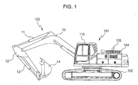
- FIG. 1 shows a side view illustrating an excavator of a related art.
- reference numeral 101 denotes an upper swing structure
- 102 denotes a working device
- 104 denotes an engine room
- 105 denotes an exhaust pipe for discharging exhaust gas from the engine
- 118 denotes a cabin.
- the working device 103 includes a boom 10, a boom cylinder 9, an arm 12, an arm cylinder 11, a bucket 14 and a bucket cylinder 13.
- the upper swing structure 101 can be swung on the lower driving structure 102 by a swing motor (not shown).
- the exhaust pipe 105 generally includes a bent distal end portion, through which gas is charged, so as to prevent rainwater from flowing therein.
- the overall height of the machine is configured to be within a transport limit dimension which is set forth in regulations.
- the front working device 103 has to be disassembled from the machine. Since the cabin 118 is difficult to be disassembled from the machine, the machine with the cabin mounted thereon is designed so as to meet the transport limit dimension.
- the exhaust pipe 105 the height of the exhaust pipe is higher than the cabin 118, the exhaust pipe has to be disassembled from the machine for the purpose of the transport. It is remarkably inconvenient and cumbersome.
- a rain hat 20 is provided as a rainwater ingression-preventing device, as shown in FIG. 2 .
- FIG. 2 is a view schematically illustrating a rain hat device for heavy construction equipment according to a related art, in which FIG. 2A is a partial cross-sectional view of a rain hat connected to a distal end portion of an exhaust pipe, and FIG. 2B is a side view of the rail hat connected to the exhaust pipe shown in FIG. 2A .
- the rain hat 20 includes a swing lever 22, a cap 23, a weight portion 24, a pivot support pin 25, a support bracket 26, an exhaust pipe fixing portion 27, and a fixing bolt 28.
- the support bracket 26 is placed at one side of the distal end portion 106 of the exhaust pipe 105, and then is fixed thereto by the fixing bolt 28.
- the swing lever is rotated around the pivot support pin 25 in a counterclockwise direction, as seen in the figure, together with the cap 23 and the weight portion 24.
- the cap 23 of the rain hat 20 comes in contact with the outlet portion of the distal end portion 106, and the cap 23 is seated on one side surface of the exhaust pipe 105.
- FIG. 3 is a view illustrating the operation of the rain hat device for heavy construction equipment according to the related art shown in FIG. 2 .
- Reference numeral 30 shows schematically a flow of the exhaust gas discharged at fast speed through the distal end portion 106 of the exhaust pipe 105 and the discharging port when the engine is driven.
- the cap 23 is upwardly pushed by dynamic spray force of the exhaust gas 30, and then is rotated in a counterclockwise direction, so that the distal end portion 106 of the exhaust pipe 105 and the exhaust gas discharging port 106a are opened.
- the exhaust gas 30 is discharged outwardly from the exhaust pipe 105, and simultaneously, the cap 23 is continuously maintained at a position higher than the distal end portion 106 of the exhaust pipe 105 and the discharging port by the dynamic pressure.
- the weight portion 24 and the swing lever 22 which are rotated together with the cap 23 serve as an operating unit of the rain hat 20.
- the dynamic force of the exhaust gas disappears, and thus the cap 23 and the operating unit are rotated in a clockwise direction by its own weight and are returned to the position in which the inner surface 21 comes in contact with the distal end portion 106 of the exhaust pipe 105 and the exhaust gas discharging port 106a, so that the cap and the operating unit are seated on the exhaust gas discharging port 106a.
- the cap 23 has a role of blocking inflow of the rainwater by closing the end face of the exhaust gas discharging port 106a.
- the dynamic discharging pressure of the exhaust gas overcomes the rotational moment of the operating unit and the cap 23 to push the cap 23 in the counterclockwise direction on the figure.
- the weight center G1 of the operating unit including the cap 23 is moved to the upward side of the pivot pin 25, and thus the weight center G1 is changed to the weight center G2 in a second section B.
- the pressure of the exhaust gas pushing the cap 23 upwardly disappears the cap 23 and the swing lever 22 are rotated in the clockwise direction, so that the weight center is changed to the initial position G1.
- the cap 23 is maintained in a floating state in the air by the pressure generated by the exhaust gas discharged at the high speed.
- the pressure of the exhaust gas is lower than the rotational moment M when the engine is idling or the engine stops, the inner surface 21 of the cap 23 contacts the distal end portion 106 of the exhaust pipe 105 to generate noise.
- US 3407720 A discloses an exhaust cover for an exhaust channel, which opens in response to exhaut gas pressure and which has a catch mechanism to prevent opening in response to physical forces external to the exhaustd channel, such as wind.
- An external covering cap and an internal catching cap are provided and a lip of the external covering cap rests on the upper opening of the exhaust channel when in a normally closed position.
- the present invention has been made to solve the above-mentioned problems occurring in the prior art while advantages achieved by the prior art are maintained intact.
- One subject to be solved by the present invention is to provide a rain hat device for heavy construction equipment, in which a weight center of a swing cover including a cover support portion and a weight is placed below a fixing shaft even though an engine stops or the engine is idling, so that the swing cover does not contact or collide against the distal end of an exhaust pipe and an exhaust gas discharging port, thereby preventing mechanical noise such as rattling noise from being generated repeatedly.
- a rain hat device for heavy construction equipment which is installed adjacent to an exhaust gas discharging port of a distal end portion of an exhaust pipe to prevent inflow of rainwater therein
- the rain hat device including a mounting bracket having a fixing shaft which is installed on an upper portion of the exhaust gas discharging port of the distal end portion of the exhaust pipe, the mounting bracket fixing the fixing shaft at a position higher than the distal end portion of the exhaust pipe; and a swing cover having a cover support portion connected to the fixing shaft and extending between the fixing shaft and the exhaust gas discharging port, and a weight portion, in which the cover support portion is rotated around the fixing shaft by pressure of exhaust gas discharged from the distal end portion, wherein the swing cover is installed on an upper portion of the exhaust gas discharging port in a floating state by the cover support portion so that a weight center is positioned between the fixing shaft and the exhaust gas discharging port when the discharging pressure of the exhaust gas is generated.
- the mounting bracket is provided at one side thereof with a clamp member for connecting the mounting bracket to the distal end portion of the exhaust pipe.
- the mounting bracket is fixed to one side of an engine room.
- the mounting bracket includes support columns supporting both distal ends of the fixing shaft.
- a rain hat device for heavy construction equipment which is installed adjacent to an exhaust gas discharging port of a distal end portion of an exhaust pipe to prevent inflow of rainwater therein
- the rain hat device including a mounting bracket having a fixing shaft which is installed on an upper portion of the exhaust gas discharging port of the distal end portion of the exhaust pipe, the mounting bracket fixing the fixing shaft at a position higher than the distal end portion of the exhaust pipe; and a swing cover having a cover support portion connected to the fixing shaft and extending between the fixing shaft and the exhaust gas discharging port, and a weight portion, in which the cover support portion is rotated around the fixing shaft by pressure of exhaust gas discharged from the distal end portion, wherein the mounting bracket includes support columns supporting both distal ends of the fixing shaft, and the swing cover is installed on an upper portion of the exhaust gas discharging port in a floating state by the cover support portions so that a weight center is positioned between the support columns when the exhaust gas is not discharged from the exhaust gas
- the swing cover is installed on the distal end portion of the exhaust pipe in a floating state, and the weight center of the swing cover is placed below the fixing shaft. Therefore, even though the engine stops or the engine is idling, the swing cover does not contact or collide against the distal end of an exhaust pipe and an exhaust gas discharging port, thereby preventing mechanical noise from being generated repeatedly.
- the height of the fixing shaft is set to be similar to that of the upper portion of the engine room, so that the whole height of the rain hat device can be maintained at a low level lower than the cabin. Therefore, it is possible to eliminate a problem in which work efforts remarkably increase, for example, cumbersome disassembling/assembling process is required for the transport thereof.
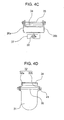
- FIGs. 4A to 4D are views illustrating a rain hat device for heavy construction equipment according to an embodiment of the present invention, in which FIG. 4A is a front view of the rain hat device for heavy construction equipment according to the present invention, FIG. 4B is a left side view of the rain hat device for heavy construction equipment shown in FIG. 4A , FIG. 4C is a right side view of the rain hat device for heavy construction equipment shown in FIG. 4A , and FIG. 4D is a plan view of the rain hat device for heavy construction equipment shown in FIG. 4A .
- FIG. 5 is a perspective view illustrating a variation of a weight center G in accordance with a swing operation state of the rain hat device for heavy construction equipment according to the present invention.
- FIG. 5 is a perspective view illustrating a variation of a weight center G in accordance with a swing operation state of the rain hat device for heavy construction equipment according to the present invention.
- FIG. 5 is a perspective view illustrating a variation of a weight center
- FIG. 6 is a perspective view illustrating a state in which the rain hat device is installed at a distal end portion of an exhaust pipe, according to an embodiment of the present invention.
- FIG. 7 is a perspective view illustrating a state in which the rain hat device is installed at an engine room, according to an embodiment of the present invention.
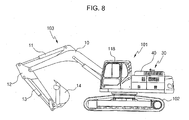
- FIG. 8 is a perspective view illustrating an excavator including the rain hat device for heavy construction equipment according to the present invention.
- reference numeral 31 denotes a swing cover
- 32 a cover support portion for fixing the swing cover
- 35 denotes a fixing shaft
- 36 denotes a mounting bracket
- G1 denotes a weight center of the swing cover at a normal state
- G2 denotes a weight center of the swing cover which is changed by discharging pressure of exhaust gas.
- the rain hat device for heavy construction equipment is installed adjacent to an exhaust gas discharging port 106a of a distal end portion 106 of an exhaust pipe to prevent inflow of rainwater therein.
- the rain hat device includes a mounting bracket 36 having a fixing shaft 35 which is installed on an upper portion of the exhaust gas discharging port 106a of the distal end portion 106 of the exhaust pipe, and fixing the fixing shaft 35 at a position higher than the distal end portion 106 of the exhaust pipe; and a swing cover 31 having a cover support portion 32 connected to the fixing shaft 35 and extending between the fixing shaft 35 and the exhaust gas discharging port 106a, and a weight portion 34, in which the cover support portion 32 is rotated around the fixing shaft 35 by pressure of exhaust gas discharged from the distal end portion 106.
- the swing cover 31 is installed on an upper portion of the exhaust gas discharging port 106a in a floating state by the cover support portion 32 so that a weight center G is positioned between the fixing shaft 35 and the exhaust gas discharging port 106a when the discharging pressure of the exhaust gas is generated.
- the weight portion 34 is welded to one surface of a longitudinal end portion of the swing cover 31 adjacent to the exhaust gas discharging port 106a. In a case where it is fixed by means of bolts, it is preferably configured in such a way that the weight center G of the swing cover 31 which is changed from a position G1 to a position G2 by the discharging pressure of the exhaust gas is positioned below the fixing shaft 35.
- the mounting bracket 36 is provided at one side thereof with a clamp member 37 for connecting the mounting bracket to the distal end portion 106 of the exhaust pipe.
- the clamp member 37 is closely supported on an outer circumference of the distal end portion 106 of the exhaust pipe, and is mounted on the outer circumference of the distal end portion 106 of the exhaust pipe by a bolting manner or a coupling manner.
- the mounting bracket 36 is fixed to one side of the engine room 40.
- the mounting bracket 36 has a function of setting the height of the fixing shaft 35 which is supported on an upper portion of the exhaust gas discharging port 106a of the distal end portion 106 of the exhaust pipe.
- the mounting bracket 36 includes support columns 36a and 36b connected to both distal ends of the fixing shaft 35, and cover support portions 32a and 32b are rotatably fixed to the fixing shaft 35 between the support columns 36a and 36b.
- the rain hat device for heavy construction equipment which is installed adjacent to an exhaust gas discharging port 106a of a distal end portion 106 of an exhaust pipe to prevent inflow of rainwater therein, includes a mounting bracket 36 having a fixing shaft 35 which is installed on an upper portion of the exhaust gas discharging port 106a of the distal end portion 106 of the exhaust pipe, and fixing the fixing shaft 35 at a position higher than the distal end portion 106 of the exhaust pipe; and a swing cover 31 having a cover support portion 32 connected to the fixing shaft 35 and extending between the fixing shaft 35 and the exhaust gas discharging port 106a, and a weight portion 34, in which the cover support portion 32 is rotated around the fixing shaft 35 by discharging pressure of exhaust gas discharged from the distal end portion 106, wherein the mounting bracket 36 includes support columns 36a and 36b for supporting both distal ends of the fixing shaft 35, and the swing cover 31 is installed on an upper portion of the exhaust gas discharging port 106a in a floating state
- the swing cover 31 is supported by the cover support portions 32a and 32b so that the weight center G is positioned between the support columns 36a and 36b and below the fixing shaft 35 when the exhaust gas is not discharged from the exhaust gas discharging port 106a.
- the fixing shaft 35 is provided at both sides thereof with provided a release prevention pin 41 for preventing release of a shaft coupling unit including the cover support portions 32a and 32b, the mounting bracket 36 and the support columns 36a and 36b when the swing cover 31 swings.
- the clamp member 37 formed on one side of the mounting bracket 36 is connected to an outer circumference of the distal end portion 106 of the exhaust pipe adjacent to the exhaust gas discharging port 106a.
- the fixing shaft 35 is installed on the support columns 36a and 36b of the mounting bracket 36, and the upper portion of the cover support portion 32 is connected to the fixing shaft 35, so that the swing cover 31 including the weight 34 is suspended from the fixing shaft 35.
- the lower portion of the swing cover 31 is fixed to the upper portion of the exhaust gas discharging port 106a by the clamping member 37, and is maintained in a floating state which is spaced apart from the upper portion, thereby preventing rainwater or dust from flowing in the exhaust gas discharging port 106a by the swing cover 31.
- the weight center G of the rotating unit including the swing cover 31, the cover support portion 32 and the weight 34 acts vertically with respect to a gravity direction, and thus is set just below the fixing shaft 35 so that the lower portion or a bottom surface of the swing cover 31 is placed in substantially horizontal direction.
- the weight center G is set just below the fixing shaft 35.
- the swing cover 31 is placed in a floating state at a desired height from the exhaust gas discharging port 106a.
- the weight center G of the swing cover 31 suspended from the fixing shaft 35 is placed at a position closer to the position G1 which is placed below the fixing shaft 35, even though it shakes slightly by slight discharging pressure of the exhaust gas.
- the weight center is changed by a dynamic inertial force of the swing cover 31 which is generated by the rotational moment M due to its own weight of the swing cover 31. Even though the inertial force is slightly varied, the weight center G of the swing cover 31 is set below the fixing shaft 35 or between the support columns 36a and 36b of the mounting bracket 36 as a normal position.
- the weight center G of the swing cover 32 is moved to a point B in a counterclockwise direction around the fixing shaft 35, so that the weight center is changed to the position G2.
- the swing cover 31 supported by the cover support portion 32 may intermittently stand erect. However, since the weight portion 34 serves as most of load W below the fixing shaft 35, the weight center G2 of the swing cover 31 is placed under the fixing shaft 35.
- the pressure of the exhaust gas discharged from the exhaust gas discharging port 106a is lowered than the rotational moment M due to its own weight of the swing cover 31, and the swing cover 31 serving as the operating unit is rotated in the clockwise direction around the fixing shaft 35, and is moved in a horizontal direction from the exhaust gas discharging port 106a.
- the weight center G of the operating unit is set just below the fixing shaft 35, and the swing cover 31 is maintained in a horizontal state without contacting or colliding against the distal end 106 of the exhaust pipe and the exhaust gas discharging port 106a.
- the swing cover 31 does not contact or collide against the distal end 106 of the exhaust pipe and the exhaust gas discharging port 106a, so that mechanical noise such as rattling noise is not generated repeatedly.
- the lower portion of the mounting bracket 36 may be fixed to one side of the upper portion of the engine room 40.
- the swing cover 31 is configured so that it is maintained in a floating state in the air at a position spaced apart from the distal end 106 of the exhaust pipe and the exhaust gas discharging port 106a, similar to the above embodiment.
- the swing cover 31 can be moved in the counterclockwise direction or clockwise direction around the fixing shaft 35 by the pressure of the exhaust gas discharged from the exhaust gas discharging port 106a. If the engine stops or the exhaust gas is not discharged, the weight center G is set usually below the fixing shaft 35 by the rotational moment M of the operating unit including the swing cover 31, the cover support portion 32 and the weight 34, similar to the above operating principle.
- the height of the fixing shaft 35 and the clamp member 37 supported by the mounting bracket is set to be similar to that of the upper portion of the engine room, so that the whole height of the rain hat device can be maintained at a low level lower than the cabin. Therefore, it is possible to eliminate a drawback contained in the related art in which work efforts remarkably increase, for example, cumbersome disassembling/assembling process is required for the transport thereof.
Landscapes
- Engineering & Computer Science (AREA)
- General Engineering & Computer Science (AREA)
- Mechanical Engineering (AREA)
- Chemical & Material Sciences (AREA)
- Combustion & Propulsion (AREA)
- Mining & Mineral Resources (AREA)
- Civil Engineering (AREA)
- Structural Engineering (AREA)
- Exhaust Silencers (AREA)
- Component Parts Of Construction Machinery (AREA)
- Cooling, Air Intake And Gas Exhaust, And Fuel Tank Arrangements In Propulsion Units (AREA)
Claims (4)
- Dispositif de chapeau de pluie pour équipement de construction lourd, qui est installé adjacent à un orifice de décharge de gaz d'échappement (106a) d'une partie d'extrémité distale (106) d'un tuyau d'échappement pour éviter un flux d'entrée d'eau de pluie dans ce dernier, le dispositif de chapeau de pluie comprenant:un support de montage (36) présentant un arbre de fixation (35) qui est installé sur une partie supérieure de l'orifice de décharge de gaz d'échappement (106a) de la partie d'extrémité distale (106) du tuyau d'échappement, le support de montage (36) fixant l'arbre de fixation (35) en une position plus haute que la partie d'extrémité distale (106) du tuyau d'échappement;dans lequel le support de montage (36) est fixé à un côté d'une chambre de moteur (40); etun couvercle oscillant (31) présentant une partie de soutien de couvercle (32) connectée à l'arbre de fixation (35) et s'étendant entre l'arbre de fixation (35) et l'orifice de décharge de gaz d'échappement (106a), et une partie de poids (34) dans laquelle la partie de soutien de couvercle (32) est entraînée en rotation autour de l'arbre de fixation (35) par la pression du gaz d'échappement déchargé de la partie d'extrémité distale (106);caractérisé par le fait quele couvercle oscillant (31) est installé sur une partie supérieure de l'orifice de décharge de gaz d'échappement (106a) dans un état flottant par la partie de soutien de couvercle (32) de sorte que le couvercle oscillant (31) soit espacé de la partie d'extrémité distale (106) du tuyau d'échappement lorsque le gaz d'échappement n'est pas déchargé de l'orifice de décharge de gaz d'échappement (106a), et de sorte que- un centre de poids soit positionné entre l'arbre de fixation (35) et l'orifice de décharge de gaz d'échappement (106a) lorsque la pression de décharge du gaz d'échappement est générée, ou- un centre de poids soit positionné entre les colonnes de soutien (36a, 36b) soutenant les deux extrémités distales de l'arbre de fixation (35) lorsque le gaz d'échappement n'est pas déchargé de l'orifice de décharge de gaz d'échappement (106a).
- Dispositif de chapeau de pluie selon la revendication 1, dans lequel le support de montage (36) est prévu d'un côté de ce dernier avec un élément de serrage (37) pour connecter le support de montage (37) à la partie d'extrémité distale (106) du tuyau d'échappement.
- Dispositif de chapeau de pluie selon la revendication 1, dans lequel le support de montage (36) comporte des colonnes de soutien (36a, 36b) soutenant les deux extrémités distales de l'arbre de fixation (35).
- Dispositif de chapeau de pluie selon l'une des revendications 1 à 3, dans lequel le centre de poids est placé juste au-dessous de l'arbre de fixation (35) lorsque le gaz d'échappement n'est pas déchargé de l'orifice de décharge de gaz d'échappement (106a).
Applications Claiming Priority (1)
| Application Number | Priority Date | Filing Date | Title |
|---|---|---|---|
| KR1020090011047A KR20100091719A (ko) | 2009-02-11 | 2009-02-11 | 건설중장비용 레인 햇 장치 |
Publications (2)
| Publication Number | Publication Date |
|---|---|
| EP2218885A1 EP2218885A1 (fr) | 2010-08-18 |
| EP2218885B1 true EP2218885B1 (fr) | 2015-03-25 |
Family
ID=42153922
Family Applications (1)
| Application Number | Title | Priority Date | Filing Date |
|---|---|---|---|
| EP10152904.8A Active EP2218885B1 (fr) | 2009-02-11 | 2010-02-08 | Dispositif de chapeau de pluie pour équipement lourd de construction |
Country Status (5)
| Country | Link |
|---|---|
| US (1) | US20100200792A1 (fr) |
| EP (1) | EP2218885B1 (fr) |
| JP (1) | JP5564280B2 (fr) |
| KR (1) | KR20100091719A (fr) |
| CN (1) | CN101798828A (fr) |
Families Citing this family (8)
| Publication number | Priority date | Publication date | Assignee | Title |
|---|---|---|---|---|
| CN102810931A (zh) * | 2012-07-20 | 2012-12-05 | 昆山西马克动力机械有限公司 | 防雨帽 |
| CN103670644B (zh) * | 2013-12-06 | 2016-02-03 | 中联重科股份有限公司 | 排气管防护装置及具有其的工程机械 |
| CN104727917B (zh) * | 2015-03-04 | 2017-07-25 | 芜湖造船厂有限公司 | 一种船舶用发动机排气管防雨水装置 |
| JP6883853B2 (ja) * | 2017-06-26 | 2021-06-09 | 範多機械株式会社 | 換気システム及びそれを用いた道路舗装車両 |
| CN109458248B (zh) * | 2017-09-06 | 2020-03-24 | 宝沃汽车(中国)有限公司 | 车辆的排气系统、车辆及排气方法 |
| US12345172B2 (en) | 2020-12-02 | 2025-07-01 | Yantai Jereh Petroleum Equipment & Technologies Co., Ltd. | Fracturing device, engine and exhaust apparatus thereof |
| US11105250B1 (en) | 2020-12-02 | 2021-08-31 | Yantai Jereh Petroleum Equipment & Technologies Co., Ltd. | Rain shield assembly, pipe assembly and turbine fracturing unit |
| CN115370456B (zh) * | 2022-09-29 | 2023-05-16 | 芜湖盈德智能科技有限公司 | 一种柴油机尾气后处理器 |
Family Cites Families (23)
| Publication number | Priority date | Publication date | Assignee | Title |
|---|---|---|---|---|
| FR878084A (fr) * | 1941-08-14 | 1943-01-11 | Chapiteau aspirateur pour conduite de fumée et de ventilation | |
| US2694358A (en) * | 1950-08-01 | 1954-11-16 | Anthes Force Oiler Company | Exhaust pipe cover |
| US3407720A (en) | 1967-01-03 | 1968-10-29 | Albert M. Westerman | Exhaust cover |
| US3523499A (en) * | 1968-10-18 | 1970-08-11 | Eberspaecher J | Weather cap construction |
| US3667260A (en) * | 1971-01-25 | 1972-06-06 | Master Lock Co | Exhaust pipe protector lock |
| JPS5042914Y2 (fr) * | 1971-06-30 | 1975-12-08 | ||
| US3791282A (en) * | 1972-11-10 | 1974-02-12 | Deere & Co | Weather cap for exhaust pipe |
| JPS5282610U (fr) * | 1975-12-19 | 1977-06-20 | ||
| US4205706A (en) * | 1978-07-12 | 1980-06-03 | Nelson Industries, Inc. | Protective cap for an exhaust pipe |
| US4255928A (en) * | 1978-12-11 | 1981-03-17 | Mercury Metal Products | Swingable rain cover for vertical exhaust pipes with stop means |
| US4226173A (en) * | 1979-05-07 | 1980-10-07 | Nelson Industries, Inc. | Protective cap for an exhaust pipe |
| US4380952A (en) * | 1981-01-28 | 1983-04-26 | Mercury Metal Products | Cover assembly for vertical exhaust pipes |
| US4383478A (en) * | 1981-07-29 | 1983-05-17 | Mercury Metal Products, Inc. | Rain cap with pivot support means |
| US4495859A (en) * | 1983-07-25 | 1985-01-29 | Mercury Metal Products, Inc. | Cover assembly for vertical exhaust pipes |
| US4580488A (en) * | 1985-02-19 | 1986-04-08 | Olibin Limited | Weather caps for exhaust pipes |
| US4671171A (en) * | 1985-12-31 | 1987-06-09 | Robert Brill | Aerodynamically operated rain cap |
| US4742766A (en) * | 1986-05-12 | 1988-05-10 | Davison Jerome G | Dynamically balanced exhaust pipe cap |
| US4667582A (en) * | 1986-05-12 | 1987-05-26 | Davison Jerome G | Dynamically balanced exhaust pipe cap |
| US4727796A (en) * | 1986-10-28 | 1988-03-01 | Derkach W George | Weather cap for upstanding exhaust pipes |
| US4821629A (en) * | 1988-05-04 | 1989-04-18 | Davison Jerom G | Dynamically balanced exhaust pipe cap |
| US5092226A (en) * | 1990-12-12 | 1992-03-03 | Eratech Inc. | Incinerator chimney stack valve mechanism |
| US6921327B2 (en) * | 2003-09-29 | 2005-07-26 | Richard Urash | Exhaust pipe cover |
| KR20080006706A (ko) * | 2006-07-13 | 2008-01-17 | 볼보 컨스트럭션 이키프먼트 홀딩 스웨덴 에이비 | 건설중장비의 레인햇 |
-
2009
- 2009-02-11 KR KR1020090011047A patent/KR20100091719A/ko not_active Ceased
-
2010
- 2010-02-08 EP EP10152904.8A patent/EP2218885B1/fr active Active
- 2010-02-08 CN CN201019185022A patent/CN101798828A/zh active Pending
- 2010-02-09 US US12/702,712 patent/US20100200792A1/en not_active Abandoned
- 2010-02-10 JP JP2010027177A patent/JP5564280B2/ja active Active
Also Published As
| Publication number | Publication date |
|---|---|
| US20100200792A1 (en) | 2010-08-12 |
| JP5564280B2 (ja) | 2014-07-30 |
| KR20100091719A (ko) | 2010-08-19 |
| JP2010184701A (ja) | 2010-08-26 |
| EP2218885A1 (fr) | 2010-08-18 |
| CN101798828A (zh) | 2010-08-11 |
Similar Documents
| Publication | Publication Date | Title |
|---|---|---|
| EP2218885B1 (fr) | Dispositif de chapeau de pluie pour équipement lourd de construction | |
| EP2130979A2 (fr) | Appareil de marchepied pour équipement de construction lourde et abatteuse-ébrancheuse disposant d'un système de nivellement | |
| JP3962049B2 (ja) | 自動開閉装置 | |
| US8720628B2 (en) | Working machine with equipment room | |
| JP2007100351A (ja) | 作業機械 | |
| JP5053212B2 (ja) | ローダ作業機のエンジン設置構造 | |
| JP3745510B2 (ja) | 建設機械 | |
| JP3461079B2 (ja) | 全旋回式作業機 | |
| JP4180994B2 (ja) | 建設機械 | |
| JP2008267156A (ja) | 建設機械の排気管構造 | |
| JP5405421B2 (ja) | 建設機械 | |
| KR20080006706A (ko) | 건설중장비의 레인햇 | |
| JP2008128077A (ja) | 作業機械の冷却装置の清掃用構造 | |
| JP2008303714A (ja) | 掘削作業車 | |
| JP6437803B2 (ja) | 建設機械 | |
| KR200442937Y1 (ko) | 호이스트용 체인박스 및 이를 구비한 체인 호이스트 | |
| JP4096600B2 (ja) | マニホールドの接合構造 | |
| JP2005002572A (ja) | 掘削作業車 | |
| JP2007217922A (ja) | 建設機械 | |
| KR200239703Y1 (ko) | 배기관의 출구 커버구조 | |
| JP4614894B2 (ja) | 作業車のキャノピ | |
| JP3626392B2 (ja) | バックホーの旋回台 | |
| JP4738188B2 (ja) | 作業車のキャノピ | |
| JPH06212665A (ja) | 旋回作業車 | |
| CN210798603U (zh) | 快拆式门结构及箱式电站 |
Legal Events
| Date | Code | Title | Description |
|---|---|---|---|
| PUAI | Public reference made under article 153(3) epc to a published international application that has entered the european phase |
Free format text: ORIGINAL CODE: 0009012 |
|
| AK | Designated contracting states |
Kind code of ref document: A1 Designated state(s): AT BE BG CH CY CZ DE DK EE ES FI FR GB GR HR HU IE IS IT LI LT LU LV MC MK MT NL NO PL PT RO SE SI SK SM TR |
|
| AX | Request for extension of the european patent |
Extension state: AL BA RS |
|
| RIN1 | Information on inventor provided before grant (corrected) |
Inventor name: IKEDA, TOSHIMICHI Inventor name: CHO, GYEN SOO Inventor name: JEONG, KYO CHEON |
|
| 17P | Request for examination filed |
Effective date: 20110218 |
|
| GRAP | Despatch of communication of intention to grant a patent |
Free format text: ORIGINAL CODE: EPIDOSNIGR1 |
|
| RIC1 | Information provided on ipc code assigned before grant |
Ipc: F23J 13/08 20060101ALI20140923BHEP Ipc: F01N 13/08 20100101AFI20140923BHEP |
|
| INTG | Intention to grant announced |
Effective date: 20141008 |
|
| GRAS | Grant fee paid |
Free format text: ORIGINAL CODE: EPIDOSNIGR3 |
|
| GRAA | (expected) grant |
Free format text: ORIGINAL CODE: 0009210 |
|
| AK | Designated contracting states |
Kind code of ref document: B1 Designated state(s): AT BE BG CH CY CZ DE DK EE ES FI FR GB GR HR HU IE IS IT LI LT LU LV MC MK MT NL NO PL PT RO SE SI SK SM TR |
|
| REG | Reference to a national code |
Ref country code: GB Ref legal event code: FG4D |
|
| REG | Reference to a national code |
Ref country code: CH Ref legal event code: EP |
|
| REG | Reference to a national code |
Ref country code: IE Ref legal event code: FG4D |
|
| REG | Reference to a national code |
Ref country code: DE Ref legal event code: R096 Ref document number: 602010023323 Country of ref document: DE Effective date: 20150507 |
|
| REG | Reference to a national code |
Ref country code: AT Ref legal event code: REF Ref document number: 718023 Country of ref document: AT Kind code of ref document: T Effective date: 20150515 |
|
| PG25 | Lapsed in a contracting state [announced via postgrant information from national office to epo] |
Ref country code: NO Free format text: LAPSE BECAUSE OF FAILURE TO SUBMIT A TRANSLATION OF THE DESCRIPTION OR TO PAY THE FEE WITHIN THE PRESCRIBED TIME-LIMIT Effective date: 20150625 Ref country code: FI Free format text: LAPSE BECAUSE OF FAILURE TO SUBMIT A TRANSLATION OF THE DESCRIPTION OR TO PAY THE FEE WITHIN THE PRESCRIBED TIME-LIMIT Effective date: 20150325 Ref country code: LT Free format text: LAPSE BECAUSE OF FAILURE TO SUBMIT A TRANSLATION OF THE DESCRIPTION OR TO PAY THE FEE WITHIN THE PRESCRIBED TIME-LIMIT Effective date: 20150325 Ref country code: SE Free format text: LAPSE BECAUSE OF FAILURE TO SUBMIT A TRANSLATION OF THE DESCRIPTION OR TO PAY THE FEE WITHIN THE PRESCRIBED TIME-LIMIT Effective date: 20150325 Ref country code: HR Free format text: LAPSE BECAUSE OF FAILURE TO SUBMIT A TRANSLATION OF THE DESCRIPTION OR TO PAY THE FEE WITHIN THE PRESCRIBED TIME-LIMIT Effective date: 20150325 |
|
| REG | Reference to a national code |
Ref country code: AT Ref legal event code: MK05 Ref document number: 718023 Country of ref document: AT Kind code of ref document: T Effective date: 20150325 |
|
| REG | Reference to a national code |
Ref country code: LT Ref legal event code: MG4D |
|
| PG25 | Lapsed in a contracting state [announced via postgrant information from national office to epo] |
Ref country code: GR Free format text: LAPSE BECAUSE OF FAILURE TO SUBMIT A TRANSLATION OF THE DESCRIPTION OR TO PAY THE FEE WITHIN THE PRESCRIBED TIME-LIMIT Effective date: 20150626 Ref country code: LV Free format text: LAPSE BECAUSE OF FAILURE TO SUBMIT A TRANSLATION OF THE DESCRIPTION OR TO PAY THE FEE WITHIN THE PRESCRIBED TIME-LIMIT Effective date: 20150325 |
|
| PG25 | Lapsed in a contracting state [announced via postgrant information from national office to epo] |
Ref country code: NL Free format text: LAPSE BECAUSE OF FAILURE TO SUBMIT A TRANSLATION OF THE DESCRIPTION OR TO PAY THE FEE WITHIN THE PRESCRIBED TIME-LIMIT Effective date: 20150325 |
|
| PG25 | Lapsed in a contracting state [announced via postgrant information from national office to epo] |
Ref country code: CZ Free format text: LAPSE BECAUSE OF FAILURE TO SUBMIT A TRANSLATION OF THE DESCRIPTION OR TO PAY THE FEE WITHIN THE PRESCRIBED TIME-LIMIT Effective date: 20150325 Ref country code: EE Free format text: LAPSE BECAUSE OF FAILURE TO SUBMIT A TRANSLATION OF THE DESCRIPTION OR TO PAY THE FEE WITHIN THE PRESCRIBED TIME-LIMIT Effective date: 20150325 Ref country code: PT Free format text: LAPSE BECAUSE OF FAILURE TO SUBMIT A TRANSLATION OF THE DESCRIPTION OR TO PAY THE FEE WITHIN THE PRESCRIBED TIME-LIMIT Effective date: 20150727 Ref country code: SK Free format text: LAPSE BECAUSE OF FAILURE TO SUBMIT A TRANSLATION OF THE DESCRIPTION OR TO PAY THE FEE WITHIN THE PRESCRIBED TIME-LIMIT Effective date: 20150325 Ref country code: RO Free format text: LAPSE BECAUSE OF FAILURE TO SUBMIT A TRANSLATION OF THE DESCRIPTION OR TO PAY THE FEE WITHIN THE PRESCRIBED TIME-LIMIT Effective date: 20150325 Ref country code: ES Free format text: LAPSE BECAUSE OF FAILURE TO SUBMIT A TRANSLATION OF THE DESCRIPTION OR TO PAY THE FEE WITHIN THE PRESCRIBED TIME-LIMIT Effective date: 20150325 |
|
| PG25 | Lapsed in a contracting state [announced via postgrant information from national office to epo] |
Ref country code: PL Free format text: LAPSE BECAUSE OF FAILURE TO SUBMIT A TRANSLATION OF THE DESCRIPTION OR TO PAY THE FEE WITHIN THE PRESCRIBED TIME-LIMIT Effective date: 20150325 Ref country code: AT Free format text: LAPSE BECAUSE OF FAILURE TO SUBMIT A TRANSLATION OF THE DESCRIPTION OR TO PAY THE FEE WITHIN THE PRESCRIBED TIME-LIMIT Effective date: 20150325 Ref country code: IS Free format text: LAPSE BECAUSE OF FAILURE TO SUBMIT A TRANSLATION OF THE DESCRIPTION OR TO PAY THE FEE WITHIN THE PRESCRIBED TIME-LIMIT Effective date: 20150725 |
|
| REG | Reference to a national code |
Ref country code: FR Ref legal event code: PLFP Year of fee payment: 7 |
|
| REG | Reference to a national code |
Ref country code: DE Ref legal event code: R097 Ref document number: 602010023323 Country of ref document: DE |
|
| PG25 | Lapsed in a contracting state [announced via postgrant information from national office to epo] |
Ref country code: DK Free format text: LAPSE BECAUSE OF FAILURE TO SUBMIT A TRANSLATION OF THE DESCRIPTION OR TO PAY THE FEE WITHIN THE PRESCRIBED TIME-LIMIT Effective date: 20150325 |
|
| PLBE | No opposition filed within time limit |
Free format text: ORIGINAL CODE: 0009261 |
|
| STAA | Information on the status of an ep patent application or granted ep patent |
Free format text: STATUS: NO OPPOSITION FILED WITHIN TIME LIMIT |
|
| 26N | No opposition filed |
Effective date: 20160105 |
|
| PG25 | Lapsed in a contracting state [announced via postgrant information from national office to epo] |
Ref country code: BE Free format text: LAPSE BECAUSE OF NON-PAYMENT OF DUE FEES Effective date: 20160229 Ref country code: SI Free format text: LAPSE BECAUSE OF FAILURE TO SUBMIT A TRANSLATION OF THE DESCRIPTION OR TO PAY THE FEE WITHIN THE PRESCRIBED TIME-LIMIT Effective date: 20150325 |
|
| PG25 | Lapsed in a contracting state [announced via postgrant information from national office to epo] |
Ref country code: BE Free format text: LAPSE BECAUSE OF FAILURE TO SUBMIT A TRANSLATION OF THE DESCRIPTION OR TO PAY THE FEE WITHIN THE PRESCRIBED TIME-LIMIT Effective date: 20150325 |
|
| PG25 | Lapsed in a contracting state [announced via postgrant information from national office to epo] |
Ref country code: MC Free format text: LAPSE BECAUSE OF FAILURE TO SUBMIT A TRANSLATION OF THE DESCRIPTION OR TO PAY THE FEE WITHIN THE PRESCRIBED TIME-LIMIT Effective date: 20150325 Ref country code: LU Free format text: LAPSE BECAUSE OF FAILURE TO SUBMIT A TRANSLATION OF THE DESCRIPTION OR TO PAY THE FEE WITHIN THE PRESCRIBED TIME-LIMIT Effective date: 20160208 |
|
| REG | Reference to a national code |
Ref country code: CH Ref legal event code: PL |
|
| PG25 | Lapsed in a contracting state [announced via postgrant information from national office to epo] |
Ref country code: CH Free format text: LAPSE BECAUSE OF NON-PAYMENT OF DUE FEES Effective date: 20160229 Ref country code: LI Free format text: LAPSE BECAUSE OF NON-PAYMENT OF DUE FEES Effective date: 20160229 |
|
| REG | Reference to a national code |
Ref country code: IE Ref legal event code: MM4A |
|
| PG25 | Lapsed in a contracting state [announced via postgrant information from national office to epo] |
Ref country code: IE Free format text: LAPSE BECAUSE OF NON-PAYMENT OF DUE FEES Effective date: 20160208 |
|
| REG | Reference to a national code |
Ref country code: FR Ref legal event code: PLFP Year of fee payment: 8 |
|
| PG25 | Lapsed in a contracting state [announced via postgrant information from national office to epo] |
Ref country code: MT Free format text: LAPSE BECAUSE OF FAILURE TO SUBMIT A TRANSLATION OF THE DESCRIPTION OR TO PAY THE FEE WITHIN THE PRESCRIBED TIME-LIMIT Effective date: 20150325 |
|
| REG | Reference to a national code |
Ref country code: FR Ref legal event code: PLFP Year of fee payment: 9 |
|
| PG25 | Lapsed in a contracting state [announced via postgrant information from national office to epo] |
Ref country code: SM Free format text: LAPSE BECAUSE OF FAILURE TO SUBMIT A TRANSLATION OF THE DESCRIPTION OR TO PAY THE FEE WITHIN THE PRESCRIBED TIME-LIMIT Effective date: 20150325 Ref country code: CY Free format text: LAPSE BECAUSE OF FAILURE TO SUBMIT A TRANSLATION OF THE DESCRIPTION OR TO PAY THE FEE WITHIN THE PRESCRIBED TIME-LIMIT Effective date: 20150325 Ref country code: HU Free format text: LAPSE BECAUSE OF FAILURE TO SUBMIT A TRANSLATION OF THE DESCRIPTION OR TO PAY THE FEE WITHIN THE PRESCRIBED TIME-LIMIT; INVALID AB INITIO Effective date: 20100208 |
|
| PG25 | Lapsed in a contracting state [announced via postgrant information from national office to epo] |
Ref country code: MK Free format text: LAPSE BECAUSE OF FAILURE TO SUBMIT A TRANSLATION OF THE DESCRIPTION OR TO PAY THE FEE WITHIN THE PRESCRIBED TIME-LIMIT Effective date: 20150325 Ref country code: MT Free format text: LAPSE BECAUSE OF FAILURE TO SUBMIT A TRANSLATION OF THE DESCRIPTION OR TO PAY THE FEE WITHIN THE PRESCRIBED TIME-LIMIT Effective date: 20160229 Ref country code: TR Free format text: LAPSE BECAUSE OF FAILURE TO SUBMIT A TRANSLATION OF THE DESCRIPTION OR TO PAY THE FEE WITHIN THE PRESCRIBED TIME-LIMIT Effective date: 20150325 |
|
| PG25 | Lapsed in a contracting state [announced via postgrant information from national office to epo] |
Ref country code: BG Free format text: LAPSE BECAUSE OF FAILURE TO SUBMIT A TRANSLATION OF THE DESCRIPTION OR TO PAY THE FEE WITHIN THE PRESCRIBED TIME-LIMIT Effective date: 20150325 |
|
| REG | Reference to a national code |
Ref country code: DE Ref legal event code: R081 Ref document number: 602010023323 Country of ref document: DE Owner name: VOLVO CONSTRUCTION EQUIPMENT AB, SE Free format text: FORMER OWNER: VOLVO CONSTRUCTION EQUIPMENT HOLDING SWEDEN AB, ESKILSTUNA, SE |
|
| REG | Reference to a national code |
Ref country code: DE Ref legal event code: R082 Ref document number: 602010023323 Country of ref document: DE Representative=s name: SCHOPPE, ZIMMERMANN, STOECKELER, ZINKLER, SCHE, DE |
|
| PGFP | Annual fee paid to national office [announced via postgrant information from national office to epo] |
Ref country code: FR Payment date: 20240226 Year of fee payment: 15 |
|
| PGFP | Annual fee paid to national office [announced via postgrant information from national office to epo] |
Ref country code: DE Payment date: 20250226 Year of fee payment: 16 |
|
| PGFP | Annual fee paid to national office [announced via postgrant information from national office to epo] |
Ref country code: IT Payment date: 20250225 Year of fee payment: 16 Ref country code: GB Payment date: 20250218 Year of fee payment: 16 |
|
| PG25 | Lapsed in a contracting state [announced via postgrant information from national office to epo] |
Ref country code: FR Free format text: LAPSE BECAUSE OF NON-PAYMENT OF DUE FEES Effective date: 20250228 |