EP2218940B1 - Machines électriques rotatives - Google Patents
Machines électriques rotatives Download PDFInfo
- Publication number
- EP2218940B1 EP2218940B1 EP10001154.3A EP10001154A EP2218940B1 EP 2218940 B1 EP2218940 B1 EP 2218940B1 EP 10001154 A EP10001154 A EP 10001154A EP 2218940 B1 EP2218940 B1 EP 2218940B1
- Authority
- EP
- European Patent Office
- Prior art keywords
- rotatable shaft
- electrical machine
- rotating electrical
- torsional vibration
- damper
- Prior art date
- Legal status (The legal status is an assumption and is not a legal conclusion. Google has not performed a legal analysis and makes no representation as to the accuracy of the status listed.)
- Not-in-force
Links
Images


Classifications
-
- H—ELECTRICITY
- H02—GENERATION; CONVERSION OR DISTRIBUTION OF ELECTRIC POWER
- H02K—DYNAMO-ELECTRIC MACHINES
- H02K7/00—Arrangements for handling mechanical energy structurally associated with dynamo-electric machines, e.g. structural association with mechanical driving motors or auxiliary dynamo-electric machines
- H02K7/003—Couplings; Details of shafts
-
- F—MECHANICAL ENGINEERING; LIGHTING; HEATING; WEAPONS; BLASTING
- F16—ENGINEERING ELEMENTS AND UNITS; GENERAL MEASURES FOR PRODUCING AND MAINTAINING EFFECTIVE FUNCTIONING OF MACHINES OR INSTALLATIONS; THERMAL INSULATION IN GENERAL
- F16F—SPRINGS; SHOCK-ABSORBERS; MEANS FOR DAMPING VIBRATION
- F16F15/00—Suppression of vibrations in systems; Means or arrangements for avoiding or reducing out-of-balance forces, e.g. due to motion
- F16F15/10—Suppression of vibrations in rotating systems by making use of members moving with the system
- F16F15/16—Suppression of vibrations in rotating systems by making use of members moving with the system using a fluid or pasty material
-
- Y—GENERAL TAGGING OF NEW TECHNOLOGICAL DEVELOPMENTS; GENERAL TAGGING OF CROSS-SECTIONAL TECHNOLOGIES SPANNING OVER SEVERAL SECTIONS OF THE IPC; TECHNICAL SUBJECTS COVERED BY FORMER USPC CROSS-REFERENCE ART COLLECTIONS [XRACs] AND DIGESTS
- Y10—TECHNICAL SUBJECTS COVERED BY FORMER USPC
- Y10T—TECHNICAL SUBJECTS COVERED BY FORMER US CLASSIFICATION
- Y10T29/00—Metal working
- Y10T29/49—Method of mechanical manufacture
- Y10T29/49002—Electrical device making
- Y10T29/49009—Dynamoelectric machine
Definitions
- the invention relates to rotating electrical machines such as motors and generators.
- Torsional vibration dampers are commonly used to provide mechanical damping in physically large generator sets where a torque is applied to the rotatable shaft of an electrical machine by an external device (prime mover) such as a diesel engine or turbine, for example. Such TVDs are used to prevent the build up of dangerous torsional vibration levels in the rotatable shaft of the electrical machine during start-up, shut-down and the normal operation of the generator set.
- An electrical machine and a torsional vibration damper is disclosed in DE 199 43 038 A1 .
- a stand-alone TVD includes a primary member that is driven by an output shaft of the prime mover and a secondary member that applies a torque to the rotatable shaft of the electrical machine.
- the primary and secondary members are elastically connected together by suitable spring sets so that the torque that is applied to the primary member by the output shaft of the prime mover is transferred through the spring sets to the secondary member.
- Buffers are often provided within the TVD to restrict the relative rotational movement between the primary and secondary members and hence prevent overloading and excessive deflection of the spring sets.
- Such conventional stand-alone TVDs are physically large, expensive to manufacture and install and add significantly to the overall length of the generator set. They can also suffer from misalignment problems.
- damping chambers formed in the body of the secondary member are filled with a viscous working fluid, typically engine oil that is circulated from the prime mover.
- a viscous working fluid typically engine oil that is circulated from the prime mover.
- the damping chambers are connected together by narrow passageways. Relative rotational movement between the primary and secondary members of the TVD forces the viscous working fluid through the passageways between the damping chambers and past the ends of the spring sets (e.g. leaf springs) to dampen torsional vibrations.
- the engine oil has a high operating temperature (about 80°C) and often contains contaminant particles that can cause blockages, increase wear and reduce the reliability of the TVD.
- the present invention improves on the known use of conventional stand-alone torsional vibration dampers (TVDs) by effectively integrating a TVD that provides mechanical damping within a rotating electrical machine. This results in a generator set or motor set that is significantly more physically compact and hence cheaper and easier to install.
- TVDs stand-alone torsional vibration dampers
- Other technical advantages arising from the integration of the TVD within the rotating electrical machine e.g. performance optimisation arising from improved control of the mechanical damping provided by the TVD are also discussed in more detail below.
- the present invention provides a rotating electrical machine (e.g. a motor or generator) comprising: a rotatable shaft, a rotor assembly (e.g. a rotor core pack) concentric with the rotatable shaft and having a first end and a second end, a rotatable shaft, and a viscous TVD that employs a viscous working fluid to provide mechanical damping, the TVD being mounted to the rotatable shaft, wherein the rotor assembly is mounted at the first end to the torsional vibration damper device and is not fixedly mounted directly to the rotatable shaft but is concentric with it.
- a rotating electrical machine e.g. a motor or generator
- a rotating electrical machine e.g. a motor or generator
- a rotor assembly e.g. a rotor core pack
- a viscous TVD that employs a viscous working fluid to provide mechanical damping
- a rotor core pack it would be normal for a rotor core pack to be made of a series of laminations which are pressed together and shrunk onto the rotatable shaft.
- the laminations are typically formed from sheets of electrical grade steel with the laminations having an appropriate insulating substance e.g. a varnish, resin or other appropriate (organic or inorganic) compound applied thereto.
- an appropriate insulating substance e.g. a varnish, resin or other appropriate (organic or inorganic) compound applied thereto.
- the laminations are typically placed on a mandrel, pressed together at a suitably high pressure and then heated up and shrunk directly onto a pre-machined rotatable shaft.
- the rotor assembly is specifically designed not to be fixedly mounted or secured directly to the rotatable shaft. Instead at least one end of a pre-formed rotor core pack is mounted to the TVD using suitable structural members.
- the rotor assembly provides a rotating magnetic field and this can be generated by permanent magnets, superconducting windings with a suitable excitation power supply or conventional windings with slip rings or brushless excitation power supply, for example.
- the rotor assembly is preferably mounted for rotation relative to a stator assembly.
- a stator winding may be received in slots provided in a surface of the stator assembly in a conventional manner.
- a bearing is preferably provided between the rotor assembly and the rotatable shaft.
- Any suitable bearing can be used (e.g. roller, plan, polymer or composite bearings) and is preferably located axially between the rotor assembly and the rotatable shaft.
- the bearing may allow relative torsional rotation between the rotor assembly and the rotatable shaft and supports the rotor assembly in the radial and/or axial direction(s).
- the rotor assembly is supported by the bearing, it will be readily appreciated that the rotor assembly is still not fixedly mounted or secured directly to the rotatable shaft. Torque is therefore transferred from the rotatable shaft to the rotor assembly by means of the TVD and the structural members.
- a second TVD for providing mechanical damping is mounted to the rotatable shaft and the rotor assembly is mounted at the second end to the second TVD.
- the rotor assembly is mounted at both ends to the rotor assembly by a TVD.
- the TVDs can have the same or different construction depending on the circumstances. However, if the TVDs have a different construction then care must be taken to ensure that the rotor assembly remains properly balanced and aligned during start-up, shut-down and normal operation of the electrical machine.
- the first end of the rotor assembly is preferably at the driven or driving end (DE) of the electrical machine.
- DE driven or driving end
- the first end of the rotor assembly may be at the non-driven or non-driving end (NDE) of the electrical machine.
- the TVD will employ a viscous working fluid.
- the viscous working fluid can be engine oil circulated from the prime mover of a generator set, for example.
- the engine oil can be filtered to remove any contaminant particles before being provided to the TVD.
- the rotatable assembly has a coolant circuit through which a coolant fluid is circulated for cooling the rotor assembly (and/or the stator) then it is generally preferred that the viscous working fluid is the coolant fluid.
- the coolant circuit will preferably include means for cooling and filtering the coolant fluid.
- An example of a suitable coolant fluid is MIDEL and its equivalents, which is a proprietary transformer insulating fluid.
- coolant fluid as the viscous working fluid for the TVD is considered to be advantageous because of its lower operating temperature (about 40°C as opposed to about 80°C for engine oil) and the fact that it does not contain contaminant particles.
- the absence of any contaminant particles will reduce the amount wear in the TVD and increase its reliability.
- MIDEL in particular has a significantly higher viscosity when it is cold and therefore provides enhanced damping during start-up as the electrical machine passes through various torsional resonances.
- the mechanical damping provided by the TVD may be used in conjunction with any electrical damping of the rotor assembly.
- the TVD may consist of a damper having a primary member adapted to be mounted to the rotatable shaft and a secondary member elastically connected to the primary member by one or more spring sets and adapted to be mounted to the first end of the rotor assembly.
- the primary member of the damper can be further adapted to be mounted to a driving shaft of a prime mover or a driven load.
- the TVD may further consist of a coupling having a primary member adapted to be mounted to a driving shaft of a prime mover or a driven load and a secondary member elastically connected to the primary member by one or more spring sets.
- the primary member of the damper is further adapted to be mounted to the secondary member of the coupling.
- the driving shaft of the prime mover may be the crankshaft of a diesel engine or the output shaft of a turbine, for example.
- a rotating electrical machine with an integrated viscous TVD can be used as part of a generator set where a prime mover is adapted to apply a torque to the rotatable shaft of the electrical machine by means of the TVD.
- a fully coupled embodiment using a single bearing rotor assembly then it may be possible to completely omit the engine flywheel and the engine base frame. Such an embodiment would require the electrical machine frame to match the rear face of block (RFOB) and supporting base frame of the prime mover.
- the TVD can be mounted to the rotatable shaft of the electrical machine and drive the rotor core pack by means of suitable structural members.
- the electrical machine may have a single bearing situated at the non-driven end of the rotatable shaft and a bearing associated with the prime mover would withstand axial and radial forces to provide proper axial location for the rotatable shaft.
- the electrical machine may also have bearings at both the driven and non-driven ends of the rotatable shaft.
- a rotating electrical machine with an integrated viscous TVD can also be used as part of a motor set where a driven load is adapted to receive a torque from the rotatable shaft of the electrical machine by means of the TVD.
- a motor set may be useful for applications with high transients like steel or cement mills or where a very smooth drive is required (e.g. quiet marine propulsion).
- the present invention further provides a method of controlling a viscous TVD mounted to a rotatable shaft of a rotating electrical machine, the method comprising the step of controlling the flow of viscous working fluid within the TVD to alter the level of damping that is applied to the rotatable shaft.
- the flow rate of viscous working fluid within the TVD, and in particular through the damping chambers and connecting passageways past any spring sets, can be altered by using any suitable flow restriction valves (which may be located internally or externally of the electrical machine), control orifices or actuators employing electronic or mechanical control.
- flow restriction valves can be controlled electronically by a damping controller that may form part of, or be integrated with, a prime mover controller or electrical machine controller that controls the overall operation of the prime mover or electrical machine, respectively.
- the flow restriction valves can also be controlled mechanically using thermostatic, centrifugal, pressure and surge controllers.
- Controlling the level of damping that is applied to the rotatable shaft by the TVD is expected to be particularly advantageous during transient events such as start-up and shut-down of the electrical machine.
- a high level of damping can be applied by the TVD during start-up and shut-down and a low level of damping can be applied during normal operation of the electrical machine, or at times when a high level of damping is not expected to be needed.
- Moving from a high flow rate of viscous working fluid to a low flow rate will result in a change in the level of damping from low damping to high damping or vice versa.
- Flow restriction valves can be opened to provide a high flow rate of viscous working fluid during normal operating conditions and hence low level damping.
- flow restriction valves can be closed as required to provide a low flow rate of viscous working fluid and hence high level damping. It will be readily appreciated that any particular flow rate can be selected by opening or closing the flow restriction valves to provide a particular damping level.
- Simple damping control may be based on the operating characteristics of the electrical machine (e.g. speed or load characteristics) and/or any associated machinery. More advanced active damping control may employ model-based algorithms or adaptive-closed loop control, for example.
- the frequency response of the rotatable shaft can be altered by controlling the flow of viscous working fluid within the TVD and/or using the TVD structure as a tuned mass damper (sometimes called an active mass damper).
- a tuned mass damper sometimes called an active mass damper.
- the TVD is preferably mounted to the rotatable shaft of the electrical machine by a suitable spring and damper mechanism where the spring rate and the mass of the TVD are chosen to match one or more of the critical speed frequencies. Damping between the TVD and the rotatable shaft would be provided to restrict the response magnitude.
- the radial stiffness of the TVD and damping rates will be chosen to match the TVD supported mass and critical frequencies of the rotatable shaft, thus providing the correct dynamic response to reduce the vibrations in the rotatable shaft.
- a suitable stiffness can be provided by using a suitable radial spring design, such as an elastomeric design, a cantilever spring or a combination of both.
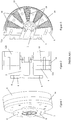
- a known torsional elastic coupling of the type supplied by Geislinger GmbH of Hallwanger Austinsse 3, A-5300 Hallwang/Salzburg, Austria (“Geislinger”) includes a primary member 2 and a secondary member 4 that are elastically connected together by spring packs.
- the primary member 2 includes a flange part 6 with a series of circumferentially spaced openings 8 that enable it to be mechanically secured to the crankshaft of a diesel engine, for example.
- the secondary member 4 consists of an intermediate part 10 that is located between a pair of end plates 12a, 12b and a radially outer clamping ring 14.
- a series of circumferentially-spaced steel spring packs 16 are located in damping chambers 18 provided the intermediate part 12.
- the spring packs 16 are clamped by the intermediate part 10 at their radially outer ends and their radially inner ends are located in carefully machined grooves or slots (not shown) provided in the primary member 2.
- the damping chambers 18 are filled with viscous working fluid, typically engine oil that is circulated from the diesel engine.
- the damping chambers 18 are connected together by narrow passageways that are located adjacent the outer surface of the primary member 2. Relative movement between the primary and secondary members 2, 4 causes the spring packs 16 to bend and forces the viscous working fluid from one damping chamber to another to dampen torsional vibrations.
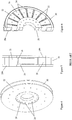
- a known torsional elastic damper of the type supplied by Geislinger includes a primary member 20 and a secondary member 22 that are elastically connected together by spring packs.
- the damper and the coupling have different applications, they have a similar design.
- the primary member 20 of the damper is adapted to be mechanically secured to either input or output components.
- the primary member 20 includes a series of circumferentially spaced openings 24 that enable it to be mechanically secured to the secondary member 4 of the coupling or directly to the crankshaft of a diesel engine, for example, in a situation where the damper is used in isolation.
- the secondary member 22 consists of an intermediate part 26 that is located between a pair of end plates 28a, 28b and a radially outer clamping ring 30.
- a series of circumferentially-spaced steel spring packs 32 are located in damping chambers 34 provided the intermediate part 26.
- the spring packs 32 are clamped by the intermediate part 26 at their radially outer ends and their radially inner ends are located in carefully machined grooves or slots (not shown) provided in the primary member 20.
- the damping chambers 34 are filled with viscous working fluid, typically engine oil that is circulated from the diesel engine.
- the damping chambers 34 are connected together by narrow passageways that are located adjacent the outer surface of the primary member 20. Relative movement between the primary and secondary members 20, 22 causes the spring packs 32 to bend and forces the viscous working fluid from one damping chamber to another to dampen torsional vibrations.
- the damping is determined by the passageways which connect the damping chambers.
- the torsional elastic coupling and damper may be used in combination and mounted between the crankshaft of a diesel engine, for example, and the rotatable shaft of a rotating electrical machine. More particularly, the flange part 6 of the primary member 2 of the coupling is mechanically secured to the crankshaft and the secondary member 4 of the coupling is mechanically secured to the primary member 20 of the damper.
- the primary member 20 of the damper is mechanically secured to the driven end of the rotatable shaft by means of a flange. Torque from the crankshaft is transferred to the driven end of the rotatable shaft by means of the coupling and damper, which both serve to dampen any torsional vibrations in the rotatable shaft.
- the secondary member 22 of the damper is not mechanically secured to any other component and acts as a force/torque transfer mechanism to the spring sets.
- Figures 7 and 8 show how a torsional elastic coupling and damper can be integrated into a rotating electrical machine in accordance with the present invention.
- a generator 100 consists of a stator assembly 102, a rotor assembly 104 (e.g. a rotor core pack) and a rotatable shaft 106.
- the rotatable shaft 106 is supported at its non-driven end by a bearing 108.
- a bearing 110 is located between the rotor assembly 104 and the rotatable shaft 106 and supports the rotor assembly 104 in the radial and axial directions. It will be readily appreciated that the rotor assembly 104 is not fixedly mounted to the rotatable shaft 106 and no torque is transferred directly from the rotatable shaft to the rotor assembly.
- the bearing 110 allows relative torsional rotation between the rotor assembly 104 and the rotatable shaft 106.
- the rotor assembly 104 is concentric with the rotatable shaft 106 and is mounted for rotation within the stator assembly 102.
- An integrated torsional vibration damper (TVD) 200 consists of a torsional elastic coupling 202 of the type shown in Figures 1 to 3 and a torsional elastic damper 204 of the type shown in Figures 4 to 6 .
- the flange part 6 of the primary member 2 of the coupling 202 is mechanically secured to the crankshaft (not shown) of a diesel engine, for example.
- the secondary member 4 of the coupling 202 is mechanically secured to the primary member 20 of the damper 204.
- the primary member 20 of the damper 204 is mechanically secured to the driven end of the rotatable shaft 102 by means of a flange 112. Torque from the crankshaft (not shown) of the diesel engine is transferred to the driven end of the rotatable shaft 106 by means of the elastically connected primary and secondary members 2, 4 of the coupling 202, the primary member 20 of the damper 204 and the flange 112. Torsional vibrations between the crankshaft (not shown) of the diesel engine and the rotatable shaft 106 are therefore damped by the coupling 202.
- the secondary member 22 of the damper 204 is mechanically secured to an end of the rotor assembly 102 by means of a flange 114.
- the flange 114 can be omitted such that the rotor assembly 102 is connected directly to the secondary member 22 of the damper 204.
- Torque from the crankshaft (not shown) of the diesel engine is transferred to the driven end of the rotor assembly 104 by means of the elastically connected primary and secondary members 2, 4 of the coupling, the elastically connected primary and secondary members 20, 22 and the flange 114. Torsional vibrations between the rotatable shaft 106 and the rotor assembly 104 are therefore damped by the damper 204.
- a coolant fluid such as MIDEL and its equivalents is circulated along a coolant circuit provided by passageways 116a, 116b in the rotatable shaft 106.
- the coolant fluid is supplied to, and removed from, the rotatable shaft 106 through a collar assembly 118.
- the coolant fluid is supplied into the coupling 202 and damper 204 of the integrated TVD 200 through openings provided in the flange 112.
- the coolant fluid is therefore circulated through the damping chambers 18, 34 provided in the intermediate parts 12, 26 of the coupling and damper, respectively, where it acts as the viscous working fluid for the integrated TVD 200.
- coolant fluid instead of engine oil circulated from the diesel engine because it has a lower operating temperature (about 40°C as opposed to about 80°C for engine oil) and it does not contain contaminant particles.
- the absence of any contaminant particles will reduce the amount wear in the integrated torsional vibration assembly and increase its reliability.
- the generator 100 is air-cooled then engine oil can be circulated from the diesel engine in the usual way.
- the flow of coolant fluid (or engine oil) within the integrated TVD 200 can be controlled to change the level of damping that is applied to the rotatable shaft 106 by the integrated TVD. This can be achieved using any suitable flow restriction valves, control orifices or actuators (not shown) employing mechanical or electronic control.
- the flow restriction valves can be located within the integrated TVD in the case where the rotor assembly is cooled by a circulating coolant fluid such as MIDEL and either internally or externally of the generator where the rotor assembly is air-cooled. Internally fitted flow restriction valves will typically be controlled mechanically (e.g.
- thermostatic, centrifugal speed and pressure control methods can also be controlled electronically by providing control signals to the flow restriction valves using either wireless or wired arrangements (e.g. using slip rings).
- Externally fitted flow restriction valves will typically be controlled electronically by providing control signals from a diesel engine controller or generator controller as appropriate.
- the integrated TVD 200 can be used as a tuned mass damper to control the critical speed frequencies of the rotatable shaft.
- the rotating electrical machine can be a motor such that the flange 6 of the coupling 202 is mechanically secured to a driven load such as the propeller shaft of a marine propulsion motor, for example.
Landscapes
- Engineering & Computer Science (AREA)
- General Engineering & Computer Science (AREA)
- Physics & Mathematics (AREA)
- Acoustics & Sound (AREA)
- Aviation & Aerospace Engineering (AREA)
- Mechanical Engineering (AREA)
- Power Engineering (AREA)
- Connection Of Motors, Electrical Generators, Mechanical Devices, And The Like (AREA)
Claims (13)
- Machine électrique rotative (100) comprenant :un arbre rotatif (106) ;un ensemble de rotor (104) concentrique avec l'arbre rotatif (106) et comportant une première extrémité et une deuxième extrémité ; etun amortisseur visqueux de vibrations de torsion (200) qui emploie un fluide de travail visqueux pour fournir un amortissement mécanique, l'amortisseur de vibrations de torsion (200) comportant un amortisseur (204) ayant un élément principal (20) qui est monté sur l'arbre rotatif (106) et un élément secondaire (22) relié de manière élastique à l'élément principal (20) par un ou plusieurs ensembles de ressorts (32) et qui est monté sur la première extrémité de l'ensemble de rotor (104), l'élément principal (20) étant en outre adapté pour être monté sur un arbre menant d'un moteur principal ou une charge menée, éventuellement par l'intermédiaire d'un accouplement (202), caractérisée en ce que l'ensemble de rotor (104) n'est pas monté de manière fixe directement sur l'arbre rotatif (106), de sorte que les vibrations de torsion entre l'arbre rotatif (106) et l'ensemble de rotor (104) sont amorties par l'amortisseur (204).
- Machine électrique rotative (100) selon la revendication 1, comprenant en outre un palier (110) entre l'ensemble de rotor (104) et l'arbre rotatif (106).
- Machine électrique rotative (100) selon la revendication 1, comprenant en outre un deuxième amortisseur de vibrations de torsion pour fournir un amortissement mécanique monté sur l'arbre rotatif, l'ensemble de rotor étant monté à la deuxième extrémité sur le deuxième amortisseur de vibrations de torsion.
- Machine électrique rotative (100) selon la revendication 3, dans laquelle les premier et deuxième amortisseurs de vibrations de torsion sont des amortisseurs visqueux qui emploient un fluide de travail visqueux.
- Machine électrique rotative (100) selon l'une quelconque des revendications précédentes, comprenant en outre un circuit de refroidissement (116a, 116b) dans lequel on fait circuler un fluide de refroidissement, le fluide de travail visqueux étant le fluide de refroidissement.
- Machine électrique rotative (100) selon l'une quelconque des revendications précédentes, dans laquelle l'amortisseur de vibrations de torsion (200) est monté de manière fixe sur l'arbre rotatif (106).
- Machine électrique rotative (100) selon l'une quelconque des revendications 1 à 5, dans laquelle l'amortisseur de vibrations de torsion est monté sur l'arbre rotatif par l'intermédiaire d'un mécanisme à ressort et amortisseur pour former un amortisseur de masse accordé.
- Machine électrique rotative (100) selon l'une quelconque des revendications précédentes, dans laquelle l'amortisseur de vibrations de torsion (200) comporte un accouplement (202) ayant un élément principal (2) adapté pour être monté sur un arbre menant d'un moteur principal ou une charge menée et un élément secondaire (4) relié de manière élastique à l'élément principal (2) par un ou plusieurs ensembles de ressorts (16).
- Machine électrique rotative (100) selon la revendication 8, dans laquelle l'élément principal (20) de l'amortisseur (204) est en outre adapté pour être monté sur l'élément secondaire (4) de l'accouplement (202).
- Machine électrique rotative (100) selon l'une quelconque des revendications précédentes, comprenant en outre un ensemble de stator (102).
- Groupe électrogène comprenant :une machine électrique rotative (100) selon l'une quelconque des revendications précédentes ; etun moteur principal adapté pour appliquer un couple à l'arbre rotatif (106) de la machine électrique (100) au moyen de l'amortisseur de vibrations de torsion (200).
- Groupe moteur comprenant :une machine électrique rotative selon l'une quelconque des revendications 1 à 10 ; etune charge menée adaptée pour recevoir un coupe de l'arbre rotatif de la machine électrique au moyen de l'amortisseur de vibrations de torsion.
- Procédé de commande d'un amortisseur visqueux de vibrations de torsion (200) monté sur l'arbre rotatif (106) d'une machine électrique rotative (100) selon la revendication 1, le procédé comprenant l'étape consistant à commander l'écoulement de fluide de travail visqueux dans l'amortisseur visqueux de vibrations de torsion (200) pour modifier le niveau d'amortissement qui est appliqué à l'arbre rotatif (106).
Priority Applications (1)
| Application Number | Priority Date | Filing Date | Title |
|---|---|---|---|
| EP10001154.3A EP2218940B1 (fr) | 2009-02-11 | 2010-02-04 | Machines électriques rotatives |
Applications Claiming Priority (2)
| Application Number | Priority Date | Filing Date | Title |
|---|---|---|---|
| EP09001871A EP2218939A1 (fr) | 2009-02-11 | 2009-02-11 | Machines électriques rotatives |
| EP10001154.3A EP2218940B1 (fr) | 2009-02-11 | 2010-02-04 | Machines électriques rotatives |
Publications (2)
| Publication Number | Publication Date |
|---|---|
| EP2218940A1 EP2218940A1 (fr) | 2010-08-18 |
| EP2218940B1 true EP2218940B1 (fr) | 2018-08-22 |
Family
ID=40863430
Family Applications (2)
| Application Number | Title | Priority Date | Filing Date |
|---|---|---|---|
| EP09001871A Withdrawn EP2218939A1 (fr) | 2009-02-11 | 2009-02-11 | Machines électriques rotatives |
| EP10001154.3A Not-in-force EP2218940B1 (fr) | 2009-02-11 | 2010-02-04 | Machines électriques rotatives |
Family Applications Before (1)
| Application Number | Title | Priority Date | Filing Date |
|---|---|---|---|
| EP09001871A Withdrawn EP2218939A1 (fr) | 2009-02-11 | 2009-02-11 | Machines électriques rotatives |
Country Status (3)
| Country | Link |
|---|---|
| US (2) | US8350422B2 (fr) |
| EP (2) | EP2218939A1 (fr) |
| JP (1) | JP5588691B2 (fr) |
Families Citing this family (18)
| Publication number | Priority date | Publication date | Assignee | Title |
|---|---|---|---|---|
| US8044373B2 (en) * | 2007-06-14 | 2011-10-25 | Asml Netherlands B.V. | Lithographic apparatus and device manufacturing method |
| EP2458256A1 (fr) * | 2010-11-30 | 2012-05-30 | Converteam Technology Ltd | Isolation d'un composant cryogénique |
| US20120214605A1 (en) * | 2011-02-21 | 2012-08-23 | General Electric Company | Gas Turbine Engine Generator System with Torsional Damping Coupling |
| EP2726353B1 (fr) | 2011-06-28 | 2020-10-07 | Schaeffler Technologies AG & Co. KG | Chaîne cinématique hybride dotée d'un amortissement actif de vibrations de torsion et procédé d'amortissement actif de vibrations de torsion |
| NO334163B1 (no) | 2012-03-30 | 2013-12-23 | Techni Holding As | Torsjonskompensator |
| WO2014206416A1 (fr) * | 2013-06-24 | 2014-12-31 | Flsmidth A/S | Presse à rouleaux à grande vitesse |
| US20170114664A1 (en) | 2015-10-23 | 2017-04-27 | General Electric Company | Torsional damping for gas turbine engines |
| US9938853B2 (en) * | 2015-10-23 | 2018-04-10 | General Electric Company | Torsional damping for gas turbine engines |
| EP3472925B1 (fr) * | 2016-06-20 | 2022-02-16 | Nuovo Pignone Tecnologie SrL | Actuateurs électriques pour reduction de vibrations de torsion dans des systèmes turbomachines |
| GB2552678B (en) * | 2016-08-02 | 2019-04-03 | Integral Powertrain Ltd | A rotary device, a motor and a method of cooling a motor |
| DE102017220422B4 (de) | 2017-11-16 | 2024-10-10 | Vitesco Technologies GmbH | Rotor für eine elektrische Maschine |
| DE102018205106B4 (de) | 2018-04-05 | 2023-02-02 | Vitesco Technologies Germany Gmbh | Rotor für eine elektrische Maschine mit integriertem Radial- und Axialschwingungstilger |
| US11097849B2 (en) | 2018-09-10 | 2021-08-24 | General Electric Company | Aircraft having an aft engine |
| US11033146B2 (en) | 2019-02-25 | 2021-06-15 | Sharkninja Operating Llc | Cooking device and components thereof |
| US11539316B2 (en) | 2019-07-30 | 2022-12-27 | General Electric Company | Active stability control of compression systems utilizing electric machines |
| DE102020114608A1 (de) | 2020-06-02 | 2021-12-02 | Winkelmann Powertrain Components GmbH & Co. KG. | Rotor |
| DE102022101972B3 (de) | 2022-01-28 | 2023-07-06 | Schaeffler Technologies AG & Co. KG | Rotoranordnung für eine elektrische Axialflussmaschine und elektrische Axialflussmaschine |
| DE102024110599A1 (de) * | 2024-04-16 | 2025-10-16 | Schaeffler Technologies AG & Co. KG | Elastomerdämpfer zur Geräuschreduzierung in Hybridgetrieben und E-Motoren |
Family Cites Families (18)
| Publication number | Priority date | Publication date | Assignee | Title |
|---|---|---|---|---|
| DE3515928C2 (de) * | 1985-05-03 | 1994-04-14 | Fichtel & Sachs Ag | Geteiltes Schwungrad für eine Brennkraftmaschine |
| JPH0678650U (ja) * | 1993-04-13 | 1994-11-04 | 株式会社三ツ葉電機製作所 | ウオーム減速機付モータ |
| JP3551612B2 (ja) * | 1996-03-22 | 2004-08-11 | 日産自動車株式会社 | カップリング付ダンパ |
| AT405866B (de) * | 1997-09-23 | 1999-12-27 | Geislinger Co Schwingungstechn | Drehschwingungsdämpfer bzw. schwingungsdämpfende und drehelastische kupplung |
| DE19943037B4 (de) * | 1999-09-09 | 2015-09-03 | Zf Friedrichshafen Ag | Antriebssystem |
| DE19943038A1 (de) * | 1999-09-09 | 2001-03-15 | Mannesmann Sachs Ag | Antriebssystem |
| JP4613432B2 (ja) * | 2001-03-15 | 2011-01-19 | 株式会社デンソー | 動力伝達装置 |
| JP2004053008A (ja) * | 2002-05-31 | 2004-02-19 | Fukoku Co Ltd | ビスカスダンパ |
| DE10246227B4 (de) * | 2002-10-04 | 2007-06-14 | Zf Sachs Ag | Antriebseinheit, insbesondere für ein Kraftfahrzeug |
| JP2005237159A (ja) * | 2004-02-23 | 2005-09-02 | Tamagawa Seiki Co Ltd | ブラシレスモータ |
| DE102005031813A1 (de) * | 2005-07-06 | 2007-01-18 | Zf Friedrichshafen Ag | Dämpfungseinrichtung für einen Torsionsschwingungsdämpfer |
| DE102005040769A1 (de) * | 2005-08-29 | 2007-03-01 | Zf Friedrichshafen Ag | Automatisch schaltbares Fahrzeuggetriebe |
| DE102005058531A1 (de) * | 2005-12-08 | 2007-06-14 | Zf Friedrichshafen Ag | Torsionsschwingungsdämpfer |
| DE102006034945A1 (de) * | 2006-07-28 | 2008-04-10 | Zf Friedrichshafen Ag | Antriebsanordnung für ein Hybridfahrzeug |
| US20080099258A1 (en) * | 2006-10-26 | 2008-05-01 | Berhan Michael T | Vented sealed housing assembly for vehicle powertrain |
| DE102008023361A1 (de) * | 2007-05-31 | 2008-12-04 | Luk Lamellen Und Kupplungsbau Beteiligungs Kg | Torsionsschwingungsdämpfer |
| US20090078077A1 (en) * | 2007-09-20 | 2009-03-26 | Horschel Karl G | Centering viscous torsional vibration damper |
| DE102008050054A1 (de) * | 2008-10-01 | 2010-04-08 | Zf Friedrichshafen Ag | Hybridantriebssystem |
-
2009
- 2009-02-11 EP EP09001871A patent/EP2218939A1/fr not_active Withdrawn
-
2010
- 2010-02-03 JP JP2010022385A patent/JP5588691B2/ja not_active Expired - Fee Related
- 2010-02-04 EP EP10001154.3A patent/EP2218940B1/fr not_active Not-in-force
- 2010-02-08 US US12/701,842 patent/US8350422B2/en not_active Expired - Fee Related
-
2012
- 2012-12-12 US US13/711,657 patent/US8669680B2/en not_active Expired - Fee Related
Non-Patent Citations (1)
| Title |
|---|
| None * |
Also Published As
| Publication number | Publication date |
|---|---|
| US20100225121A1 (en) | 2010-09-09 |
| US20130099608A1 (en) | 2013-04-25 |
| JP2010185573A (ja) | 2010-08-26 |
| EP2218939A1 (fr) | 2010-08-18 |
| EP2218940A1 (fr) | 2010-08-18 |
| JP5588691B2 (ja) | 2014-09-10 |
| US8669680B2 (en) | 2014-03-11 |
| US8350422B2 (en) | 2013-01-08 |
Similar Documents
| Publication | Publication Date | Title |
|---|---|---|
| US8350422B2 (en) | Rotating electrical machines | |
| RU2434151C2 (ru) | Устройство привода ротора вспомогательного агрегата газотурбинного двигателя, опора агрегатов для газотурбинного двигателя и газотурбинный двигатель | |
| EP2199641B1 (fr) | Amortisseur de torsion à courant de Foucault pour générateur | |
| EP1495234B1 (fr) | Ensemble palier equipe d'un amortisseur a l'huile | |
| ZA200402008B (en) | Flywheel energy storage systems | |
| US11009085B2 (en) | Electromagnetic clutch for gas turbine accessories | |
| WO2011146303A1 (fr) | Système de support de machine à induction | |
| JP6713865B2 (ja) | トルクコンバータ | |
| CN102649096B (zh) | 用于磨机驱动系统的变速马达 | |
| US7560837B2 (en) | Automotive alternator with rotary magnetic fluctuation suppressor | |
| WO2018012172A1 (fr) | Convertisseur de couple et dispositif de transmission de puissance | |
| KR20250133942A (ko) | 회전자 및 전기 기계 | |
| AU2020232993B2 (en) | Flywheel systems and related methods | |
| EP2386779B1 (fr) | Rotors pour machines électriques | |
| JP2021087329A (ja) | 回転電機 | |
| CN115642753B (zh) | 一种反穿式同轴三支撑的齿轮箱高速转子系统 | |
| KR20250133948A (ko) | 전기 기계, 기계식 자기장 감쇠 메커니즘을 생산하기 위한 방법, 기계식 자기장 감쇠 메커니즘 및 부품 키트 | |
| KR20250166933A (ko) | 회전자 및 전기 기계 | |
| Werner | rotors and sleeve bearings fixed on active motor foot mounts for arbitrary controller | |
| Singhal et al. | Influence of design, manufacturing & installation practices on rotor vibrations of large induction motors used in petrochemical industry | |
| WO2021229332A1 (fr) | Moteur amorti de façon critique ou amorti par cavités | |
| KR20250133408A (ko) | 회전자 및 전기 기계 | |
| HK1230799B (en) | A stator for an electrical machine of a working machine | |
| HK1230800B (en) | A stator for an electrical machine of a working machine |
Legal Events
| Date | Code | Title | Description |
|---|---|---|---|
| PUAI | Public reference made under article 153(3) epc to a published international application that has entered the european phase |
Free format text: ORIGINAL CODE: 0009012 |
|
| AK | Designated contracting states |
Kind code of ref document: A1 Designated state(s): AT BE BG CH CY CZ DE DK EE ES FI FR GB GR HR HU IE IS IT LI LT LU LV MC MK MT NL NO PL PT RO SE SI SK SM TR |
|
| AX | Request for extension of the european patent |
Extension state: AL BA RS |
|
| 17P | Request for examination filed |
Effective date: 20110201 |
|
| RAP1 | Party data changed (applicant data changed or rights of an application transferred) |
Owner name: GE ENERGY POWER CONVERSION TECHNOLOGY LIMITED |
|
| REG | Reference to a national code |
Ref country code: DE Ref legal event code: R079 Ref document number: 602010052889 Country of ref document: DE Free format text: PREVIOUS MAIN CLASS: F16F0015160000 Ipc: H02K0007000000 |
|
| GRAP | Despatch of communication of intention to grant a patent |
Free format text: ORIGINAL CODE: EPIDOSNIGR1 |
|
| STAA | Information on the status of an ep patent application or granted ep patent |
Free format text: STATUS: GRANT OF PATENT IS INTENDED |
|
| RIC1 | Information provided on ipc code assigned before grant |
Ipc: H02K 7/00 20060101AFI20180223BHEP Ipc: F16F 15/16 20060101ALI20180223BHEP |
|
| INTG | Intention to grant announced |
Effective date: 20180323 |
|
| GRAS | Grant fee paid |
Free format text: ORIGINAL CODE: EPIDOSNIGR3 |
|
| GRAA | (expected) grant |
Free format text: ORIGINAL CODE: 0009210 |
|
| STAA | Information on the status of an ep patent application or granted ep patent |
Free format text: STATUS: THE PATENT HAS BEEN GRANTED |
|
| AK | Designated contracting states |
Kind code of ref document: B1 Designated state(s): AT BE BG CH CY CZ DE DK EE ES FI FR GB GR HR HU IE IS IT LI LT LU LV MC MK MT NL NO PL PT RO SE SI SK SM TR |
|
| REG | Reference to a national code |
Ref country code: GB Ref legal event code: FG4D |
|
| REG | Reference to a national code |
Ref country code: CH Ref legal event code: EP |
|
| REG | Reference to a national code |
Ref country code: DE Ref legal event code: R096 Ref document number: 602010052889 Country of ref document: DE |
|
| REG | Reference to a national code |
Ref country code: AT Ref legal event code: REF Ref document number: 1033602 Country of ref document: AT Kind code of ref document: T Effective date: 20180915 |
|
| REG | Reference to a national code |
Ref country code: IE Ref legal event code: FG4D |
|
| REG | Reference to a national code |
Ref country code: NL Ref legal event code: MP Effective date: 20180822 |
|
| REG | Reference to a national code |
Ref country code: LT Ref legal event code: MG4D |
|
| PG25 | Lapsed in a contracting state [announced via postgrant information from national office to epo] |
Ref country code: FI Free format text: LAPSE BECAUSE OF FAILURE TO SUBMIT A TRANSLATION OF THE DESCRIPTION OR TO PAY THE FEE WITHIN THE PRESCRIBED TIME-LIMIT Effective date: 20180822 Ref country code: LT Free format text: LAPSE BECAUSE OF FAILURE TO SUBMIT A TRANSLATION OF THE DESCRIPTION OR TO PAY THE FEE WITHIN THE PRESCRIBED TIME-LIMIT Effective date: 20180822 Ref country code: BG Free format text: LAPSE BECAUSE OF FAILURE TO SUBMIT A TRANSLATION OF THE DESCRIPTION OR TO PAY THE FEE WITHIN THE PRESCRIBED TIME-LIMIT Effective date: 20181122 Ref country code: NL Free format text: LAPSE BECAUSE OF FAILURE TO SUBMIT A TRANSLATION OF THE DESCRIPTION OR TO PAY THE FEE WITHIN THE PRESCRIBED TIME-LIMIT Effective date: 20180822 Ref country code: NO Free format text: LAPSE BECAUSE OF FAILURE TO SUBMIT A TRANSLATION OF THE DESCRIPTION OR TO PAY THE FEE WITHIN THE PRESCRIBED TIME-LIMIT Effective date: 20181122 Ref country code: IS Free format text: LAPSE BECAUSE OF FAILURE TO SUBMIT A TRANSLATION OF THE DESCRIPTION OR TO PAY THE FEE WITHIN THE PRESCRIBED TIME-LIMIT Effective date: 20181222 Ref country code: GR Free format text: LAPSE BECAUSE OF FAILURE TO SUBMIT A TRANSLATION OF THE DESCRIPTION OR TO PAY THE FEE WITHIN THE PRESCRIBED TIME-LIMIT Effective date: 20181123 Ref country code: SE Free format text: LAPSE BECAUSE OF FAILURE TO SUBMIT A TRANSLATION OF THE DESCRIPTION OR TO PAY THE FEE WITHIN THE PRESCRIBED TIME-LIMIT Effective date: 20180822 |
|
| REG | Reference to a national code |
Ref country code: AT Ref legal event code: MK05 Ref document number: 1033602 Country of ref document: AT Kind code of ref document: T Effective date: 20180822 |
|
| PG25 | Lapsed in a contracting state [announced via postgrant information from national office to epo] |
Ref country code: HR Free format text: LAPSE BECAUSE OF FAILURE TO SUBMIT A TRANSLATION OF THE DESCRIPTION OR TO PAY THE FEE WITHIN THE PRESCRIBED TIME-LIMIT Effective date: 20180822 Ref country code: LV Free format text: LAPSE BECAUSE OF FAILURE TO SUBMIT A TRANSLATION OF THE DESCRIPTION OR TO PAY THE FEE WITHIN THE PRESCRIBED TIME-LIMIT Effective date: 20180822 Ref country code: ES Free format text: LAPSE BECAUSE OF FAILURE TO SUBMIT A TRANSLATION OF THE DESCRIPTION OR TO PAY THE FEE WITHIN THE PRESCRIBED TIME-LIMIT Effective date: 20180822 |
|
| PG25 | Lapsed in a contracting state [announced via postgrant information from national office to epo] |
Ref country code: CZ Free format text: LAPSE BECAUSE OF FAILURE TO SUBMIT A TRANSLATION OF THE DESCRIPTION OR TO PAY THE FEE WITHIN THE PRESCRIBED TIME-LIMIT Effective date: 20180822 Ref country code: IT Free format text: LAPSE BECAUSE OF FAILURE TO SUBMIT A TRANSLATION OF THE DESCRIPTION OR TO PAY THE FEE WITHIN THE PRESCRIBED TIME-LIMIT Effective date: 20180822 Ref country code: PL Free format text: LAPSE BECAUSE OF FAILURE TO SUBMIT A TRANSLATION OF THE DESCRIPTION OR TO PAY THE FEE WITHIN THE PRESCRIBED TIME-LIMIT Effective date: 20180822 Ref country code: AT Free format text: LAPSE BECAUSE OF FAILURE TO SUBMIT A TRANSLATION OF THE DESCRIPTION OR TO PAY THE FEE WITHIN THE PRESCRIBED TIME-LIMIT Effective date: 20180822 Ref country code: EE Free format text: LAPSE BECAUSE OF FAILURE TO SUBMIT A TRANSLATION OF THE DESCRIPTION OR TO PAY THE FEE WITHIN THE PRESCRIBED TIME-LIMIT Effective date: 20180822 Ref country code: RO Free format text: LAPSE BECAUSE OF FAILURE TO SUBMIT A TRANSLATION OF THE DESCRIPTION OR TO PAY THE FEE WITHIN THE PRESCRIBED TIME-LIMIT Effective date: 20180822 |
|
| PGFP | Annual fee paid to national office [announced via postgrant information from national office to epo] |
Ref country code: GB Payment date: 20190125 Year of fee payment: 10 Ref country code: FR Payment date: 20190123 Year of fee payment: 10 Ref country code: DE Payment date: 20190122 Year of fee payment: 10 |
|
| REG | Reference to a national code |
Ref country code: DE Ref legal event code: R097 Ref document number: 602010052889 Country of ref document: DE |
|
| PG25 | Lapsed in a contracting state [announced via postgrant information from national office to epo] |
Ref country code: DK Free format text: LAPSE BECAUSE OF FAILURE TO SUBMIT A TRANSLATION OF THE DESCRIPTION OR TO PAY THE FEE WITHIN THE PRESCRIBED TIME-LIMIT Effective date: 20180822 Ref country code: SM Free format text: LAPSE BECAUSE OF FAILURE TO SUBMIT A TRANSLATION OF THE DESCRIPTION OR TO PAY THE FEE WITHIN THE PRESCRIBED TIME-LIMIT Effective date: 20180822 Ref country code: SK Free format text: LAPSE BECAUSE OF FAILURE TO SUBMIT A TRANSLATION OF THE DESCRIPTION OR TO PAY THE FEE WITHIN THE PRESCRIBED TIME-LIMIT Effective date: 20180822 |
|
| PLBE | No opposition filed within time limit |
Free format text: ORIGINAL CODE: 0009261 |
|
| STAA | Information on the status of an ep patent application or granted ep patent |
Free format text: STATUS: NO OPPOSITION FILED WITHIN TIME LIMIT |
|
| 26N | No opposition filed |
Effective date: 20190523 |
|
| PG25 | Lapsed in a contracting state [announced via postgrant information from national office to epo] |
Ref country code: SI Free format text: LAPSE BECAUSE OF FAILURE TO SUBMIT A TRANSLATION OF THE DESCRIPTION OR TO PAY THE FEE WITHIN THE PRESCRIBED TIME-LIMIT Effective date: 20180822 |
|
| REG | Reference to a national code |
Ref country code: CH Ref legal event code: PL |
|
| PG25 | Lapsed in a contracting state [announced via postgrant information from national office to epo] |
Ref country code: MC Free format text: LAPSE BECAUSE OF FAILURE TO SUBMIT A TRANSLATION OF THE DESCRIPTION OR TO PAY THE FEE WITHIN THE PRESCRIBED TIME-LIMIT Effective date: 20180822 Ref country code: LU Free format text: LAPSE BECAUSE OF NON-PAYMENT OF DUE FEES Effective date: 20190204 |
|
| REG | Reference to a national code |
Ref country code: BE Ref legal event code: MM Effective date: 20190228 |
|
| REG | Reference to a national code |
Ref country code: IE Ref legal event code: MM4A |
|
| PG25 | Lapsed in a contracting state [announced via postgrant information from national office to epo] |
Ref country code: CH Free format text: LAPSE BECAUSE OF NON-PAYMENT OF DUE FEES Effective date: 20190228 Ref country code: LI Free format text: LAPSE BECAUSE OF NON-PAYMENT OF DUE FEES Effective date: 20190228 |
|
| PG25 | Lapsed in a contracting state [announced via postgrant information from national office to epo] |
Ref country code: IE Free format text: LAPSE BECAUSE OF NON-PAYMENT OF DUE FEES Effective date: 20190204 |
|
| PG25 | Lapsed in a contracting state [announced via postgrant information from national office to epo] |
Ref country code: BE Free format text: LAPSE BECAUSE OF NON-PAYMENT OF DUE FEES Effective date: 20190228 |
|
| PG25 | Lapsed in a contracting state [announced via postgrant information from national office to epo] |
Ref country code: TR Free format text: LAPSE BECAUSE OF FAILURE TO SUBMIT A TRANSLATION OF THE DESCRIPTION OR TO PAY THE FEE WITHIN THE PRESCRIBED TIME-LIMIT Effective date: 20180822 |
|
| PG25 | Lapsed in a contracting state [announced via postgrant information from national office to epo] |
Ref country code: PT Free format text: LAPSE BECAUSE OF FAILURE TO SUBMIT A TRANSLATION OF THE DESCRIPTION OR TO PAY THE FEE WITHIN THE PRESCRIBED TIME-LIMIT Effective date: 20181222 Ref country code: MT Free format text: LAPSE BECAUSE OF NON-PAYMENT OF DUE FEES Effective date: 20190204 |
|
| REG | Reference to a national code |
Ref country code: DE Ref legal event code: R119 Ref document number: 602010052889 Country of ref document: DE |
|
| GBPC | Gb: european patent ceased through non-payment of renewal fee |
Effective date: 20200204 |
|
| PG25 | Lapsed in a contracting state [announced via postgrant information from national office to epo] |
Ref country code: GB Free format text: LAPSE BECAUSE OF NON-PAYMENT OF DUE FEES Effective date: 20200204 Ref country code: FR Free format text: LAPSE BECAUSE OF NON-PAYMENT OF DUE FEES Effective date: 20200229 Ref country code: DE Free format text: LAPSE BECAUSE OF NON-PAYMENT OF DUE FEES Effective date: 20200901 |
|
| PG25 | Lapsed in a contracting state [announced via postgrant information from national office to epo] |
Ref country code: CY Free format text: LAPSE BECAUSE OF FAILURE TO SUBMIT A TRANSLATION OF THE DESCRIPTION OR TO PAY THE FEE WITHIN THE PRESCRIBED TIME-LIMIT Effective date: 20180822 |
|
| PG25 | Lapsed in a contracting state [announced via postgrant information from national office to epo] |
Ref country code: HU Free format text: LAPSE BECAUSE OF FAILURE TO SUBMIT A TRANSLATION OF THE DESCRIPTION OR TO PAY THE FEE WITHIN THE PRESCRIBED TIME-LIMIT; INVALID AB INITIO Effective date: 20100204 |
|
| PG25 | Lapsed in a contracting state [announced via postgrant information from national office to epo] |
Ref country code: MK Free format text: LAPSE BECAUSE OF FAILURE TO SUBMIT A TRANSLATION OF THE DESCRIPTION OR TO PAY THE FEE WITHIN THE PRESCRIBED TIME-LIMIT Effective date: 20180822 |