EP2219000A2 - Section de récupérateur pour système de ventilation avec alimentation-échappement - Google Patents
Section de récupérateur pour système de ventilation avec alimentation-échappement Download PDFInfo
- Publication number
- EP2219000A2 EP2219000A2 EP10461503A EP10461503A EP2219000A2 EP 2219000 A2 EP2219000 A2 EP 2219000A2 EP 10461503 A EP10461503 A EP 10461503A EP 10461503 A EP10461503 A EP 10461503A EP 2219000 A2 EP2219000 A2 EP 2219000A2
- Authority
- EP
- European Patent Office
- Prior art keywords
- section
- recuperator
- segments
- collectors
- openings
- Prior art date
- Legal status (The legal status is an assumption and is not a legal conclusion. Google has not performed a legal analysis and makes no representation as to the accuracy of the status listed.)
- Withdrawn
Links
- 238000009423 ventilation Methods 0.000 title claims abstract description 17
- 238000005192 partition Methods 0.000 claims abstract description 24
- 230000009286 beneficial effect Effects 0.000 description 2
- 238000010276 construction Methods 0.000 description 2
- 238000012986 modification Methods 0.000 description 2
- 230000004048 modification Effects 0.000 description 2
- 238000005516 engineering process Methods 0.000 description 1
- 239000002184 metal Substances 0.000 description 1
- 238000007789 sealing Methods 0.000 description 1
Images
Classifications
-
- F—MECHANICAL ENGINEERING; LIGHTING; HEATING; WEAPONS; BLASTING
- F28—HEAT EXCHANGE IN GENERAL
- F28D—HEAT-EXCHANGE APPARATUS, NOT PROVIDED FOR IN ANOTHER SUBCLASS, IN WHICH THE HEAT-EXCHANGE MEDIA DO NOT COME INTO DIRECT CONTACT
- F28D9/00—Heat-exchange apparatus having stationary plate-like or laminated conduit assemblies for both heat-exchange media, the media being in contact with different sides of a conduit wall
-
- F—MECHANICAL ENGINEERING; LIGHTING; HEATING; WEAPONS; BLASTING
- F24—HEATING; RANGES; VENTILATING
- F24F—AIR-CONDITIONING; AIR-HUMIDIFICATION; VENTILATION; USE OF AIR CURRENTS FOR SCREENING
- F24F12/00—Use of energy recovery systems in air conditioning, ventilation or screening
- F24F12/001—Use of energy recovery systems in air conditioning, ventilation or screening with heat-exchange between supplied and exhausted air
- F24F12/006—Use of energy recovery systems in air conditioning, ventilation or screening with heat-exchange between supplied and exhausted air using an air-to-air heat exchanger
-
- Y—GENERAL TAGGING OF NEW TECHNOLOGICAL DEVELOPMENTS; GENERAL TAGGING OF CROSS-SECTIONAL TECHNOLOGIES SPANNING OVER SEVERAL SECTIONS OF THE IPC; TECHNICAL SUBJECTS COVERED BY FORMER USPC CROSS-REFERENCE ART COLLECTIONS [XRACs] AND DIGESTS
- Y02—TECHNOLOGIES OR APPLICATIONS FOR MITIGATION OR ADAPTATION AGAINST CLIMATE CHANGE
- Y02B—CLIMATE CHANGE MITIGATION TECHNOLOGIES RELATED TO BUILDINGS, e.g. HOUSING, HOUSE APPLIANCES OR RELATED END-USER APPLICATIONS
- Y02B30/00—Energy efficient heating, ventilation or air conditioning [HVAC]
- Y02B30/56—Heat recovery units
Definitions
- the subject of the present invention is the recuperator's section for the intake and exhaust ventilation centre.
- recuperators plate heat exchangers
- the constructions of intake and exhaust ventilation centres are employed in which the recuperators' plates are vertical or horizontal but, at the same time, they are always parallel to the longitudinal axis of the ventilation centre.
- Such a manner of placing the recuperator in the ventilation centre is the cause of stagnation in development of counter-current recuperators.
- Counter - current recuperators such as, for example, GS-type recuperators
- the counter-current recuperators have considerably better characteristics than single as well as double cross-flow recuperators due to a more advantageous temperature field.
- the above has been demonstrated, among others, in the publication entitled: "rely vonvierstrom - implace zu verdoppelten funnelsromwarme (2004) HLH Bd 58 (2007) No. 4, pages 89 - 94 .
- recuperators Due to common use of the recuperators' plates that are parallel to the longitudinal axis of the ventilation centre, the manufacturer of the above-mentioned GS recuperators (Klingenburg company located near Munich) has extended its offer by adding four more sizes of the recuperators (GS 62, 80, 95 and 110). Consequently, considerable costs connected with preparation of the instrumentation have been generated. Such costs are avoidable with the use of the design described in the presented invention.
- the extension of the assortment of recuperators is the evidence of regress in development of recuperators because consumption of sheet metal plate per a unit of heat transfer capacity is higher in larger GS-type recuperators (even by 60 % higher than in case of the smallest GS 25 recuperator). It is because the temperature field in the larger GS-type recuperators is more and more similar to the temperature field in the cross-flow recuperators.
- Patent application P - 353 985 presents the system for sealing the heat recuperation chamber in the ventilation system.
- Patent application P - 363 653 presents the system in which the inlet and outlet of each of the both air streams are located on the same side of the section's axis.
- the systems presented in the above-mentioned applications do not include the design that can make it possible to ensure that the inlet and outlet of a given air stream (for example, of a fresh air stream) to/from the section is located on the same side of the section's vertical axis.
- a given air stream for example, of a fresh air stream
- the United States Patent Application US2005236136 presents also the heat exchanger in which the plates of heat accumulating mass are perpendicular to the longitudinal axis of the ventilation centre.
- the two alternative heat accumulating packs have the inlet and outlet of each of the streams of fresh and exhaust air that are located on the opposite sides of the vertical axis of the heat exchanger.
- This solution has a complicated design in which the use of two four-way valves is required.
- the characteristic feature of the recuperator's section according to the invention is that it has at least one pair of parallely arranged segments.
- the inlet-outlet openings of a pair of segments are connected to the space of the lower collector or the upper collector.
- the upper collector and the lower collector are frontally closed on one side.
- the upper collector and the lower collector are connected through the sleeves to the openings in the partitions of the recuperator's section.
- the spaces limited by the section's external walls and the partition separating these walls form two collectors for segment openings that are not housed by the lower collector and the upper collector.
- each lower collector is mounted on the frame with brackets on which the lower, external edges of the external segments are based.
- recuperator's section includes the recuperator's segments in which the fresh air stream intersects with the stream of exhaust air and when the sleeve connecting the upper collector with the opening in the partition is located on the side of the section opposite to the side on which the sleeve connecting the lower collector with the opening in the section's partition is located.
- recuperator's section includes the recuperator's segments in which the fresh air stream does not intersect with the stream of exhaust air and when the sleeve connecting the upper collector with the front partition of the section is located on the same side of the section with the sleeve connecting the lower collector with the opening in the section's partition.
- the invention enables the use of commonly available recuperators in which the fresh air stream intersects with the stream of exhaust air.
- the invention enables also the combination of small counter-current recuperators that are available on the market into a unit of recuperators for the needs of large ventilation centres. Such a unit of recuperators does not lose the advantages of the counter-current recuperator. Consequently, the invention enables easy and common use of the available counter-current recuperators.
- the unit formed by the recuperator's segments has a compact and modular construction that can be slid outside the section's housing and is easy to maintain thanks to the use of small recuperators' segments.
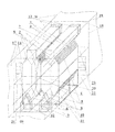
- Section 1 of the intake and exhaust ventilation centre (16) has a plate heat exchanger (recuperator) 2 consisting of two pairs of segments 5 that are positioned side by side.
- the segments 5 have plates 3 that are positioned perpendicularly with regard to longitudinal axis 4 of the ventilation centre.
- the inlet - outlet openings whose area is limited by the contact surface of segments 5 of a given pair and the vertex edge of these segments 5, are connected with the internal space of the channel-type lower collector 6 or upper collector 7.
- Lower collectors 6 are mounted on frame 9 that has vertical brackets 10 on which lower, external edges of external segments 5 are based. Thanks to such a solution, frame 9 and lower collectors 6 form base 11 on which recuperator 2 is supported.
- One of the streams for example, the fresh air stream, flows along the route on which the following elements are located: sleeves 12, collectors 6, gaps between the plates 3 of segments 5, upper space 19 of section 1, damper 21.
- the other stream for example, the stream of air discharged to atmosphere flows along the following route: sleeves 13, collectors 7, gaps between the plates 3, lower space 22, damper 23.
Landscapes
- Engineering & Computer Science (AREA)
- Mechanical Engineering (AREA)
- General Engineering & Computer Science (AREA)
- Physics & Mathematics (AREA)
- Thermal Sciences (AREA)
- Chemical & Material Sciences (AREA)
- Combustion & Propulsion (AREA)
- Heat-Exchange Devices With Radiators And Conduit Assemblies (AREA)
Applications Claiming Priority (1)
| Application Number | Priority Date | Filing Date | Title |
|---|---|---|---|
| PL387283A PL209215B1 (pl) | 2009-02-16 | 2009-02-16 | Sekcja rekuperatora dla nawiewno-wyciągowej centrali wentylacyjnej |
Publications (2)
| Publication Number | Publication Date |
|---|---|
| EP2219000A2 true EP2219000A2 (fr) | 2010-08-18 |
| EP2219000A3 EP2219000A3 (fr) | 2014-01-15 |
Family
ID=42169295
Family Applications (1)
| Application Number | Title | Priority Date | Filing Date |
|---|---|---|---|
| EP10461503.4A Withdrawn EP2219000A3 (fr) | 2009-02-16 | 2010-02-16 | Section de récupérateur pour système de ventilation avec alimentation-échappement |
Country Status (2)
| Country | Link |
|---|---|
| EP (1) | EP2219000A3 (fr) |
| PL (1) | PL209215B1 (fr) |
Cited By (1)
| Publication number | Priority date | Publication date | Assignee | Title |
|---|---|---|---|---|
| FR3083592A1 (fr) * | 2018-07-06 | 2020-01-10 | Commissariat A L'energie Atomique Et Aux Energies Alternatives | Dispositif de recuperation d'energie entre fluides gazeux, et procede de fabrication d'un tel dispositif |
Citations (3)
| Publication number | Priority date | Publication date | Assignee | Title |
|---|---|---|---|---|
| PL353985A1 (en) | 2001-05-23 | 2002-12-02 | Vallox Oy | Sealing system for a heat recuperation chember |
| PL363653A1 (pl) | 2003-11-24 | 2005-05-30 | Jakobczak Antoni | Układ urządzenia wentylacyjnego z wymiennikiem doodzyskiwania ciepła |
| US20050236136A1 (en) | 2002-03-11 | 2005-10-27 | Level Holding B.V. | Heat recuperator with frost protection |
Family Cites Families (1)
| Publication number | Priority date | Publication date | Assignee | Title |
|---|---|---|---|---|
| FR2315674A1 (fr) * | 1975-06-27 | 1977-01-21 | Ferodo Sa | Perfectionnements aux echangeurs de chaleur a plaques |
-
2009
- 2009-02-16 PL PL387283A patent/PL209215B1/pl unknown
-
2010
- 2010-02-16 EP EP10461503.4A patent/EP2219000A3/fr not_active Withdrawn
Patent Citations (3)
| Publication number | Priority date | Publication date | Assignee | Title |
|---|---|---|---|---|
| PL353985A1 (en) | 2001-05-23 | 2002-12-02 | Vallox Oy | Sealing system for a heat recuperation chember |
| US20050236136A1 (en) | 2002-03-11 | 2005-10-27 | Level Holding B.V. | Heat recuperator with frost protection |
| PL363653A1 (pl) | 2003-11-24 | 2005-05-30 | Jakobczak Antoni | Układ urządzenia wentylacyjnego z wymiennikiem doodzyskiwania ciepła |
Non-Patent Citations (1)
| Title |
|---|
| "Vorteile von Gegenstrom - im Vergleich zu verdoppelten Kreuzsromwarmetauschen", HLH, vol. 58, no. 4, 2007, pages 89 - 94 |
Cited By (2)
| Publication number | Priority date | Publication date | Assignee | Title |
|---|---|---|---|---|
| FR3083592A1 (fr) * | 2018-07-06 | 2020-01-10 | Commissariat A L'energie Atomique Et Aux Energies Alternatives | Dispositif de recuperation d'energie entre fluides gazeux, et procede de fabrication d'un tel dispositif |
| EP3594586A1 (fr) * | 2018-07-06 | 2020-01-15 | Commissariat à l'énergie atomique et aux énergies alternatives | Dispositif de récuperation d'énergie entre fluides gazeux et procédé de fabrication d'un tel dispositif |
Also Published As
| Publication number | Publication date |
|---|---|
| PL387283A1 (pl) | 2010-08-30 |
| PL209215B1 (pl) | 2011-08-31 |
| EP2219000A3 (fr) | 2014-01-15 |
Similar Documents
| Publication | Publication Date | Title |
|---|---|---|
| US6949131B2 (en) | Ventilator or ventilating apparatus with thermal exchanger and air filter | |
| WO2008125309A3 (fr) | Échangeur de chaleur | |
| CN101511619A (zh) | 车用空调装置的排水构造 | |
| KR101401443B1 (ko) | 맞흐름식 열교환장치 | |
| JP2010504244A5 (fr) | ||
| JP5743685B2 (ja) | 冷凍空調システム | |
| CN209197072U (zh) | 新风净化装置 | |
| CN111981660A (zh) | 一种纯逆流显热交换器 | |
| CN207702669U (zh) | 吊顶式低噪音高效过滤新风净化机 | |
| CN208687946U (zh) | 风道系统及空调器 | |
| US7565923B2 (en) | Rotary total heat exchange apparatus | |
| KR101995387B1 (ko) | 필터 내장형 전열교환소자 | |
| CN202188564U (zh) | 多功能室内环境调节机 | |
| CN201377863Y (zh) | 两排管大焓差风机盘管机组 | |
| EP2219000A3 (fr) | Section de récupérateur pour système de ventilation avec alimentation-échappement | |
| CN201621904U (zh) | 一种工业中央空调用水换热器 | |
| CN208901613U (zh) | 一种双通双滤换热模块组 | |
| CN219656243U (zh) | 一种新风机 | |
| CN219976801U (zh) | 一种换热器 | |
| ES2454416T3 (es) | Intercambiador de calor especialmente para vehículo automóvil | |
| CN212299195U (zh) | 表冷器及空调器 | |
| JP2006105516A (ja) | 建物の換気構造 | |
| CN217560039U (zh) | 一种轻薄型新风机的净化交换系统 | |
| CN224188732U (zh) | 一种洁净室暖通送排风余热回收换热器 | |
| EP2719961A3 (fr) | Unité d'intérieur pour climatiseur |
Legal Events
| Date | Code | Title | Description |
|---|---|---|---|
| PUAI | Public reference made under article 153(3) epc to a published international application that has entered the european phase |
Free format text: ORIGINAL CODE: 0009012 |
|
| AK | Designated contracting states |
Kind code of ref document: A2 Designated state(s): AT BE BG CH CY CZ DE DK EE ES FI FR GB GR HR HU IE IS IT LI LT LU LV MC MK MT NL NO PL PT RO SE SI SK SM TR |
|
| AX | Request for extension of the european patent |
Extension state: AL BA RS |
|
| PUAL | Search report despatched |
Free format text: ORIGINAL CODE: 0009013 |
|
| AK | Designated contracting states |
Kind code of ref document: A3 Designated state(s): AT BE BG CH CY CZ DE DK EE ES FI FR GB GR HR HU IE IS IT LI LT LU LV MC MK MT NL NO PL PT RO SE SI SK SM TR |
|
| AX | Request for extension of the european patent |
Extension state: AL BA RS |
|
| RIC1 | Information provided on ipc code assigned before grant |
Ipc: F28D 9/00 20060101AFI20131206BHEP Ipc: F24F 12/00 20060101ALI20131206BHEP |
|
| RBV | Designated contracting states (corrected) |
Designated state(s): AT BE BG CH CY CZ DE DK EE ES FI FR GB GR HR HU IE IS IT LI LT LU LV MC MK MT NL NO PL PT RO SE SI SK SM TR |
|
| 17P | Request for examination filed |
Effective date: 20140703 |
|
| 17Q | First examination report despatched |
Effective date: 20160222 |
|
| STAA | Information on the status of an ep patent application or granted ep patent |
Free format text: STATUS: THE APPLICATION IS DEEMED TO BE WITHDRAWN |
|
| 18D | Application deemed to be withdrawn |
Effective date: 20160705 |