EP2219800B1 - Séparateur de graisse passif avec pré-étage pour une séparation de matières solides et sa méthode d'installation - Google Patents
Séparateur de graisse passif avec pré-étage pour une séparation de matières solides et sa méthode d'installation Download PDFInfo
- Publication number
- EP2219800B1 EP2219800B1 EP08845252.9A EP08845252A EP2219800B1 EP 2219800 B1 EP2219800 B1 EP 2219800B1 EP 08845252 A EP08845252 A EP 08845252A EP 2219800 B1 EP2219800 B1 EP 2219800B1
- Authority
- EP
- European Patent Office
- Prior art keywords
- solids
- tank
- container
- inlet
- outlet
- Prior art date
- Legal status (The legal status is an assumption and is not a legal conclusion. Google has not performed a legal analysis and makes no representation as to the accuracy of the status listed.)
- Active
Links
Images




Classifications
-
- B—PERFORMING OPERATIONS; TRANSPORTING
- B01—PHYSICAL OR CHEMICAL PROCESSES OR APPARATUS IN GENERAL
- B01D—SEPARATION
- B01D21/00—Separation of suspended solid particles from liquids by sedimentation
- B01D21/24—Feed or discharge mechanisms for settling tanks
- B01D21/2405—Feed mechanisms for settling tanks
-
- B—PERFORMING OPERATIONS; TRANSPORTING
- B01—PHYSICAL OR CHEMICAL PROCESSES OR APPARATUS IN GENERAL
- B01D—SEPARATION
- B01D21/00—Separation of suspended solid particles from liquids by sedimentation
- B01D21/0039—Settling tanks provided with contact surfaces, e.g. baffles, particles
- B01D21/0042—Baffles or guide plates
-
- B—PERFORMING OPERATIONS; TRANSPORTING
- B01—PHYSICAL OR CHEMICAL PROCESSES OR APPARATUS IN GENERAL
- B01D—SEPARATION
- B01D2221/00—Applications of separation devices
- B01D2221/02—Small separation devices for domestic application, e.g. for canteens, industrial kitchen, washing machines
-
- Y—GENERAL TAGGING OF NEW TECHNOLOGICAL DEVELOPMENTS; GENERAL TAGGING OF CROSS-SECTIONAL TECHNOLOGIES SPANNING OVER SEVERAL SECTIONS OF THE IPC; TECHNICAL SUBJECTS COVERED BY FORMER USPC CROSS-REFERENCE ART COLLECTIONS [XRACs] AND DIGESTS
- Y10—TECHNICAL SUBJECTS COVERED BY FORMER USPC
- Y10T—TECHNICAL SUBJECTS COVERED BY FORMER US CLASSIFICATION
- Y10T29/00—Metal working
- Y10T29/49—Method of mechanical manufacture
- Y10T29/49826—Assembling or joining
Definitions
- the present application includes subject matter in common with WO 2007/127,612 .
- Typical grease traps are either passive traps or automatic grease traps.
- Passive grease traps are usually only emptied of the waste periodically and therefore waste tends to build up inside the tank.
- Passive grease traps typically include a tank with an inlet that brings in waste water and an outlet that carries water out of the system. Lightweight grease rises to the top of the tank and heavier solids settle in the bottom of the tank.
- a problem with many grease traps is that water may flush through the system with such velocity that it disrupts the grease that has already separated, causing the waste to be expelled with grey water. This is especially true as the tank fills up with grease, so that the grease/water interface is closer to the grease trap bottom.
- WO 2007/127,612 discloses a passive grease trap which can be made economically. It has facilities for catching and holding solids and grease so that they can be pumped out at separate intervals and has proven to be commercially successful.
- WO 97/42126 discloses a device for separating grease from a mixture of solids, water and grease. The device comprises various chambers wherein grease overflows from an initial chamber into a first, separate chamber and wherein water and solids are pumped into a second, separate chamber.
- the present invention provides a grease trap installation for separating solids that are heavier than water and F.O.G. waste from waste water
- a solids interceptor having: a container having a bottom, an inlet in the container to receive waste water above the bottom, an outlet from the container to release waste water above the bottom, to enable solids to separate gravitationally towards the bottom while waste water, at least partially depleted of heavier than water solids, discharges from the container through the outlet; and a tank having: an inlet invert in the tank connected to the outlet of the container for receiving incoming waste water at least partially depleted of solids into the tank, an outlet invert for removing water from the tank, and a lid covering the tank, characterized in that the tank has: a downwardly sloped bottom, an upwardly sloped divider dividing the tank into an upper chamber and a lower chamber, the divider having a hole for allowing waste into the upper chamber, and a pipe extending towards the lower chamber for enabling sucking of solid waste out of the lower chamber.
- the trap is roto-molded plastic.
- the upwardly sloped divider is formed as a bottom of an inner tank, and the inner tank has an inlet tunnel and a fin-like baffle on the divider near the inlet tunnel to force incoming flow to the periphery of the outer tank.
- a cut out can be located near the top of the outlet tunnel to follow FOG in the outlet tunnel to transfer into the inner tank and be sequestered.
- the trap may include a roto-molded plastic container having a cylindrical sidewall and a downwardly sloping bottom.
- An inlet and an outlet are connected to the sidewall substantially above the sloping bottom so that solids that are heavier than water in the waste water coming in through the inlet have residence time in the container long enough to gravitationally separate towards the bottom as waste water depleted of solids that are heavier than water discharge from the container through the outlet.
- the inlet and outlet are preferably connected to the sidewall substantially above the sloping bottom so that solids in the waste water that are heavier than water have residence time in the container long enough to gravitationally separate towards the bottom as waste water depleted of solids that are heavier than water discharge from the container through the outlet.
- a baffle may be connected to the inlet and located within the container, configured to slow waste water coming into the container from a higher speed to a lower speed and thereby reduce entrainment of solids that are heavier than water in the slowing waste water to enable the solids to precipitate to the bottom of the solids collector.
- the baffle may include a housing providing an annular path for the incoming waste water and openings lateral of the inlet to divert and retard incoming waste water.
- the annular path may include a floor that slopes downwardly from within the annulus to a periphery of the annulus.
- the openings are transverse a path from the inlet to the outlet within the tank.
- the invention also provides a method of installing a grease trap installation, as claimed herein, for separating waste from waste water comprising: installing the container having the bottom and the inlet to receive waste water above the bottom and the outlet above the bottom; connecting the inlet to a source of effluent including solids, waste water and F.O.G.; downstream of the outlet of the container; installing the tank having a downwardly sloped bottom and connecting the outlet of the container to an inlet invert in the tank; connecting an outlet invert from the tank to a sewage discharge line; and positioning a lid covering the tank.
- the method may further include connecting a solids diverter (84) to the inlet and locating the solids diverter within the container, above a solids collection level and below a F.O.G. collection level.
- the inlet and outlet are preferably connected to opposing segments of the cylindrical sidewall, with a baffle installed on the inlet configured so as to slow waste water coming into the container from a higher speed to a lower speed and thereby reduce entrainment of solids that are heavier than water in the slowing waste water to enable the solids to precipitate to the bottom of the solids collector.
- Figure 1 shows an installation having both an upstream solids collector 68 and a downstream grease trap or grease interceptor 10.
- Effluent from a kitchen or other source of solids can enter the system through an inlet pipe 64 having a clean out port 66, for discharge into the solids interceptor 68.
- the effluent typically carries a fats, oils and grease ("F.O.G.") which are to be removed before the effluent is discharged to a sewer line where the F.O.G. can cause clogs.
- the solids interceptor 68 is configured and arranged to intercept and retain solids within its tank with cylindrical side wall and sloping bottom and allow grease-laden water to pass downstream through a drain line 70 having its own clean out port 72.
- the waste water exiting through port 70 passes to the grease interceptor 10, discussed in more detail below.
- the grease interceptor 10 has a primary function of collecting grease, but also will collect some solids that continue to be entrained in the flow.
- the gray water which has been depleted of solids and grease is discharged from the grease interceptor 10 through drain 74 which also has a clean out port 76.
- the drain 74 can be connected to a downstream waste treatment facility such as through a sewer or the like.
- the grease trap 10 includes an outer tank 12 with a downwardly sloped bottom 13. In the embodiment of Figure 2 , the downward slope is toward a central area.
- An inner tank 14 is inserted into the outer tank 12 such that there is very little space, if any, between the walls 14a of the inner tank 14 and the walls 12a of the outer tank 12.
- the tanks are preferably circular, but other shapes such as pentagonal, trapezoidal, triangular, or even free form could be used.
- the inner tank 14 has a bottom that slopes upwardly to a central area (not shown), so that the bottom of the inner tank 14 and the downwardly sloped bottom 13 of the outer tank 12 diverge.
- the upwardly sloped bottom divides the outer tank 12 into an upper chamber 26 where lightweight grease collects, and a lower chamber 28 where heavy solids may settle.
- the diverging upwardly sloped bottom and the downwardly sloped bottom 13 aid in the separation of grease and solid waste from water.
- the velocity slows as it approaches a position of greatest separation between the upwardly sloped bottom and the downwardly sloped bottom 13. This is where the cross-sectional area that the water current encounters is the greatest.
- the inner tank 14 and the outer tank 12 are roto-molded plastic.
- the inlet invert, outlet invert, and outer tank are can be molded as one piece.
- the tank 10 may be made of metal, and the parts may be welded together or joined by other fasteners.
- the inlet invert may include a vent 50 for venting gases from the grease trap 10.
- the vent 50 may be hooked up to an external ventilation system to prevent odors from escaping the grease tank 10 into interior areas if the grease trap is installed in a building.
- the inner tank 14 as best seen in Figure 2 is roto-molded such that the inner tank 14 slides into place over the inlet invert 20 and the outlet invert 22 that lead into and out of the outer tank 12. As such, the inner tank 14 can be removed without disturbing the invert pipes leading in and out of the tank 12.
- the inner tank 14 has thin walls 14a to reduce the cost of materials used to manufacture the inner tank 14.
- the walls of the inner tank 14 help support the upwardly sloped bottom.
- the cylindrical shape of Figure 2 is stronger than a rectangular shape, but the tank may also be square, rectangular, or other shapes.
- the inlet invert 20 and outlet invert 22 can be molded as part of the outer tank 12.
- the inlet invert 20 and the outlet invert 22 may be parts that are made separate from the tank and assembled.
- the inner tank is roto-molded such that the inner tank can slide into place over and around the inlet and outlet inverts 14, 15 of the outer tank 12 without disturbing the plumbing fittings to the inverts. Likewise, the inner tank may be subsequently removed without disturbing the plumbing.
- the exit port end of the inlet invert 20 as high as possible maximizes the solids storage space in the downwardly sloped bottom 13. If the inlet invert 20 is not above the level of the solids layer, the solids layer may be disturbed as waste water flows into the lower chamber 28 via the inlet invert 20.
- a pipe 17 extends from the outlet 18 in the lid 16 through the upper chamber 26 of the inner tank 14, and extends through the hole located in the upwardly sloped bottom of the inner tank 14.
- the pipe 17 has a smaller diameter than that hole so that lightweight grease may flow into the inner tank 14 through the portion of the hole that the pipe does not occupy.
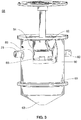
- the solids interceptor 68 is seen in more detail in Figure 3 .
- the inlet 78 and outlet 80 are usually provided at a common level, that will become the static water level as liquid flows through the system.
- the solids collector 68 is primarily made up of a container 69 much like the outer tank 12 of Figure 2 .
- Container 69 preferably is cylindrical with a bottom that slopes downward toward a lowermost central area.
- one of the advantages of the invention is that the container 69 and tank 12 can be manufactured to be identical, thereby reducing manufacturing costs since the one component can be used for either part of the system.
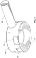
- an intake port 86 of a solids diverter 84 Rigidly affixed to the inlet 78 is an intake port 86 of a solids diverter 84, which is preferably a molded plastic item having a primarily hollow toroidal shape with the pipe-shaped intake 86 protruding from it.
- the pipe shape 86 provides a continuous flow path for the effluent from the inlet 78 into the toroidal shape of the solids diverter 84.
- the solids diverter 84 has a frusto-conically shaped floor 90, sloping from a higher interior radius to a lower outside radius, ending in ports 88 which are positioned lateral from intake 86.
- the solids and their effluent are received in the solids diverter 84 through the intake 86 and turned laterally right and left in the toroidal shaped component.
- An increase in the cross-section area of the flow path of the effluent enables the effluent to slow down its forward linear flow rate, so that the solids slow and can fall out of the toroidal shaped member 84 through the ports 88, descending the sloped floor 90.
- the space above the bottom 63 of the container 69 can collect the falling solids.
- the toroidal shape of the solids diverter 84 provides a vertical open channel which aligns with the port 71 in a drum lid seen in Figure 1 , enabling a suction withdrawal tube to pass through the port 71 through the middle of the toroid, to the bottom 63 of the tank enabling substantially complete removal of solids at clean out time.
- Shapes other than torodial can also be used, such as a branching arrangements of tubes as a Y, a T or other configurations that broaden the cross-section of the flow path to slow this flow and then discharge it into the container 69.
- Other geometries for placement of port 71 for a withdrawal tubes can also be used.
- Outlet 80 can be a port in the side of the container 69 at the height of the solids diverter 84, high enough so that the side ports 88 are submerged.
- An example is seen in the embodiment of Figure 8 . Since that level is at about the height of the static water level in the container 69, any solids that float on the effluent will be passed along with the effluent to the downstream grease interceptor 10.
- the outlet 80 is provided with an invert, such that the intake to the invert is below the static water level, then floating solids will remain in the container 69 and the oil, grease and fat along with the other water can pass through the invert through the outlet 80 to the downstream grease interceptor 10.
- Figure 4 shows the solids diverter in more detail, including the inlet pipe 86, the side ports 88 and sloping wall 90.
- the shape of the solids diverter 84 does not have to be as shown, but should have the features of causing a lateral change of direction of the inflowing effluent with entrained solids, as well as a broadening of the cross-sectional area of the path of the effluent, so as to cause the solids to leave entrainment in the effluent.
- the solids and liquids pass into the container 69 through the inlet 78 and then directly into the solids diverter 84.
- the solids diverter 84 they transfer forward motion to lateral motion and slow down by virtue of increase of the path's cross-sectional area. This allows the solids with a specific gravity greater than water to fall by gravity from the outlet ports 88 down to the bottom 63 of the container 69.
- the solids collect on the bottom 63 and build on the accumulated solids within the container 69. Fat, oil and grease and water in the effluent can pass downstream through outlet 80 to the grease tank 10.
- waste water enters the grease tank 10 via the inlet invert 20.
- the water flows into the diverging space between the upwardly sloped bottom and the downwardly sloped bottom 13. Since the upwardly sloped bottom and the downwardly sloped bottom 13 diverge from the edge of the tank to the center of the tank, as waste water flows into the diverging area, the velocity of the water flow slows, allowing the grease to rise under the influence of gravity, since it is less dense than the water. Any remaining heavy solids sink to the bottom. Lightweight greases float and gather at the upwardly sloped bottom of the inner tank and float through the central hole into the inner tank 14.
- the lightweight greases gather at a location outside of the flow path which is below the upwardly sloped bottom of the inner tank, less grease is allowed to pass back out of the tank via the outlet invert 22.
- the upwardly sloped bottom provides a barrier that sequesters the grease that has become trapped in the inner tank 14 from the flow of water from the inlet 20 to the outlet 22. Thus the grey water current does not entrain the sequestered grease and sweep it out of the grease trap via the outlet invert 22.
- the vertical, internal pipe 17 passes through the upwardly sloped bottom of the inner tank so that the heavy solids collecting in the downwardly sloped bottom 13 may be pumped out. Continued pumping draws water from the tank, and pulls the grease back down to the lower chamber and out through the pipe 17.
- the pipe 17 need not be strictly vertical, but could be slanted or have horizontal elements, as long as it extends to the lower chamber 28 to enable pumping of solids and grease.
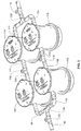
- Figure 5 shows another embodiment of an installation of greater capacity by virtue of the fact of additional solids interceptors and grease interceptors are provided.
- two solids interceptors 100 and 102 are provided along with their associated components on their respective paths. For even greater size volumes, numbers greater than two can be provided. The number of solids interceptors need not match the number of grease interceptors.
- the inlet 90 having a clean out port 92 discharges effluent having both solids and F.O.G. through a flow splitter 94 dividing the flow into the inlets 98 and 96 of solids interceptors 100 and 102 respectively.
- the flow splitter is conventional and in most cases the nature of the flows on lines 96 and 98 are the same or similar, as simple bifurcation of the one effluent flow.
- the solids interceptors 100, 102 the solids are removed as discussed above, and F.O.G.-laden waste water is allowed to discharge through respective discharges 104 and 108. Cleanout ports 110 and 106 are provided so that any clogs can be cleaned out.
- Waste water and FOG are discharged through inlets 114 and 112 into grease interceptors 118 and 116 respectively. These grease interceptors operate as described above.
- the gray water is then allowed to be discharged through discharge pipes 124 and 122, recombined at joint 126 and passed to downstream sewer lines.
- a clean out port 128 can be provided.
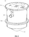
- the grease trap 10 may include an anchor ring 120. If the grease trap 10 is buried in the ground, the anchor in the form of a ring 120 helps engage the surrounding soil and prevent the grease trap 10 from floating to the surface if water surrounds the grease trap 10. Similar rings can be used on the solids interceptor(s). Anchors of other shapes or configurations may be substituted.
- FIG. 7 shows an alternate inner tank configuration 114.
- a "tunnel” (not shown) is formed between the inner tank and the outer tank (where the inlet invert was previously positioned) now creates the inlet passage.
- This "tunnel” looks like the tunnel 21 of Figure 2 but has a larger cross section (by about 50%), so eliminating the invert starts the “slow down” of the flow that much sooner in the process.
- a rectangular cut out 123 is located near the top of an outlet tunnel 121 that is on the outlet side (surrounding the outlet invert). It was found that some quantity of FOG would rise on the outside of the outlet invert and be trapped there. Cutout 123 allows the FOG to transfer into the inner tank and be sequestered. This structure results in two FOG flow paths - the center hole in the bottom of the inner tank and the rectangular hole 123 on the outlet side.
- the center pipe 17 in fig 2 has been shortened so that it does not now go through the hole in the bottom of the inner tank, alleviating any concern that the gap between the pipe and inner tank would be too small and cause a point of clogging with grease or solids that may cause the unit not to function properly.
Landscapes
- Chemical & Material Sciences (AREA)
- Chemical Kinetics & Catalysis (AREA)
- Sewage (AREA)
- Removal Of Floating Material (AREA)
Claims (14)
- Installation de séparateur de graisse pour séparer des matières solides qui sont plus lourdes que l'eau et les F.O.G, les matières grasses, les huiles et la graisse, les déchets des eaux usées comprenant :un intercepteur de matières solides (68) ayant :un récipient (69) ayant un fond (63) ;une entrée (78) dans le récipient pour recevoir les eaux usées au-dessus du fond, etune sortie (80) du récipient pour libérer les eaux usées au-dessus du fond, pour permettre aux matières solides de se séparer, par gravitation, vers le fond alors que les eaux usées, au moins partiellement appauvries en matières solides plus lourdes que l'eau, sont déchargées du récipient par la sortie ; etun réservoir (12) ayant :un inverseur d'entrée (20) dans le réservoir raccordé à la sortie (80) du récipient (69) pour recevoir les eaux usées entrantes au moins partiellement appauvries en matières solides dans le réservoir,un inverseur de sortie (22) pour retirer l'eau du réservoir, etun couvercle (16) recouvrant le réservoir,caractérisée en ce que le réservoir (12) a :un fond (13) formé vers le bas,un diviseur (90) incliné vers le haut divisant le réservoir en une chambre supérieure et en une chambre inférieure, le diviseur ayant un trou pour permettre l'introduction des déchets dans la chambre supérieure, etun tuyau s'étendant vers la chambre inférieure pour permettre l'aspiration des déchets solides hors de la chambre inférieure.
- Installation de séparateur de graisse selon la revendication 1, dans laquelle le récipient (69) est du plastique rotomoulé.
- Installation de séparateur de graisse selon la revendication 1 ou la revendication 2, dans laquelle le réservoir (12) et le récipient (69) ont la même taille et la même forme.
- Installation de séparateur de graisse selon l'une quelconque des revendications précédentes, dans laquelle le diviseur incliné vers le haut est formé comme un fond d'un réservoir interne (114) et le réservoir interne est positionné dans un réservoir externe, le réservoir interne ayant un tunnel d'entrée, et un déflecteur en forme d'ailette (120) sur le diviseur à proximité du tunnel d'entrée pour forcer l'écoulement entrant vers la périphérie du réservoir externe.
- Installation de séparateur de graisse selon l'une quelconque des revendications précédentes, dans laquelle le diviseur incliné vers le haut est formé comme un fond d'un réservoir interne (14) et le réservoir interne a un tunnel de sortie entourant l'inverseur de sortie (22) et une découpe positionnée à proximité de la partie supérieure du tunnel de sortie pour permettre l'introduction des F.O.G dans le tunnel de sortie pour le transfert dans le réservoir interne et être séquestrés.
- Installation de séparateur de graisse selon la revendication 1, dans laquelle le récipient (69) de l'intercepteur de matières solides (68) a une paroi latérale cylindrique et un fond incliné vers le bas (63), l'entrée (78) et la sortie (80) sont raccordées à la paroi latérale au-dessus du fond incliné ; et
un dérouteur de matières solides (84) est raccordé à l'entrée et positionné à l'intérieur du récipient et configuré avec une trajectoire d'écoulement pour les eaux usées qui augmente en surface transversale afin de ralentir les eaux usées entrant dans le récipient d'une vitesse supérieure à une vitesse inférieure et ainsi réduire l'entraînement des matières solides qui sont plus lourdes que l'eau dans les eaux usées ralenties pour permettre aux matières solides de précipiter au fond de l'intercepteur de matières solides. - Installation de séparateur de graisse selon la revendication 6, dans lequel le dérouteur de matières solides (84) comprend un logement fournissant des trajectoires transversales pour les eaux usées entrantes et des ouvertures (88) latérales de l'entrée (78) pour dévier et retarder les eaux usées entrantes.
- Installation de séparateur de graisse selon la revendication 7, dans laquelle la trajectoire comprend un plancher (90) qui s'incline vers le bas vers les ouvertures.
- Installation de séparateur de graisse selon la revendication 7, dans laquelle les ouvertures (88) sont transversales par rapport à une trajectoire de l'entrée à la sortie à l'intérieur du réservoir.
- Installation de séparateur de graisse selon la revendication 6, dans laquelle le dérouteur de matières solides (84) comprend un logement fournissant une trajectoire annulaire pour les eaux usées entrantes et des ouvertures (88) latérales de l'entrée (78) pour dévier et retarder les eaux usées entrantes, dans laquelle les ouvertures sont transversales par rapport à une trajectoire de l'entrée à la sortie à l'intérieur du réservoir, et dans laquelle la trajectoire annulaire comprend un plancher (90) qui s'incline vers le bas depuis l'intérieur de l'espace annulaire jusqu'aux ouvertures au niveau d'une périphérie de l'espace annulaire.
- Procédé pour installer une installation de séparateur de graisse selon l'une quelconque des revendications précédentes pour séparer les déchets des eaux usées, le procédé comprenant les étapes suivantes :installer le récipient (69) ayant le fond (63) et l'entrée (78) pour recevoir les eaux usées au-dessus du fond et la sortie (80) au-dessus du fond ;raccorder l'entrée à une source d'effluent comprenant des matières solides, des eaux usées et des F.O.G ;en aval de la sortie du récipient, installer le réservoir (12) ayant un fond incliné vers le bas (13) et raccorder la sortie du récipient à un inverseur d'entrée (20) dans le réservoir ;raccorder un inverseur de sortie (22) du réservoir à une ligne de décharge d'eaux d'égout ; etpositionner un couvercle (16) recouvrant le réservoir.
- Procédé selon la revendication 11, lorsqu'elle dépend des revendications 6 à 10, comprenant les étapes suivantes: raccorder un dérouteur de matières solides (84) à l'entrée et positionner le dérouteur de matières solides à l'intérieur du récipient, au-dessus d'un niveau de collecte de matières solides et au-dessous d'un niveau de collecte de F.O.G.
- Procédé selon les revendications 11 ou 12, comprenant l'étape préliminaire suivante : mouler le récipient (69) et le réservoir (12) dans le même moule de sorte que le réservoir et le récipient ont la même taille et la même forme.
- Procédé selon la revendication 11 ou la revendication 12, comprenant l'étape préliminaire suivante : réaliser le récipient (69), la réalisation du récipient comprenant les étapes suivantes :mouler le récipient ayant une paroi latérale cylindrique et le fond incliné vers le bas ;installer l'entrée (78) et la sortie (80) sur les segments opposés de la paroi latérales cylindrique ; etinstaller un déflecteur sur l'entrée, configuré pour ralentir les eaux usées entrant dans le récipient d'une vitesse supérieure à une vitesse inférieure et réduire ainsi l'entraînement des matières solides qui sont plus lourdes que l'eau dans les eaux usées ralenties pour permettre aux matières solides de précipiter au fond de l'intercepteur de matières solides.
Applications Claiming Priority (2)
| Application Number | Priority Date | Filing Date | Title |
|---|---|---|---|
| US11/929,104 US7641805B2 (en) | 2007-10-30 | 2007-10-30 | Passive grease trap with pre-stage for solids separation |
| PCT/US2008/080195 WO2009058581A1 (fr) | 2007-10-30 | 2008-10-16 | Séparateur de graisse passif avec pré-étage pour une séparation de matières solides |
Publications (3)
| Publication Number | Publication Date |
|---|---|
| EP2219800A1 EP2219800A1 (fr) | 2010-08-25 |
| EP2219800A4 EP2219800A4 (fr) | 2012-04-04 |
| EP2219800B1 true EP2219800B1 (fr) | 2018-06-27 |
Family
ID=40581463
Family Applications (1)
| Application Number | Title | Priority Date | Filing Date |
|---|---|---|---|
| EP08845252.9A Active EP2219800B1 (fr) | 2007-10-30 | 2008-10-16 | Séparateur de graisse passif avec pré-étage pour une séparation de matières solides et sa méthode d'installation |
Country Status (8)
| Country | Link |
|---|---|
| US (1) | US7641805B2 (fr) |
| EP (1) | EP2219800B1 (fr) |
| AU (1) | AU2008319070B2 (fr) |
| BR (1) | BRPI0818735A2 (fr) |
| CA (1) | CA2703567C (fr) |
| MX (1) | MX2010004769A (fr) |
| NZ (1) | NZ584944A (fr) |
| WO (1) | WO2009058581A1 (fr) |
Families Citing this family (16)
| Publication number | Priority date | Publication date | Assignee | Title |
|---|---|---|---|---|
| US20110100897A1 (en) * | 2009-10-30 | 2011-05-05 | Wesley Boerm | System and method for liquid purification |
| CA2778016C (fr) | 2012-05-23 | 2018-06-19 | Canplas Industries Ltd. | Dispositif de confinement de solides a utiliser dans un separateur de graisse hydromecanique ou en association avec celui-ci |
| AU2012101773B4 (en) * | 2012-12-05 | 2013-09-19 | Sic Viresco Pty Ltd | Method and system for treatment of waste |
| US9932732B1 (en) * | 2013-05-20 | 2018-04-03 | Thermaco, Inc. | Passive grease trap with lift system |
| US9528258B1 (en) | 2014-08-21 | 2016-12-27 | Thermaco, Inc. | Manhole ring support for unified concrete pours around grease interceptor |
| CA2866911C (fr) | 2014-10-09 | 2021-04-27 | Canplas Industries Ltd. | Un couvercle de puits de production destine a un intercepteur de graisse en ligne |
| WO2016094299A1 (fr) | 2014-12-08 | 2016-06-16 | Contech Engineered Solutions LLC | Séparateur hydrodynamique |
| US9932247B1 (en) * | 2015-03-27 | 2018-04-03 | Thermaco, Inc. | Passive grease trap using separator technology |
| CA2903838C (fr) | 2015-09-10 | 2022-08-23 | Canplas Industries Ltd. | Recipient de separation des eaux usees |
| US9889392B2 (en) | 2016-06-03 | 2018-02-13 | Teik Sim Quah | Grease separator |
| US10150063B2 (en) | 2016-12-29 | 2018-12-11 | Contech Engineered Solutions LLC | Hydrodynamic separator |
| US11578480B2 (en) | 2017-01-30 | 2023-02-14 | Oldcastle Precast Inc. | Grease interceptor and method of use thereof |
| MX392160B (es) | 2018-10-08 | 2025-03-04 | Thermaco Incorporated | Trampa de grasa pasiva con doble deflector |
| WO2020160357A1 (fr) | 2019-02-01 | 2020-08-06 | Thermaco, Incorporated | Piège à graisse rotomoulé multicouche |
| US11267726B1 (en) | 2020-03-09 | 2022-03-08 | Thermaco, Incorporated | Grease trap with safety barrier |
| US10941557B1 (en) | 2020-04-14 | 2021-03-09 | S & M Precast, Inc. | Water quality unit for flow-through manhole |
Family Cites Families (55)
| Publication number | Priority date | Publication date | Assignee | Title |
|---|---|---|---|---|
| US978889A (en) | 1910-02-19 | 1910-12-20 | Karl Imhoff | Treating sewage. |
| US1200951A (en) | 1916-01-19 | 1916-10-10 | Kelly Separator Company | Separator. |
| US2226968A (en) | 1937-12-06 | 1940-12-31 | Clerici Carlo | Basin for clarifying and cleansing dirty and drain waters |
| US2213458A (en) | 1938-09-02 | 1940-09-03 | J W Swanson | Septic tank |
| US2338971A (en) * | 1942-04-27 | 1944-01-11 | Illinois Iron & Bolt Company | Grease separator |
| US3224593A (en) | 1961-05-23 | 1965-12-21 | Nebolsine Ross | Apparatus for separation of oil from aqueous mixtures |
| US3662918A (en) * | 1970-08-24 | 1972-05-16 | David D Crawford | Reinforced septic tank |
| US4038186A (en) * | 1975-10-14 | 1977-07-26 | Texaco Inc. | Carbon decanter |
| DE8001771U1 (de) | 1979-03-26 | 1984-02-09 | Novex Találmányfejlesztö és Ertékesítö Külkereskedelmi Rt., Budapest | Vorrichtung zum behandeln von fluessigkeiten |
| HU181642B (en) | 1979-12-12 | 1983-10-28 | Arvizvedelmi Es Belvizvedelmi | Method and device for removing floating liquid contaminations particularly oil ones |
| FR2480617B1 (fr) | 1980-04-21 | 1986-01-17 | Bardet Sa Ets Andre | Appareil et installation de separation de liquides non miscibles de densites differentes |
| NZ197894A (en) | 1980-08-11 | 1985-07-12 | Hydro Int Ltd | Vortex separator for sewage treatment;conical flow modifier in solids outlet |
| US4385986A (en) | 1981-04-08 | 1983-05-31 | Nelson Industries, Inc. | Gravity separator for separating liquids |
| US4554366A (en) * | 1982-09-13 | 1985-11-19 | Shell Oil Company | Certain substituted, 7-oxabicyclo[2.2.1]heptan-2-ols and -2-ones as intermediates |
| US4554074A (en) | 1984-07-20 | 1985-11-19 | Broughton Amos W | Separator for immiscible fluid mixture |
| US5861098A (en) | 1996-11-27 | 1999-01-19 | Mdk Enterprises, Inc. | Apparatus and method for removing grease from drain water in restaurant operations |
| US4938878A (en) | 1988-02-16 | 1990-07-03 | Halltech Inc. | Immiscible separating device |
| US4832846A (en) * | 1988-08-04 | 1989-05-23 | Gavin Norman W | Septic tank baffle |
| US5021153A (en) | 1989-11-20 | 1991-06-04 | G-H Systems, Inc. | Combined apparatus for removing grit and grease from sewage |
| US4985148A (en) | 1990-02-08 | 1991-01-15 | Fibresep Ltd. | Improved separator tank construction |
| US5178754A (en) | 1991-05-20 | 1993-01-12 | Thermaco, Inc. | Grease and solids removal system |
| US5225085A (en) | 1991-11-07 | 1993-07-06 | Napier Laksir P | Apparatus and process for the separation and reclamation of selected components in grease trap waste |
| US5204000A (en) * | 1992-01-31 | 1993-04-20 | Zcl Mfg Canada Inc. | Tank for separating water and hydrocarbon fuels from contaminated water |
| HU209763B (en) | 1992-03-18 | 1994-10-28 | Szereday | Apparatus for separating first liquid contamination floating on fluid e.g. oil and the fluid e.g. water |
| US5405538A (en) | 1994-01-07 | 1995-04-11 | Clearline Systems, Inc. | Immiscible liquids separator |
| US5453197A (en) * | 1994-02-01 | 1995-09-26 | Strefling; Martin P. | Fuel-water contaminant separator |
| US5453187A (en) | 1994-02-15 | 1995-09-26 | Plumb; Arnold D. | Food, oil and grease accumulation apparatus and method |
| US5543064A (en) * | 1994-09-07 | 1996-08-06 | Clearline Systems, Inc. | Sewage lift station |
| US5505860A (en) | 1994-10-24 | 1996-04-09 | Sager; Robert J. | Grease and oil trap |
| US5565101A (en) | 1995-02-15 | 1996-10-15 | Spokane Industries, Inc. | Oil and water separator |
| US5746911A (en) | 1997-01-13 | 1998-05-05 | Pank; Thomas E. | Apparatus for separating a light from a heavy fluid |
| CA2175277C (fr) | 1996-04-29 | 1999-03-23 | Joseph Gordon Monteith | Reservoir separateur ameliore |
| US5730872A (en) | 1996-05-10 | 1998-03-24 | Rhodes; Laurence Mark | Apparatus for separating a mixture of liquids |
| US5714069A (en) | 1996-09-25 | 1998-02-03 | Sager; Robert | Apparatus for removing grease from waste water |
| US5718824A (en) | 1996-10-01 | 1998-02-17 | Crane Co. | Collector hood for sedimentation tank |
| US5849181A (en) | 1997-06-02 | 1998-12-15 | Stormceptor Corporation | Catch basin |
| US6120684A (en) * | 1998-01-06 | 2000-09-19 | Tec-Kon Enterprises, Llc | Stormwater treatment system |
| US5993646A (en) | 1998-05-01 | 1999-11-30 | Norwood Industries, Inc. | Grease trap |
| SE512069C2 (sv) | 1998-07-20 | 2000-01-24 | Bert Gustafsson | Anordning benämnd kammarfördelnings-insats, avsedd att monteras i fogen mellan två betongrör för uppdelning av rörkroppen i flera separata kammare |
| US6238572B1 (en) | 1998-07-21 | 2001-05-29 | Clearline Systems, Inc. | Separation tank module for kitchen effluent |
| US20010025811A1 (en) | 1998-07-21 | 2001-10-04 | Batten William C. | Separation tank module for kitchen effluent |
| US6139730A (en) * | 1998-12-28 | 2000-10-31 | Jay R. Smith Manufacturing Co. | Multichamber gravity operated oil-water separator |
| US6068765A (en) | 1999-03-26 | 2000-05-30 | Stormceptor Corporation | Separator tank |
| GB9908634D0 (en) * | 1999-04-15 | 1999-06-09 | Hydro Int Ltd | Hydrodynamic vortex separator |
| US6328890B1 (en) * | 1999-08-05 | 2001-12-11 | Osborne Industries, Inc. | Septic waste treatment system |
| US6517715B1 (en) * | 1999-11-12 | 2003-02-11 | Thermaco, Inc. | Readily serviceable separator unit with a focusing plate |
| US6619317B2 (en) * | 2000-04-28 | 2003-09-16 | Schroeder Industries L.L.C. | Rotomolded hydraulic reservoir with integral filter bowl |
| US6413435B1 (en) | 2000-09-22 | 2002-07-02 | Thermaco, Inc. | Separator unit capable of less-dense solids and/or buoyant solids removal |
| EP1232779A1 (fr) * | 2001-02-15 | 2002-08-21 | Evac International Oy | Séparateur |
| US6800195B1 (en) * | 2002-06-04 | 2004-10-05 | Thermaco, Inc. | Low cost grease removal system |
| WO2004087282A2 (fr) * | 2003-03-25 | 2004-10-14 | Zurn Industries, Inc. | Systeme de degraissage |
| US7361282B2 (en) * | 2003-07-21 | 2008-04-22 | Smullin Corporation | Separator of floating components |
| US6951619B2 (en) * | 2003-08-22 | 2005-10-04 | Graham Bryant | Apparatus for trapping floating and non-floating particulate matter |
| US6849176B1 (en) * | 2003-09-04 | 2005-02-01 | Thermaco, Inc. | Grease separator for kitchen sinks and other applications |
| US7367459B2 (en) | 2006-04-27 | 2008-05-06 | Thermaco, Inc. | Passive grease trap using separator technology |
-
2007
- 2007-10-30 US US11/929,104 patent/US7641805B2/en active Active
-
2008
- 2008-10-16 AU AU2008319070A patent/AU2008319070B2/en active Active
- 2008-10-16 MX MX2010004769A patent/MX2010004769A/es active IP Right Grant
- 2008-10-16 NZ NZ584944A patent/NZ584944A/xx unknown
- 2008-10-16 EP EP08845252.9A patent/EP2219800B1/fr active Active
- 2008-10-16 BR BRPI0818735A patent/BRPI0818735A2/pt not_active Application Discontinuation
- 2008-10-16 CA CA2703567A patent/CA2703567C/fr active Active
- 2008-10-16 WO PCT/US2008/080195 patent/WO2009058581A1/fr not_active Ceased
Non-Patent Citations (1)
| Title |
|---|
| None * |
Also Published As
| Publication number | Publication date |
|---|---|
| EP2219800A4 (fr) | 2012-04-04 |
| EP2219800A1 (fr) | 2010-08-25 |
| AU2008319070A1 (en) | 2009-05-07 |
| BRPI0818735A2 (pt) | 2018-08-28 |
| NZ584944A (en) | 2012-11-30 |
| US20090107910A1 (en) | 2009-04-30 |
| CA2703567A1 (fr) | 2009-05-07 |
| US7641805B2 (en) | 2010-01-05 |
| WO2009058581A1 (fr) | 2009-05-07 |
| CA2703567C (fr) | 2015-10-13 |
| MX2010004769A (es) | 2010-09-30 |
| AU2008319070B2 (en) | 2014-05-01 |
Similar Documents
| Publication | Publication Date | Title |
|---|---|---|
| EP2219800B1 (fr) | Séparateur de graisse passif avec pré-étage pour une séparation de matières solides et sa méthode d'installation | |
| EP2010301B1 (fr) | Intercepteur de graisse passif faisant appel à la technologie des séparateurs, ses methodes de fabrication et d'utilisation | |
| EP0711879B1 (fr) | Reservoir d'interception | |
| US6547962B2 (en) | Stormwater treatment system | |
| US10526216B1 (en) | Passive grease trap using separator technology | |
| CA2697287A1 (fr) | Systeme de traitement et de derivation d'eau | |
| US11040895B2 (en) | Passive grease trap with double baffle | |
| JP2002521171A (ja) | 液体流入物から不混和性液体を分離するための装置と方法 | |
| US9932732B1 (en) | Passive grease trap with lift system | |
| US10058798B2 (en) | Outlet well cover for an in-line grease interceptor | |
| HK1129337B (en) | Passive grease trap using separator technology | |
| EP1510627A1 (fr) | Séparateur de graisse | |
| IE20040570A1 (en) | A waste treatment system |
Legal Events
| Date | Code | Title | Description |
|---|---|---|---|
| PUAI | Public reference made under article 153(3) epc to a published international application that has entered the european phase |
Free format text: ORIGINAL CODE: 0009012 |
|
| 17P | Request for examination filed |
Effective date: 20100505 |
|
| AK | Designated contracting states |
Kind code of ref document: A1 Designated state(s): AT BE BG CH CY CZ DE DK EE ES FI FR GB GR HR HU IE IS IT LI LT LU LV MC MT NL NO PL PT RO SE SI SK TR |
|
| AX | Request for extension of the european patent |
Extension state: AL BA MK RS |
|
| DAX | Request for extension of the european patent (deleted) | ||
| A4 | Supplementary search report drawn up and despatched |
Effective date: 20120306 |
|
| RIC1 | Information provided on ipc code assigned before grant |
Ipc: C02F 1/40 20060101ALI20120227BHEP Ipc: B21D 35/00 20060101AFI20120227BHEP |
|
| 17Q | First examination report despatched |
Effective date: 20130909 |
|
| RIC1 | Information provided on ipc code assigned before grant |
Ipc: B01D 21/24 20060101ALI20171122BHEP Ipc: B21D 35/00 20060101AFI20171122BHEP Ipc: C02F 1/40 20060101ALI20171122BHEP Ipc: B01D 21/00 20060101ALI20171122BHEP |
|
| GRAP | Despatch of communication of intention to grant a patent |
Free format text: ORIGINAL CODE: EPIDOSNIGR1 |
|
| INTG | Intention to grant announced |
Effective date: 20180117 |
|
| GRAS | Grant fee paid |
Free format text: ORIGINAL CODE: EPIDOSNIGR3 |
|
| GRAA | (expected) grant |
Free format text: ORIGINAL CODE: 0009210 |
|
| AK | Designated contracting states |
Kind code of ref document: B1 Designated state(s): AT BE BG CH CY CZ DE DK EE ES FI FR GB GR HR HU IE IS IT LI LT LU LV MC MT NL NO PL PT RO SE SI SK TR |
|
| REG | Reference to a national code |
Ref country code: GB Ref legal event code: FG4D |
|
| REG | Reference to a national code |
Ref country code: AT Ref legal event code: REF Ref document number: 1011857 Country of ref document: AT Kind code of ref document: T Effective date: 20180715 |
|
| REG | Reference to a national code |
Ref country code: IE Ref legal event code: FG4D |
|
| REG | Reference to a national code |
Ref country code: DE Ref legal event code: R096 Ref document number: 602008055787 Country of ref document: DE |
|
| REG | Reference to a national code |
Ref country code: FR Ref legal event code: PLFP Year of fee payment: 11 |
|
| PG25 | Lapsed in a contracting state [announced via postgrant information from national office to epo] |
Ref country code: SE Free format text: LAPSE BECAUSE OF FAILURE TO SUBMIT A TRANSLATION OF THE DESCRIPTION OR TO PAY THE FEE WITHIN THE PRESCRIBED TIME-LIMIT Effective date: 20180627 Ref country code: NO Free format text: LAPSE BECAUSE OF FAILURE TO SUBMIT A TRANSLATION OF THE DESCRIPTION OR TO PAY THE FEE WITHIN THE PRESCRIBED TIME-LIMIT Effective date: 20180927 Ref country code: FI Free format text: LAPSE BECAUSE OF FAILURE TO SUBMIT A TRANSLATION OF THE DESCRIPTION OR TO PAY THE FEE WITHIN THE PRESCRIBED TIME-LIMIT Effective date: 20180627 Ref country code: BG Free format text: LAPSE BECAUSE OF FAILURE TO SUBMIT A TRANSLATION OF THE DESCRIPTION OR TO PAY THE FEE WITHIN THE PRESCRIBED TIME-LIMIT Effective date: 20180927 Ref country code: LT Free format text: LAPSE BECAUSE OF FAILURE TO SUBMIT A TRANSLATION OF THE DESCRIPTION OR TO PAY THE FEE WITHIN THE PRESCRIBED TIME-LIMIT Effective date: 20180627 |
|
| REG | Reference to a national code |
Ref country code: NL Ref legal event code: MP Effective date: 20180627 |
|
| REG | Reference to a national code |
Ref country code: LT Ref legal event code: MG4D |
|
| PG25 | Lapsed in a contracting state [announced via postgrant information from national office to epo] |
Ref country code: GR Free format text: LAPSE BECAUSE OF FAILURE TO SUBMIT A TRANSLATION OF THE DESCRIPTION OR TO PAY THE FEE WITHIN THE PRESCRIBED TIME-LIMIT Effective date: 20180928 Ref country code: HR Free format text: LAPSE BECAUSE OF FAILURE TO SUBMIT A TRANSLATION OF THE DESCRIPTION OR TO PAY THE FEE WITHIN THE PRESCRIBED TIME-LIMIT Effective date: 20180627 Ref country code: LV Free format text: LAPSE BECAUSE OF FAILURE TO SUBMIT A TRANSLATION OF THE DESCRIPTION OR TO PAY THE FEE WITHIN THE PRESCRIBED TIME-LIMIT Effective date: 20180627 |
|
| REG | Reference to a national code |
Ref country code: AT Ref legal event code: MK05 Ref document number: 1011857 Country of ref document: AT Kind code of ref document: T Effective date: 20180627 |
|
| PG25 | Lapsed in a contracting state [announced via postgrant information from national office to epo] |
Ref country code: NL Free format text: LAPSE BECAUSE OF FAILURE TO SUBMIT A TRANSLATION OF THE DESCRIPTION OR TO PAY THE FEE WITHIN THE PRESCRIBED TIME-LIMIT Effective date: 20180627 |
|
| PG25 | Lapsed in a contracting state [announced via postgrant information from national office to epo] |
Ref country code: RO Free format text: LAPSE BECAUSE OF FAILURE TO SUBMIT A TRANSLATION OF THE DESCRIPTION OR TO PAY THE FEE WITHIN THE PRESCRIBED TIME-LIMIT Effective date: 20180627 Ref country code: CZ Free format text: LAPSE BECAUSE OF FAILURE TO SUBMIT A TRANSLATION OF THE DESCRIPTION OR TO PAY THE FEE WITHIN THE PRESCRIBED TIME-LIMIT Effective date: 20180627 Ref country code: SK Free format text: LAPSE BECAUSE OF FAILURE TO SUBMIT A TRANSLATION OF THE DESCRIPTION OR TO PAY THE FEE WITHIN THE PRESCRIBED TIME-LIMIT Effective date: 20180627 Ref country code: EE Free format text: LAPSE BECAUSE OF FAILURE TO SUBMIT A TRANSLATION OF THE DESCRIPTION OR TO PAY THE FEE WITHIN THE PRESCRIBED TIME-LIMIT Effective date: 20180627 Ref country code: IS Free format text: LAPSE BECAUSE OF FAILURE TO SUBMIT A TRANSLATION OF THE DESCRIPTION OR TO PAY THE FEE WITHIN THE PRESCRIBED TIME-LIMIT Effective date: 20181027 Ref country code: AT Free format text: LAPSE BECAUSE OF FAILURE TO SUBMIT A TRANSLATION OF THE DESCRIPTION OR TO PAY THE FEE WITHIN THE PRESCRIBED TIME-LIMIT Effective date: 20180627 Ref country code: PL Free format text: LAPSE BECAUSE OF FAILURE TO SUBMIT A TRANSLATION OF THE DESCRIPTION OR TO PAY THE FEE WITHIN THE PRESCRIBED TIME-LIMIT Effective date: 20180627 |
|
| PG25 | Lapsed in a contracting state [announced via postgrant information from national office to epo] |
Ref country code: IT Free format text: LAPSE BECAUSE OF FAILURE TO SUBMIT A TRANSLATION OF THE DESCRIPTION OR TO PAY THE FEE WITHIN THE PRESCRIBED TIME-LIMIT Effective date: 20180627 Ref country code: ES Free format text: LAPSE BECAUSE OF FAILURE TO SUBMIT A TRANSLATION OF THE DESCRIPTION OR TO PAY THE FEE WITHIN THE PRESCRIBED TIME-LIMIT Effective date: 20180627 |
|
| REG | Reference to a national code |
Ref country code: DE Ref legal event code: R097 Ref document number: 602008055787 Country of ref document: DE |
|
| PLBE | No opposition filed within time limit |
Free format text: ORIGINAL CODE: 0009261 |
|
| STAA | Information on the status of an ep patent application or granted ep patent |
Free format text: STATUS: NO OPPOSITION FILED WITHIN TIME LIMIT |
|
| PG25 | Lapsed in a contracting state [announced via postgrant information from national office to epo] |
Ref country code: DK Free format text: LAPSE BECAUSE OF FAILURE TO SUBMIT A TRANSLATION OF THE DESCRIPTION OR TO PAY THE FEE WITHIN THE PRESCRIBED TIME-LIMIT Effective date: 20180627 |
|
| REG | Reference to a national code |
Ref country code: CH Ref legal event code: PL |
|
| 26N | No opposition filed |
Effective date: 20190328 |
|
| REG | Reference to a national code |
Ref country code: BE Ref legal event code: MM Effective date: 20181031 |
|
| PG25 | Lapsed in a contracting state [announced via postgrant information from national office to epo] |
Ref country code: MC Free format text: LAPSE BECAUSE OF FAILURE TO SUBMIT A TRANSLATION OF THE DESCRIPTION OR TO PAY THE FEE WITHIN THE PRESCRIBED TIME-LIMIT Effective date: 20180627 Ref country code: LU Free format text: LAPSE BECAUSE OF NON-PAYMENT OF DUE FEES Effective date: 20181016 |
|
| PG25 | Lapsed in a contracting state [announced via postgrant information from national office to epo] |
Ref country code: SI Free format text: LAPSE BECAUSE OF FAILURE TO SUBMIT A TRANSLATION OF THE DESCRIPTION OR TO PAY THE FEE WITHIN THE PRESCRIBED TIME-LIMIT Effective date: 20180627 Ref country code: CH Free format text: LAPSE BECAUSE OF NON-PAYMENT OF DUE FEES Effective date: 20181031 Ref country code: LI Free format text: LAPSE BECAUSE OF NON-PAYMENT OF DUE FEES Effective date: 20181031 Ref country code: BE Free format text: LAPSE BECAUSE OF NON-PAYMENT OF DUE FEES Effective date: 20181031 |
|
| PG25 | Lapsed in a contracting state [announced via postgrant information from national office to epo] |
Ref country code: MT Free format text: LAPSE BECAUSE OF NON-PAYMENT OF DUE FEES Effective date: 20181016 |
|
| PG25 | Lapsed in a contracting state [announced via postgrant information from national office to epo] |
Ref country code: TR Free format text: LAPSE BECAUSE OF FAILURE TO SUBMIT A TRANSLATION OF THE DESCRIPTION OR TO PAY THE FEE WITHIN THE PRESCRIBED TIME-LIMIT Effective date: 20180627 |
|
| PG25 | Lapsed in a contracting state [announced via postgrant information from national office to epo] |
Ref country code: PT Free format text: LAPSE BECAUSE OF FAILURE TO SUBMIT A TRANSLATION OF THE DESCRIPTION OR TO PAY THE FEE WITHIN THE PRESCRIBED TIME-LIMIT Effective date: 20180627 |
|
| PG25 | Lapsed in a contracting state [announced via postgrant information from national office to epo] |
Ref country code: HU Free format text: LAPSE BECAUSE OF FAILURE TO SUBMIT A TRANSLATION OF THE DESCRIPTION OR TO PAY THE FEE WITHIN THE PRESCRIBED TIME-LIMIT; INVALID AB INITIO Effective date: 20081016 Ref country code: CY Free format text: LAPSE BECAUSE OF FAILURE TO SUBMIT A TRANSLATION OF THE DESCRIPTION OR TO PAY THE FEE WITHIN THE PRESCRIBED TIME-LIMIT Effective date: 20180627 |
|
| PGFP | Annual fee paid to national office [announced via postgrant information from national office to epo] |
Ref country code: DE Payment date: 20251020 Year of fee payment: 18 |
|
| PGFP | Annual fee paid to national office [announced via postgrant information from national office to epo] |
Ref country code: GB Payment date: 20251007 Year of fee payment: 18 |
|
| PGFP | Annual fee paid to national office [announced via postgrant information from national office to epo] |
Ref country code: FR Payment date: 20251029 Year of fee payment: 18 |
|
| PGFP | Annual fee paid to national office [announced via postgrant information from national office to epo] |
Ref country code: IE Payment date: 20251021 Year of fee payment: 18 |
|
| REG | Reference to a national code |
Ref country code: DE Ref legal event code: R082 Ref document number: 602008055787 Country of ref document: DE Representative=s name: DR. RIEBLING & PARTNER PATENTANWAELTE MBB, DE |