EP2221016A2 - Tuyau en deux pièces pour appareil de coagulation aspirant - Google Patents
Tuyau en deux pièces pour appareil de coagulation aspirant Download PDFInfo
- Publication number
- EP2221016A2 EP2221016A2 EP10153960A EP10153960A EP2221016A2 EP 2221016 A2 EP2221016 A2 EP 2221016A2 EP 10153960 A EP10153960 A EP 10153960A EP 10153960 A EP10153960 A EP 10153960A EP 2221016 A2 EP2221016 A2 EP 2221016A2
- Authority
- EP
- European Patent Office
- Prior art keywords
- tube
- shaft
- electrode
- electrosurgical
- distal end
- Prior art date
- Legal status (The legal status is an assumption and is not a legal conclusion. Google has not performed a legal analysis and makes no representation as to the accuracy of the status listed.)
- Withdrawn
Links
- 239000004020 conductor Substances 0.000 claims description 28
- 238000004891 communication Methods 0.000 claims description 15
- 239000000463 material Substances 0.000 claims description 11
- 239000012530 fluid Substances 0.000 claims description 10
- 229910052782 aluminium Inorganic materials 0.000 claims description 8
- XAGFODPZIPBFFR-UHFFFAOYSA-N aluminium Chemical compound [Al] XAGFODPZIPBFFR-UHFFFAOYSA-N 0.000 claims description 8
- 239000004800 polyvinyl chloride Substances 0.000 claims description 8
- 239000010935 stainless steel Substances 0.000 claims description 8
- 229910001220 stainless steel Inorganic materials 0.000 claims description 8
- 229920000915 polyvinyl chloride Polymers 0.000 claims description 7
- 229920001940 conductive polymer Polymers 0.000 claims description 5
- 229910000838 Al alloy Inorganic materials 0.000 claims description 2
- 229910000831 Steel Inorganic materials 0.000 claims description 2
- 239000010959 steel Substances 0.000 claims description 2
- 229920001169 thermoplastic Polymers 0.000 claims description 2
- 229920002635 polyurethane Polymers 0.000 claims 1
- 239000004814 polyurethane Substances 0.000 claims 1
- 210000001519 tissue Anatomy 0.000 description 16
- 238000001356 surgical procedure Methods 0.000 description 14
- 238000010168 coupling process Methods 0.000 description 6
- 239000003989 dielectric material Substances 0.000 description 6
- 239000000853 adhesive Substances 0.000 description 4
- 230000001070 adhesive effect Effects 0.000 description 4
- 229920000642 polymer Polymers 0.000 description 4
- 238000003466 welding Methods 0.000 description 4
- 230000000740 bleeding effect Effects 0.000 description 3
- 238000002788 crimping Methods 0.000 description 3
- 238000005476 soldering Methods 0.000 description 3
- 229910045601 alloy Inorganic materials 0.000 description 2
- 239000000956 alloy Substances 0.000 description 2
- 210000003484 anatomy Anatomy 0.000 description 2
- 239000011248 coating agent Substances 0.000 description 2
- 238000000576 coating method Methods 0.000 description 2
- 238000010292 electrical insulation Methods 0.000 description 2
- 230000009975 flexible effect Effects 0.000 description 2
- 239000007769 metal material Substances 0.000 description 2
- 238000000034 method Methods 0.000 description 2
- -1 without limitation Substances 0.000 description 2
- 229910000851 Alloy steel Inorganic materials 0.000 description 1
- 206010015150 Erythema Diseases 0.000 description 1
- 206010030113 Oedema Diseases 0.000 description 1
- 230000004913 activation Effects 0.000 description 1
- 239000008280 blood Substances 0.000 description 1
- 210000004369 blood Anatomy 0.000 description 1
- 210000004204 blood vessel Anatomy 0.000 description 1
- 230000015271 coagulation Effects 0.000 description 1
- 238000005345 coagulation Methods 0.000 description 1
- 238000010276 construction Methods 0.000 description 1
- 230000008878 coupling Effects 0.000 description 1
- 238000005859 coupling reaction Methods 0.000 description 1
- 230000009849 deactivation Effects 0.000 description 1
- 238000002224 dissection Methods 0.000 description 1
- 230000000694 effects Effects 0.000 description 1
- 231100000321 erythema Toxicity 0.000 description 1
- 230000023597 hemostasis Effects 0.000 description 1
- 239000011810 insulating material Substances 0.000 description 1
- 238000009413 insulation Methods 0.000 description 1
- 239000012212 insulator Substances 0.000 description 1
- 239000012811 non-conductive material Substances 0.000 description 1
- 210000002396 uvula Anatomy 0.000 description 1
Images




Classifications
-
- A—HUMAN NECESSITIES
- A61—MEDICAL OR VETERINARY SCIENCE; HYGIENE
- A61B—DIAGNOSIS; SURGERY; IDENTIFICATION
- A61B18/00—Surgical instruments, devices or methods for transferring non-mechanical forms of energy to or from the body
- A61B18/04—Surgical instruments, devices or methods for transferring non-mechanical forms of energy to or from the body by heating
- A61B18/12—Surgical instruments, devices or methods for transferring non-mechanical forms of energy to or from the body by heating by passing a current through the tissue to be heated, e.g. high-frequency current
- A61B18/14—Probes or electrodes therefor
- A61B18/1485—Probes or electrodes therefor having a short rigid shaft for accessing the inner body through natural openings
-
- A—HUMAN NECESSITIES
- A61—MEDICAL OR VETERINARY SCIENCE; HYGIENE
- A61B—DIAGNOSIS; SURGERY; IDENTIFICATION
- A61B18/00—Surgical instruments, devices or methods for transferring non-mechanical forms of energy to or from the body
- A61B2018/00053—Mechanical features of the instrument of device
- A61B2018/00059—Material properties
- A61B2018/00089—Thermal conductivity
- A61B2018/00095—Thermal conductivity high, i.e. heat conducting
-
- A—HUMAN NECESSITIES
- A61—MEDICAL OR VETERINARY SCIENCE; HYGIENE
- A61B—DIAGNOSIS; SURGERY; IDENTIFICATION
- A61B18/00—Surgical instruments, devices or methods for transferring non-mechanical forms of energy to or from the body
- A61B2018/00053—Mechanical features of the instrument of device
- A61B2018/00059—Material properties
- A61B2018/00089—Thermal conductivity
- A61B2018/00101—Thermal conductivity low, i.e. thermally insulating
-
- A—HUMAN NECESSITIES
- A61—MEDICAL OR VETERINARY SCIENCE; HYGIENE
- A61B—DIAGNOSIS; SURGERY; IDENTIFICATION
- A61B18/00—Surgical instruments, devices or methods for transferring non-mechanical forms of energy to or from the body
- A61B2018/00571—Surgical instruments, devices or methods for transferring non-mechanical forms of energy to or from the body for achieving a particular surgical effect
- A61B2018/00589—Coagulation
-
- A—HUMAN NECESSITIES
- A61—MEDICAL OR VETERINARY SCIENCE; HYGIENE
- A61B—DIAGNOSIS; SURGERY; IDENTIFICATION
- A61B2218/00—Details of surgical instruments, devices or methods for transferring non-mechanical forms of energy to or from the body
- A61B2218/001—Details of surgical instruments, devices or methods for transferring non-mechanical forms of energy to or from the body having means for irrigation and/or aspiration of substances to and/or from the surgical site
- A61B2218/007—Aspiration
- A61B2218/008—Aspiration for smoke evacuation
Definitions
- the present invention relates generally to electrosurgical coagulators and, more particularly, to an electrosurgical suction coagulator having improved thermal insulation between the active electrode and adjacent tissue.
- Electrosurgical suction coagulators which both coagulate and dissect tissue have also been available for some time.
- these devices include a shaft formed from a conductive suction tube electrode having an electrically insulating coating over all but a most distal portion of the tube, so that the distal portion forms a generally annular ablating electrode.
- the shaft may be formed of malleable materials to enable a surgeon to bend the shaft to a desired shape.
- the distal end can be used as a blunt dissection device and/or a blunt coagulator.
- a suction source is attached to a proximal portion of the tube for evacuating excess fluid and debris from the surgical site through the distal end of the tube.
- the electrode is operably coupled to a source of electrosurgical energy, such as an electrosurgical generator.
- the described electrosurgical suction coagulators may have drawbacks.
- heat conducted from the suction tube electrode to the outer surface of the shaft may cause the surface of the shaft to reach temperatures of 60°C or greater. This may be a concern during surgical procedures, such as an electrosurgical adenotonsillectomy, where the shaft of a suction coagulator may be in proximity to, or in contact with, anatomical structures unrelated to the procedure, such as the uvula or the oral commissure.
- the elevated shaft temperature may have undesirable effects on such unrelated anatomical structures, including uvular edema and erythema of the oral commissure area.
- an electrosurgical suction coagulator includes a housing having proximal and distal ends and a substantially malleable elongated tube-like shaft extending longitudinally from the distal end of the housing.
- the elongated tube-like shaft includes a tube-like dielectric sheath and a tube-like electrode having a first thermal conductivity K 1 disposed coaxially through the tube-like dielectric sheath.
- the tube-like electrode is configured to operably couple to a source of electrosurgical energy and a proximal end of the tube-like electrode is adapted to operably couple to a source of suction.
- the tube-like shaft also includes a thermally conductive member having a second thermal conductivity K 2 that is less than K 1 .
- the thermally conductive member is configured to impede the propagation of thermal energy in a proximal direction from the distal end of the tube-like shaft.
- an electrosurgical suction coagulator includes a housing having proximal and distal ends and a substantially malleable elongated tube-like shaft extending longitudinally from the distal end of the housing.
- the elongated tube-like shaft includes a tube-like dielectric sheath and a tube-like electrode having a first thermal conductivity K 1 disposed coaxially through the tube-like dielectric sheath.
- the tube-like electrode is configured to operably couple to a source of electrosurgical energy.
- the proximal end of the tube-like electrode is adapted to operably couple to a source of suction.
- One or more aspiration ports are defined in the distal end of the tube-like electrode.
- the tube-like electrode defines a conduit to provide fluid communication between the one or more aspiration ports and the source of suction.
- the elongated tube-like shaft also include a thermally conductive member having a second thermal conductivity K 2 that is less than K 1 .
- the thermally conductive member is configured to impede the propagation of thermal energy in a proximal direction from the distal end of the tube-like shaft.
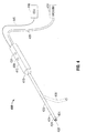
- Fig. 1 is an oblique view of an embodiment of an electrosurgical suction coagulator system in accordance with the present disclosure
- Fig. 2A is a side cutaway view of an embodiment of an electrosurgical suction coagulator in accordance with the present disclosure
- Fig. 2B is a section view of the electrosurgical suction coagulator of Fig. 2A ;
- Fig. 3A is a side cutaway view of another embodiment of an electrosurgical suction coagulator in accordance with the present disclosure
- Fig. 3B is a section view of the electrosurgical suction coagulator of Fig. 3A ;
- Fig. 4 is oblique view of another embodiment an electrosurgical suction coagulator system in accordance with the present disclosure
- Fig. 5A is a side cutaway view of an embodiment of an electrosurgical suction coagulator in accordance with the present disclosure
- Fig. 5B is a side cutaway view of a component of the electrosurgical coagulator of Fig. 5A in accordance with another embodiment of the present disclosure
- Fig. 5C is a side cutaway view of a component of the electrosurgical coagulator of Fig. 5A in accordance with another embodiment of the present disclosure
- Fig. 6A is a side cutaway view of an embodiment of an electrosurgical suction coagulator in accordance with the present disclosure
- Fig. 6B is a side cutaway view of a component of the electrosurgical coagulator of Fig. 6A in accordance with another embodiment of the present disclosure.
- Fig. 6C is a side cutaway view of a component of the electrosurgical coagulator of Fig. 6A in accordance with another embodiment of the present disclosure.
- proximal refers to the end of the apparatus that is closer to the user and the term “distal” refers to the end of the apparatus that is further from the user.
- distal refers to the end of the apparatus that is further from the user.
- an electrosurgical suction coagulator system 100 having a suction coagulator 110 that is operably coupled to an electrosurgical generator 140 via a conductor 145.
- Suction coagulator 110 is operably coupled to a vacuum source 150 by a lumen 155.
- Suction coagulator 110 includes a handle 115 disposed at a proximal end thereof and an elongated shaft 120 extending distally from the handle 115.
- Shaft 120 includes an insulating sheath 126 disposed at least partially thereon. Insulating sheath 126 is formed from any suitable dielectric material, for example, polymeric materials such as PU, PVC, and the like.
- the shaft 120 may be formed from material having malleable or flexible properties, for example without limitation, metallic material such as aluminum and alloys thereof.
- a shaft 120 thus formed may be bent to a desired shape by the user, as shown by way of example by bent shaft 120' (shown in phantom).
- Shaft 120 includes a tube-like electrode 125 for delivering electrosurgical energy to tissue.
- the electrode 125 is disposed coaxially through shaft 120 and is exposed at a distal end 124 of shaft 120 to form an aspiration port 128 defined therethrough.
- Tube-like electrode 125 defines a conduit (not explicitly shown) longitudinally through shaft 120 to provide suction to a surgical site.
- the aspiration port 128 is in fluid communication with vacuum source 150 via lumen 155.
- the outer diameter of tube-like electrode 125 is sized similarly to the inner diameter of shaft 120 to form a press or interference-fit between electrode 125 and shaft 120.
- insulating sheath 126 is configured to provide electrical insulation between electrode 125 and the surface of shaft 120.
- a thermally conductive member 122 Disposed concentrically about shaft 120 and proximal to the distal end 124 thereof is a thermally conductive member 122.
- the diameter of shaft 120 is accordingly sized similarly to the inner diameter of member 122 to form a press or interface-fit between member 122 and shaft 120.
- member 122 may be coupled to shaft 120 by any suitable coupling technique such as, for example, crimping, welding, soldering, adhesive, etc.
- member 122 is positioned relative to shaft 120 so as to sufficiently impede the propagation of thermal energy proximally and/or away from the surgical site and/or the distal end 124 of shaft 120.
- member 122 is formed of a material less thermally conductive than that of shaft 120. More specifically, tube-like electrode 125 has a first thermal conductivity K 1 and member 122 has a second thermal conductivity K 2 that is less than the thermal conductivity K 1 of tube-like electrode 125.
- member 122 may be formed from a suitable thermally conductive material such as, without limitation, stainless steel, steel, polyvinyl chloride (PVC), thermoplastic polymer, etc.
- a suitable insulating material e.g., an insulative coating, a heat-shrink insulator, etc.
- at least a portion of member 122 may be made from a suitable non-conductive material.
- handle 115 includes a control 130 (e.g., handswitch) for controlling the application of electrosurgical energy, i.e., activation and deactivation of an electrosurgical signal.
- Handle 115 includes an additional or second control 131 for controlling the application of suction to the surgical site.
- control 131 may be operably coupled to a valve (not shown) that may be disposed within handle 115, shaft 120, vacuum source 150, and/or lumen 155.
- control 131 may be operably coupled to a regulator, motor control, or other suitable manner of vacuum control.
- a suction coagulator 200 in accordance with the present disclosure is operably coupled to an electrosurgical generator 240 via a conductor 245 and includes a housing 215 disposed proximally to an elongated shaft 220.
- Housing 215 may be a handle.
- Shaft 220 includes an insulating sheath 226 formed from any suitable dielectric material, for example, polymeric materials such as PU, PVC, and the like.
- a tube-like electrode 225 for delivering electrosurgical energy to tissue is disposed coaxially though shaft 220 and is exposed at a distal end 224 of shaft to form an aspiration port 228 defined therethrough.
- Tube-like electrode 225 defines a conduit 230 longitudinally through shaft 220 to provide suction to a surgical site.
- Conduit 230 is in fluid communication with vacuum source 250 via lumen 255.
- Tube-like electrode 224 may be formed from any suitable electrically conductive material, including without limitation, aluminum or stainless steel.
- thermally conductive member 222 is disposed concentrically about shaft 220 and proximal to the distal end 224 thereof.
- thermally conductive member 222 is disposed between about 0.15 inches and about 0.25 inches from the distal end 224 of shaft 220 or disposed a suitable longitudinal distance from distal end 224 of shaft 220 such that during use of suction coagulator 220 member 222 is positioned relative to shaft 220 to efficiently impede the propagation of thermal energy proximally and/or away from the surgical site, the exposed tip of electrode 225, and/or the distal end 224 of shaft 220.
- member 222 may be between about 0.1 inches and about 0.5 inches in longitudinal length or a longitudinal length sufficient to impede the propagation of thermal energy proximally.
- a suction coagulator 300 in accordance with another embodiment the present disclosure is operably coupled to an electrosurgical generator 340 via a conductor 345 and includes a housing 315 disposed proximally to an elongated shaft 320.
- Shaft 320 includes an insulating sheath 326 formed from any suitable dielectric material.
- a tube-like electrode 325 for delivering electrosurgical energy to tissue is disposed coaxially though shaft 320 and is exposed at a distal end 324 of shaft to form an aspiration port 328 defined therethrough.
- Tube-like electrode 325 defines a conduit 330 longitudinally through shaft 320 to provide suction to a surgical site.
- Conduit 330 is in fluid communication with a vacuum source 350 via a lumen 355.
- Tube-like electrode 325 may be formed from any suitable electrically conductive material, including without limitation, aluminum or stainless steel.
- Shaft 320 includes a recess 321 formed concentrically therein and proximal to the distal end 324 thereof.
- a thermally conductive member 322 is disposed concentrically within the recess 321 (e.g., via welding, adhesive, etc.), such that an outer surface 322a of thermally conductive member 322 is substantially coplanar with an outer surface 320a of shaft 320 and the insulating sheath 326 is disposed between thermally conductive member 322 and tube-like electrode 325.
- the diameter of shaft 320 is substantially uniform along at least a majority along the length thereof.
- recess 321 is disposed between about 0.15 inches and about 0.25 inches from the distal end 324 of shaft 320 or disposed a suitable distance from distal end 324 of shaft 320 such that during use of suction coagulator 300, member 322 is positioned relative to shaft 320 to efficiently impede the propagation of thermal energy proximally and/or away from the surgical site and/or the distal end 324 of shaft 320.
- member 322 may be between about 0.1 inches and about 0.5 inches in longitudinal length or a longitudinal length sufficient to impede the propagation of thermal energy proximally.
- the longitudinal length of recess 321 may be varied in accordance with the longitudinal length of member 322 to receive member 322 therein.
- Fig. 4 illustrates another embodiment of the presently disclosed electrosurgical coagulator system shown generally as 400.
- Electrosurgical coagulator system 400 is substantially as described above with respect to system 100 but includes additional features which are discussed in detail below.
- system 400 includes a suction coagulator 410 operably coupled to an electrosurgical generator 440 via a conductor 445 and to a vacuum source 450 by a lumen 455.
- Suction coagulator 410 includes a handle 415 disposed at a proximal end thereof and an elongated shaft 420 extending distally from the handle 415.
- Shaft 420 includes an insulating sheath 426 disposed at least partially thereon.
- Insulating sheath 426 is formed from any suitable dielectric material, for example, polymeric materials such as PU, PVC, and the like.
- the shaft 420 may be formed from material having malleable or flexible properties, for example without limitation, metallic material such as aluminum and alloys thereof.
- a shaft 420 thus formed may be bent to a desired shape by the user, as shown by way of example by bent shaft 420' (shown in phantom).
- Shaft 420 includes a tube-like electrode 425 for delivering electrosurgical energy to tissue.
- the electrode 425 is disposed coaxially through shaft 420 and defines a conduit (not explicitly shown) longitudinally through shaft 420 to provide suction to a surgical site.
- An electrically conductive distal tip 422 is mechanically coupled to a distal end of the tube-like electrode 425 such that the distal tip 422 is exposed at a distal end 424 of shaft 420 to form an aspiration port 428 defined therethrough.
- the distal tip 422 is in electrical communication with tube-like electrode 425 to deliver electrosurgical energy to tissue during a surgical procedure.
- tube-like electrode 425 may be at least partially exposed at the distal end 425 of shaft 420.
- the aspiration port 428 is in fluid communication with vacuum source 450 via lumen 455.
- the outer diameter of tube-like electrode 425 is sized similarly to the inner diameter of shaft 420 to form a press or interference-fit between electrode 425 and shaft 420.
- insulating sheath 426 is configured to provide electrical insulation between electrode 425 and the surface of shaft 420.
- the inner diameter of the distal tip 422 is sized similarly to the outer diameter of tube-like electrode 425 to form a fit (e.g., threaded-fit, press-fit, interface-fit, etc.) between distal tip 422 and tube-like electrode 425. Additionally or alternatively, distal tip 422 may be mechanically coupled to the distal end of tube-like electrode 425 by any suitable coupling technique or combination of coupling techniques such as, for example, crimping, welding, soldering, adhesive, or any combination thereof.
- the distal tip 422 is formed of a material less thermally conductive than that of the shaft 420.
- distal tip 422 may be formed from a suitable thermally conductive material such as, without limitation, stainless steel, steel alloy, lead, aluminum alloy, etc. In this manner, the distal tip 422 operates to sufficiently impede the propagation of thermal energy proximally and/or away from the surgical site and/or the distal end 424 of the shaft 420 during a surgical procedure.
- FIG. 500 another embodiment of the suction coagulator 410 of Fig. 4 is shown generally as 500.
- the suction coagulator 500 is operably coupled to an electrosurgical generator 540 via a conductor 545 and includes a housing 515 disposed proximally to an elongated shaft 520.
- Shaft 520 includes an insulating sheath 526 formed from any suitable dielectric material, for example, polymeric materials such as PU, PVC, and the like.
- a tube-like electrode 525 for delivering electrosurgical energy to tissue is disposed coaxially though shaft 520 and is exposed at a distal end 524 of shaft to form a male threaded portion 535a.
- An electrically conductive distal tip 522 (shown separated from tube-like electrode 525) includes a female threaded portion 535b disposed at least partially within the distal tip 522 and configured to receive male threaded portion 535a therein in a thread-fit manner to mechanically couple distal tip 522 to tube-like electrode 525 and provide electrical communication therebetween to deliver electrosurgical energy to tissue.
- distal tip 522 is exposed at a distal end 524 of shaft 520 to form an aspiration port 528 defined therethrough.
- Tube-like electrode 525 defines a conduit 530 longitudinally through shaft 520 to provide suction to a surgical site via aspiration port 528. Conduit 530 is in fluid communication with vacuum source 550 via lumen 555. Tube-like electrode 525 may be formed from any suitable electrically conductive material, including without limitation, aluminum or stainless steel. In embodiments, tube-like electrode 525 may be at least partially exposed at the distal end 525 of shaft 520.
- the inner diameter of the distal tip 522 is sized similarly to the outer diameter of tube-like electrode 525 to facilitate the threading of female threaded portion 535b of distal tip 522 about male threaded portion 535a of tube-like electrode 525.
- the outer periphery of distal tip 522 may be configured to be substantially coplanar with the outer periphery of shaft 520 and/or insulating sheath 526 or, alternatively, to be substantially coplanar with the outer periphery of tube-like electrode 525.
- distal tip 522 may be between about 0.1 inches and about 0.5 inches in longitudinal length or a longitudinal length sufficient to impede the propagation of thermal energy proximally.
- an embodiment of distal tip 522 may include a wave-like electrical conductor 560 configured to electrically communicate with tube-like electrode 525 when distal tip 522 is threaded to tube-like electrode 525 to deliver electrosurgical energy to tissue during a surgical procedure.
- distal tip 522 includes a thermally conductive polymer or so-called "cool polymer" disposed therein to impede the propagation of thermal energy from electrical conductor 560 during a surgical procedure.
- Fig. 5C shows another embodiment of distal tip 522 having a plurality of vertical electrical conductors 570 intersected by one or more horizontal electrical conductors 572.
- One or more of conductors 570 and 572 are in electrical communication with tube-like electrode 525 when distal tip 522 is threaded to tube-like electrode 525 to deliver electrosurgical energy to tissue during a surgical procedure.
- distal tip 522 includes a thermally conductive polymer or so-called "cool polymer" disposed therein to impede the propagation of thermal energy from electrical conductors 570 and 572 during a surgical procedure.
- FIG. 6A, 6B, and 6C another embodiment of the suction coagulator 410 of Fig. 4 is shown generally as 600.
- the suction coagulator 600 is operably coupled to an electrosurgical generator 640 via a conductor 645 and includes a housing 615 disposed proximally to an elongated shaft 620.
- Shaft 620 includes an insulating sheath 626 formed from any suitable dielectric material, for example, polymeric materials such as PU, PVC, and the like.
- a tube-like electrode 625 for delivering electrosurgical energy to tissue is disposed coaxially though shaft 620 and is exposed at a distal end 624 of shaft.
- Tube-like electrode 625 defines a conduit 630 longitudinally through shaft 620 to provide suction to a surgical site.
- Conduit 630 is in fluid communication with a vacuum source 650 via a lumen 655.
- Tube-like electrode 625 may be formed from any suitable electrically conductive material, including without limitation, aluminum or stainless steel.
- Suction coagulator 600 further includes an electrically conductive distal tip 622 configured to mechanically couple to tube-like electrode 525 and provide electrical communication therebetween to deliver electrosurgical energy to tissue during a surgical procedure.
- Distal tip 622 may be mechanically coupled to tube-like electrode 625 by any suitable coupling technique or combination of coupling techniques such as, for example, press-fit, interface-fit, crimping, welding, soldering, adhesive, or any combination thereof.
- distal tip 622 is exposed at a distal end 624 of shaft 620 to form an aspiration port 628 defined therethrough.
- Tube-like electrode 625 defines a conduit 630 longitudinally through shaft 620 to provide suction to a surgical site via aspiration port 628.
- Tube-like electrode 625 may be formed from any suitable electrically conductive material, including without limitation, aluminum or stainless steel. In embodiments, tube-like electrode 625 may be at least partially exposed at the distal end 625 of shaft 620.
- the inner diameter of the distal tip 622 is sized similarly to the outer diameter of tube-like electrode 625 to facilitate mechanical coupling of distal tip 622 to tube-like electrode 625.
- the outer periphery of distal tip 622 may be configured to be substantially coplanar with the outer periphery of shaft 620 and/or insulating sheath 626 or, alternatively, to be substantially coplanar with the outer periphery of tube-like electrode 625.
- distal tip 622 may be between about 0.1 inches and about 0.5 inches in longitudinal length or a longitudinal length sufficient to impede the propagation of thermal energy proximally.
- an embodiment of distal tip 622 may include a wave-like electrical conductor 660 configured to electrically communicate with tube-like electrode 625 when distal tip 622 is mechanically coupled to tube-like electrode 625 to deliver electrosurgical energy to tissue during a surgical procedure.
- distal tip 622 includes a thermally conductive polymer 665 or so-called "cool polymer” disposed therein to impede the propagation of thermal energy from electrical conductor 660 during a surgical procedure.
- Fig. 6C shows another embodiment of distal tip 622 having a plurality of vertical electrical conductors 670 intersected by one or more horizontal electrical conductors 672.
- One or more of conductors 670 and 672 are in electrical communication with tube-like electrode 625 when distal tip 622 is mechanically coupled to tube-like electrode 625 to deliver electrosurgical energy to tissue during a surgical procedure.
- distal tip 522 includes a thermally conductive polymer or so-called "cool polymer" disposed therein to impede the propagation of thermal energy from electrical conductors 670 and 672 during a surgical procedure.
Landscapes
- Health & Medical Sciences (AREA)
- Surgery (AREA)
- Engineering & Computer Science (AREA)
- Life Sciences & Earth Sciences (AREA)
- Biomedical Technology (AREA)
- Otolaryngology (AREA)
- Nuclear Medicine, Radiotherapy & Molecular Imaging (AREA)
- Plasma & Fusion (AREA)
- Physics & Mathematics (AREA)
- Heart & Thoracic Surgery (AREA)
- Medical Informatics (AREA)
- Molecular Biology (AREA)
- Animal Behavior & Ethology (AREA)
- General Health & Medical Sciences (AREA)
- Public Health (AREA)
- Veterinary Medicine (AREA)
- Surgical Instruments (AREA)
Applications Claiming Priority (1)
| Application Number | Priority Date | Filing Date | Title |
|---|---|---|---|
| US12/388,186 US8444641B2 (en) | 2009-02-18 | 2009-02-18 | Two piece tube for suction coagulator |
Publications (2)
| Publication Number | Publication Date |
|---|---|
| EP2221016A2 true EP2221016A2 (fr) | 2010-08-25 |
| EP2221016A3 EP2221016A3 (fr) | 2010-10-06 |
Family
ID=42227798
Family Applications (1)
| Application Number | Title | Priority Date | Filing Date |
|---|---|---|---|
| EP10153960A Withdrawn EP2221016A3 (fr) | 2009-02-18 | 2010-02-18 | Tuyau en deux pièces pour appareil de coagulation aspirant |
Country Status (5)
| Country | Link |
|---|---|
| US (1) | US8444641B2 (fr) |
| EP (1) | EP2221016A3 (fr) |
| JP (1) | JP5599198B2 (fr) |
| AU (1) | AU2010200605B2 (fr) |
| CA (1) | CA2693458A1 (fr) |
Cited By (1)
| Publication number | Priority date | Publication date | Assignee | Title |
|---|---|---|---|---|
| EP2263585A1 (fr) * | 2009-06-19 | 2010-12-22 | Tyco Healthcare Group, LP | Barrière thermique pour appareil de coagulation aspirant |
Families Citing this family (5)
| Publication number | Priority date | Publication date | Assignee | Title |
|---|---|---|---|---|
| US8454600B2 (en) * | 2009-02-18 | 2013-06-04 | Covidien Lp | Two piece tube for suction coagulator |
| US8460291B2 (en) * | 2009-02-18 | 2013-06-11 | Covidien Lp | Two piece tube for suction coagulator |
| WO2018067870A1 (fr) * | 2016-10-05 | 2018-04-12 | I.C. Medical, Inc. | Lame d'électrochirurgie ultrapolaire, crayon d'électrochirurgie et crayon d'électrochirurgie télescopique ultrapolaires à utiliser dans des modes monopolaire et bipolaire d'esu |
| USD875933S1 (en) | 2017-07-26 | 2020-02-18 | Brian K. Reaux | Medical coagulation and ablation blade |
| CN114515188B (zh) * | 2022-01-17 | 2025-02-11 | 南京智康医疗科技有限公司 | 一种射频等离子手术电极 |
Family Cites Families (77)
| Publication number | Priority date | Publication date | Assignee | Title |
|---|---|---|---|---|
| DE1159574B (de) | 1961-11-29 | 1963-12-19 | Siemens Reiniger Werke Ag | Sicherheitsvorrichtung fuer Hochfrequenz-Chirurgieapparate |
| FR1340509A (fr) | 1962-11-27 | 1963-10-18 | Siemens Reiniger Werke Ag | Dispositif de sécurité pour appareils de chirurgie à haute fréquence |
| GB1222243A (en) | 1967-07-05 | 1971-02-10 | Kearns Tribune Corp | Generating plasma |
| FR2235669A1 (en) | 1973-07-07 | 1975-01-31 | Lunacek Boris | Gynaecological sterilisation instrument - has hollow electrode protruding from the end of a curved ended tube |
| DE2429021C2 (de) | 1974-06-18 | 1983-12-08 | Erbe Elektromedizin GmbH, 7400 Tübingen | Fernschalteinrichtung für ein HF-Chirurgiegerät |
| DE2460481A1 (de) | 1974-12-20 | 1976-06-24 | Delma Elektro Med App | Elektrodenhandgriff zur handfernschaltung eines hochfrequenz-chirurgiegeraets |
| DE3045996A1 (de) | 1980-12-05 | 1982-07-08 | Medic Eschmann Handelsgesellschaft für medizinische Instrumente mbH, 2000 Hamburg | Elektro-chirurgiegeraet |
| NO165661C (no) | 1984-12-11 | 1991-03-20 | Valleylab Inc | Elektrokirurgisk genererings-system. |
| JPS61159953A (ja) | 1985-01-08 | 1986-07-19 | オリンパス光学工業株式会社 | 前立腺切除装置 |
| US4781175A (en) | 1986-04-08 | 1988-11-01 | C. R. Bard, Inc. | Electrosurgical conductive gas stream technique of achieving improved eschar for coagulation |
| SU1438745A1 (ru) | 1986-12-24 | 1988-11-23 | Всесоюзный научно-исследовательский и испытательный институт медицинской техники | Ультразвуковой хирургический инструмент |
| US4978338A (en) | 1988-04-21 | 1990-12-18 | Therex Corp. | Implantable infusion apparatus |
| US4932952A (en) | 1988-12-20 | 1990-06-12 | Alto Development Corporation | Antishock, anticlog suction coagulator |
| US5460602A (en) | 1989-01-23 | 1995-10-24 | Shapira; Nadiv | Smoke evacuator for smoke generating devices |
| US5088997A (en) | 1990-03-15 | 1992-02-18 | Valleylab, Inc. | Gas coagulation device |
| US5098430A (en) | 1990-03-16 | 1992-03-24 | Beacon Laboratories, Inc. | Dual mode electrosurgical pencil |
| US5133714A (en) | 1991-05-06 | 1992-07-28 | Kirwan Surgical Products, Inc. | Electrosurgical suction coagulator |
| DE4121977C2 (de) | 1991-07-03 | 1994-10-27 | Wolf Gmbh Richard | Medizinisches Instrument mit einem kontaktlosen Schalter zum Steuern externer Geräte |
| JP3465230B2 (ja) | 1991-08-16 | 2003-11-10 | ミリアドレイズ インコーポレイテツド | レーザ伝送ファイバの側方反射チップ |
| DE9117019U1 (de) | 1991-11-27 | 1995-03-09 | Erbe Elektromedizin GmbH, 72072 Tübingen | Einrichtung zur Koagulation biologischer Gewebe |
| DE4139029C2 (de) | 1991-11-27 | 1996-05-23 | Erbe Elektromedizin | Einrichtung zur Koagulation biologischer Gewebe |
| DE9117299U1 (de) | 1991-11-27 | 2000-03-23 | Erbe Elektromedizin GmbH, 72072 Tübingen | Einrichtung zur Koagulation biologischer Gewebe |
| US6102046A (en) | 1995-11-22 | 2000-08-15 | Arthrocare Corporation | Systems and methods for electrosurgical tissue revascularization |
| US5720745A (en) | 1992-11-24 | 1998-02-24 | Erbe Electromedizin Gmbh | Electrosurgical unit and method for achieving coagulation of biological tissue |
| US5693044A (en) | 1992-12-11 | 1997-12-02 | Cosmescu; Ioan | Telescopic surgical device and method therefor |
| DE4326037C2 (de) | 1993-08-03 | 1997-01-16 | Dieter C Dr Med Goebel | Lasereinrichtung |
| ES2149241T3 (es) | 1993-11-10 | 2000-11-01 | Xomed Inc | Instrumento electroquirurgico bipolar y metodo de fabricacion. |
| US5730742A (en) | 1994-08-04 | 1998-03-24 | Alto Development Corporation | Inclined, flared, thermally-insulated, anti-clog tip for electrocautery suction tubes |
| US5520685A (en) | 1994-08-04 | 1996-05-28 | Alto Development Corporation | Thermally-insulated anti-clog tip for electrocautery suction tubes |
| US6213999B1 (en) | 1995-03-07 | 2001-04-10 | Sherwood Services Ag | Surgical gas plasma ignition apparatus and method |
| US5669904A (en) | 1995-03-07 | 1997-09-23 | Valleylab Inc. | Surgical gas plasma ignition apparatus and method |
| US6264650B1 (en) | 1995-06-07 | 2001-07-24 | Arthrocare Corporation | Methods for electrosurgical treatment of intervertebral discs |
| WO1996039086A1 (fr) | 1995-06-06 | 1996-12-12 | Valleylab Inc. | Regulation electrique d'un generateur electrochirurgical |
| US6458125B1 (en) | 1995-07-10 | 2002-10-01 | I. C. Medical, Inc. | Electro-surgical unit pencil apparatus and method therefor |
| DE19537897A1 (de) | 1995-09-19 | 1997-03-20 | Erbe Elektromedizin | Multifunktionales chirurgisches Instrument |
| US5989249A (en) | 1996-04-29 | 1999-11-23 | Kirwan Surgical Products, Inc. | Bipolar suction coagulator |
| DE29724247U1 (de) | 1997-03-20 | 2000-08-03 | Erbe Elektromedizin GmbH, 72072 Tübingen | Einrichtung zur Koagulation biologischer Gewebe |
| US5854455A (en) | 1997-03-25 | 1998-12-29 | Ut Automotive Dearborn, Inc. | Switching device with secondary switching function |
| US5968042A (en) | 1997-06-17 | 1999-10-19 | Ernster; Joel A. | Monopolar suction coagulator |
| US5954686A (en) | 1998-02-02 | 1999-09-21 | Garito; Jon C | Dual-frequency electrosurgical instrument |
| DE19820240C2 (de) | 1998-05-06 | 2002-07-11 | Erbe Elektromedizin | Elektrochirurgisches Instrument |
| US6458126B1 (en) | 1998-09-19 | 2002-10-01 | Donald E. Doyle | Electrosurgical suction and coagulation instrument |
| DE19848784C2 (de) | 1998-10-22 | 2003-05-08 | Erbe Elektromedizin | Sonde |
| EP1050279B1 (fr) | 1999-05-03 | 2006-06-21 | Jon C. Garito | Piéce à main électrochirurgicale pour le traitement d'un tissue |
| US6206878B1 (en) | 1999-05-07 | 2001-03-27 | Aspen Laboratories, Inc. | Condition responsive gas flow adjustment in gas-assisted electrosurgery |
| US6238388B1 (en) | 1999-09-10 | 2001-05-29 | Alan G. Ellman | Low-voltage electrosurgical apparatus |
| US6379350B1 (en) | 1999-10-05 | 2002-04-30 | Oratec Interventions, Inc. | Surgical instrument for ablation and aspiration |
| US6475217B1 (en) | 1999-10-05 | 2002-11-05 | Sherwood Services Ag | Articulating ionizable gas coagulator |
| US6616660B1 (en) | 1999-10-05 | 2003-09-09 | Sherwood Services Ag | Multi-port side-fire coagulator |
| EP1602337B1 (fr) | 1999-10-05 | 2007-12-19 | Covidien AG | Appareil de coagulation à gaz ionisable à délflexion |
| CA2320652C (fr) | 1999-10-05 | 2011-01-11 | Sherwood Services Ag | Systeme a tourbillon pour unite de coagulation a gaz ionisable |
| EP1681025B1 (fr) | 2000-02-16 | 2010-10-27 | Covidien AG | Appareil pour l'électrochirurgie assisté par un gaz inerte |
| AU2001243234A1 (en) | 2000-02-23 | 2001-09-03 | United States Surgical, A Division Of Tyco Healthcare Group | Adhesive applicator |
| JP4502565B2 (ja) | 2000-02-28 | 2010-07-14 | コンメド コーポレイション | 珪素被覆が直接接着された電気外科手術用メス |
| US6406476B1 (en) * | 2000-08-15 | 2002-06-18 | Kirwan Surgical Products, Inc. | Bipolar, fluid assisted coagulator/ablator probe for arthroscopy |
| US6773438B1 (en) | 2000-10-19 | 2004-08-10 | Ethicon Endo-Surgery | Surgical instrument having a rotary lockout mechanism |
| US6447524B1 (en) | 2000-10-19 | 2002-09-10 | Ethicon Endo-Surgery, Inc. | Fastener for hernia mesh fixation |
| US7485124B2 (en) | 2000-10-19 | 2009-02-03 | Ethicon Endo-Surgery, Inc. | Surgical instrument having a fastener delivery mechanism |
| JP4067403B2 (ja) | 2000-12-15 | 2008-03-26 | コビディエン アクチェンゲゼルシャフト | 電気外科電極シュラウド |
| US7175336B2 (en) | 2001-01-26 | 2007-02-13 | Depuy Acromed, Inc. | Graft delivery system |
| US6652514B2 (en) | 2001-09-13 | 2003-11-25 | Alan G. Ellman | Intelligent selection system for electrosurgical instrument |
| US20030181904A1 (en) | 2002-01-23 | 2003-09-25 | Levine Andy H. | Electrosurgical cutting, coagulating and suction instrument |
| EP1524946B1 (fr) | 2002-07-25 | 2012-10-17 | Covidien AG | Electrocautere a capacite de detection de resistance |
| DE10253819A1 (de) | 2002-11-18 | 2004-07-01 | Storz Endoskop Produktions Gmbh | Elektrochirurgische Vorrichtung sowie Verfahren zum Betreiben derselben |
| EP1949867B1 (fr) | 2003-02-20 | 2013-07-31 | Covidien AG | Détecteur de mouvement pour contrôler un résultat électrochirurgical |
| EP1635690B1 (fr) | 2003-05-01 | 2011-12-28 | Covidien AG | Appareil de coagulation aspirant equipe d'une sonde de dissection |
| AU2003904278A0 (en) | 2003-08-13 | 2003-08-28 | Thomas J. Borody | Improved oral oxygenating device |
| AU2003294390A1 (en) | 2003-11-20 | 2005-07-14 | Sherwood Services Ag | Electrosurgical pencil with plurality of controls |
| US7628787B2 (en) | 2004-02-03 | 2009-12-08 | Covidien Ag | Self contained, gas-enhanced surgical instrument |
| JP2006000404A (ja) * | 2004-06-17 | 2006-01-05 | Olympus Corp | 外科用処置具 |
| JP2006006692A (ja) * | 2004-06-28 | 2006-01-12 | Allan Ellman | アデノイド切除刀電気外科用プローブ |
| US7553309B2 (en) | 2004-10-08 | 2009-06-30 | Covidien Ag | Electrosurgical system employing multiple electrodes and method thereof |
| US8216234B2 (en) | 2004-11-10 | 2012-07-10 | Ethicon Endo-Surgery, Inc. | Tissue resection device |
| US8267934B2 (en) | 2005-04-13 | 2012-09-18 | Stryker Corporation | Electrosurgical tool |
| US8449537B2 (en) | 2006-12-29 | 2013-05-28 | St. Jude Medical, Atrial Fibrillation Division, Inc. | Ablation catheter with thermally mediated catheter body for mitigating blood coagulation and creating larger lesion |
| US8460291B2 (en) * | 2009-02-18 | 2013-06-11 | Covidien Lp | Two piece tube for suction coagulator |
| US8454600B2 (en) * | 2009-02-18 | 2013-06-04 | Covidien Lp | Two piece tube for suction coagulator |
-
2009
- 2009-02-18 US US12/388,186 patent/US8444641B2/en not_active Expired - Fee Related
-
2010
- 2010-02-18 AU AU2010200605A patent/AU2010200605B2/en not_active Ceased
- 2010-02-18 JP JP2010034134A patent/JP5599198B2/ja not_active Expired - Fee Related
- 2010-02-18 CA CA2693458A patent/CA2693458A1/fr not_active Abandoned
- 2010-02-18 EP EP10153960A patent/EP2221016A3/fr not_active Withdrawn
Cited By (2)
| Publication number | Priority date | Publication date | Assignee | Title |
|---|---|---|---|---|
| EP2263585A1 (fr) * | 2009-06-19 | 2010-12-22 | Tyco Healthcare Group, LP | Barrière thermique pour appareil de coagulation aspirant |
| US8753341B2 (en) | 2009-06-19 | 2014-06-17 | Covidien Lp | Thermal barrier for suction coagulator |
Also Published As
| Publication number | Publication date |
|---|---|
| JP2010188133A (ja) | 2010-09-02 |
| AU2010200605B2 (en) | 2014-01-23 |
| JP5599198B2 (ja) | 2014-10-01 |
| US8444641B2 (en) | 2013-05-21 |
| US20100211067A1 (en) | 2010-08-19 |
| EP2221016A3 (fr) | 2010-10-06 |
| CA2693458A1 (fr) | 2010-08-18 |
| AU2010200605A1 (en) | 2010-09-02 |
Similar Documents
| Publication | Publication Date | Title |
|---|---|---|
| EP2156803B1 (fr) | Tuyau isolé pour appareil de coagulation aspirant | |
| US8454600B2 (en) | Two piece tube for suction coagulator | |
| US12220161B2 (en) | Medical devices and related methods | |
| US9028490B2 (en) | Suction coagulator | |
| US9848932B2 (en) | Cool-tip thermocouple including two-piece hub | |
| US8444641B2 (en) | Two piece tube for suction coagulator | |
| US8460291B2 (en) | Two piece tube for suction coagulator | |
| US8286339B2 (en) | Two piece tube for suction coagulator | |
| US7118569B2 (en) | Bipolar resectoscope electrode | |
| US8753341B2 (en) | Thermal barrier for suction coagulator | |
| US12102375B2 (en) | Systems and methods for tissue coagulation | |
| US20250235253A1 (en) | Medical devices and related methods for delivering energy and/or fluid | |
| US20260020901A1 (en) | Treatment tool for endoscope | |
| US20240348034A1 (en) | An interface joint for an electrosurgical apparatus | |
| HK40037604A (en) | Electrosurgical instrument | |
| CN114746041A (zh) | 电外科器械 |
Legal Events
| Date | Code | Title | Description |
|---|---|---|---|
| PUAI | Public reference made under article 153(3) epc to a published international application that has entered the european phase |
Free format text: ORIGINAL CODE: 0009012 |
|
| AK | Designated contracting states |
Kind code of ref document: A2 Designated state(s): AT BE BG CH CY CZ DE DK EE ES FI FR GB GR HR HU IE IS IT LI LT LU LV MC MK MT NL NO PL PT RO SE SI SK SM TR |
|
| AX | Request for extension of the european patent |
Extension state: AL BA RS |
|
| PUAL | Search report despatched |
Free format text: ORIGINAL CODE: 0009013 |
|
| AK | Designated contracting states |
Kind code of ref document: A3 Designated state(s): AT BE BG CH CY CZ DE DK EE ES FI FR GB GR HR HU IE IS IT LI LT LU LV MC MK MT NL NO PL PT RO SE SI SK SM TR |
|
| AX | Request for extension of the european patent |
Extension state: AL BA RS |
|
| 17P | Request for examination filed |
Effective date: 20110406 |
|
| 17Q | First examination report despatched |
Effective date: 20110926 |
|
| STAA | Information on the status of an ep patent application or granted ep patent |
Free format text: STATUS: THE APPLICATION IS DEEMED TO BE WITHDRAWN |
|
| 18D | Application deemed to be withdrawn |
Effective date: 20120207 |