EP2221148A2 - Hammerplatte für ein Nagelsetzgerät - Google Patents
Hammerplatte für ein Nagelsetzgerät Download PDFInfo
- Publication number
- EP2221148A2 EP2221148A2 EP10153507A EP10153507A EP2221148A2 EP 2221148 A2 EP2221148 A2 EP 2221148A2 EP 10153507 A EP10153507 A EP 10153507A EP 10153507 A EP10153507 A EP 10153507A EP 2221148 A2 EP2221148 A2 EP 2221148A2
- Authority
- EP
- European Patent Office
- Prior art keywords
- housing portion
- housing
- extending
- strike plate
- upper housing
- Prior art date
- Legal status (The legal status is an assumption and is not a legal conclusion. Google has not performed a legal analysis and makes no representation as to the accuracy of the status listed.)
- Granted
Links
- 230000003116 impacting effect Effects 0.000 claims abstract description 24
- 239000000463 material Substances 0.000 description 7
- JOYRKODLDBILNP-UHFFFAOYSA-N Ethyl urethane Chemical compound CCOC(N)=O JOYRKODLDBILNP-UHFFFAOYSA-N 0.000 description 2
- 230000006835 compression Effects 0.000 description 2
- 238000007906 compression Methods 0.000 description 2
- 238000009432 framing Methods 0.000 description 2
- 238000012986 modification Methods 0.000 description 2
- 230000004048 modification Effects 0.000 description 2
- 229910001220 stainless steel Inorganic materials 0.000 description 2
- 239000010935 stainless steel Substances 0.000 description 2
- 239000002023 wood Substances 0.000 description 2
- 244000043261 Hevea brasiliensis Species 0.000 description 1
- 230000004075 alteration Effects 0.000 description 1
- 238000013459 approach Methods 0.000 description 1
- 238000007664 blowing Methods 0.000 description 1
- 238000009435 building construction Methods 0.000 description 1
- 230000009194 climbing Effects 0.000 description 1
- 238000004891 communication Methods 0.000 description 1
- 238000010276 construction Methods 0.000 description 1
- 238000013461 design Methods 0.000 description 1
- 239000002184 metal Substances 0.000 description 1
- 229920003052 natural elastomer Polymers 0.000 description 1
- 229920001194 natural rubber Polymers 0.000 description 1
- 229920003225 polyurethane elastomer Polymers 0.000 description 1
- 230000001737 promoting effect Effects 0.000 description 1
- 238000013022 venting Methods 0.000 description 1
Images


Classifications
-
- B—PERFORMING OPERATIONS; TRANSPORTING
- B25—HAND TOOLS; PORTABLE POWER-DRIVEN TOOLS; MANIPULATORS
- B25C—HAND-HELD NAILING OR STAPLING TOOLS; MANUALLY OPERATED PORTABLE STAPLING TOOLS
- B25C1/00—Hand-held nailing tools; Nail feeding devices
- B25C1/04—Hand-held nailing tools; Nail feeding devices operated by fluid pressure, e.g. by air pressure
- B25C1/047—Mechanical details
-
- B—PERFORMING OPERATIONS; TRANSPORTING
- B25—HAND TOOLS; PORTABLE POWER-DRIVEN TOOLS; MANIPULATORS
- B25C—HAND-HELD NAILING OR STAPLING TOOLS; MANUALLY OPERATED PORTABLE STAPLING TOOLS
- B25C1/00—Hand-held nailing tools; Nail feeding devices
Definitions
- This invention relates to the field of devices used to drive fasteners into work pieces and particularly to a device for impacting fasteners into work pieces.
- Fasteners such as nails and staples are commonly used in projects ranging from crafts to building construction. While manually driving such fasteners into a work piece is effective, a user may quickly become fatigued when involved in projects requiring a large number of fasteners and/or large fasteners. Moreover, proper driving of larger fasteners into a work piece frequently requires more than a single impact from a manual tool.
- the top of a pneumatic nailer is typically somewhat flat and can be used as a manual impacting tool without exposing the hands of the user to the impact. Thus, users frequently use the top portion of the pneumatic tool housing as an impacting surface.
- the housing of pneumatic tools is not commonly designed to withstand impacting forces.
- pneumatic nailers are typically vented through the top of the device.
- a deflector is positioned on the top of the pneumatic nailer to direct the vented air away from the user.
- the deflector may be mounted to the upper housing of the tool or the deflector may be formed integrally with the device housing.
- the deflector which is inherently weaker than other parts of the pneumatic nailer housing, is the part of the pneumatic nailer most frequently used as an impacting device.
- the deflector is one of the most frequently damaged components of a pneumatic nailer.
- What is needed is a device incorporating an element which can be used to absorb energy from an impact. What is further needed is a device incorporating an element which is simple, reliable, lightweight, and compact. A further need exists for a device that incorporates an energy absorbing element that has a long useful lifetime and that does not require extensive redesign of the device.
- a device for impacting a fastener that includes a housing with an upper housing portion, a middle housing portion, and a side housing portion extending between the upper housing portion and the middle housing portion, a drive cylinder configured to vent within the housing, an air passage extending through the housing and including a mouth at the upper housing portion, and a strike plate extending over the upper housing portion and including a top portion positioned apart from the upper housing portion, and a first side extension extending downwardly from the top portion along the side housing portion to a location above and spaced apart from an outwardly extending first surface of the middle housing portion.
- a device for impacting a fastener including a housing with an upper housing portion, a middle housing portion, and a side housing portion extending between the upper housing portion and the middle housing portion, a drive cylinder configured to vent within the housing, an air passage extending through the housing and configured to vent the housing, a strike plate extending over the upper housing portion and including a top portion, and a first side extension extending downwardly from the top portion along the side housing portion to a location above and spaced apart from an outwardly extending first surface of the middle housing portion, and a gasket positioned between the upper housing portion and the top portion of the strike plate.
- a device for impacting a fastener includes a housing including an upper housing and a lower housing, a drive cylinder positioned within the housing and configured to vent into the housing, an air passage extending from within the housing to without the housing, a strike plate including a top surface positioned above the upper housing, and a first side extension extending downwardly from the top surface toward the lower housing to a location above and spaced apart from a horizontal surface of the upper housing, and a gasket positioned between the top of the upper housing and the top surface of the strike plate.
- FIG. 1 depicts a front perspective view of a fastener impacting device in accordance with principles of the present invention
- FIG. 2 depicts a partial simplified side cross sectional view of the drive section of the fastener impacting device of FIG. 1 ;
- FIG. 3 depicts a top perspective view of the strike plate of the device of FIG. 1 ;
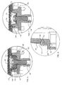
- FIG. 4 depicts a front cross sectional view of the upper housing of the device of FIG. 1 showing a strike plate spaced apart from the upper housing by a gasket, the strike plate including extensions which terminate above an outwardly extending surface of the flange of the housing;
- FIG. 5 depicts a side cross sectional view of the upper housing of the device of FIG. 1 showing a rib of the strike plate, the strike plate fastened to the upper housing by two fasteners;
- FIG. 6 depicts a partial side cross sectional view of the upper housing of the device of FIG. 1 with a fastener extending through the strike plate and gasket;
- FIG. 7 depicts a partial side cross sectional view of the upper housing of the device of FIG. 1 with a fastener extending through the strike plate with an alternative gasket positioned between the strike plate and the upper housing;
- FIG. 8 depicts a partial front cross sectional view of an extension extending into a channel and spaced apart from a horizontal surface of the housing by a gap.
- FIG. 1 depicts a fastener impacting device 100 including a housing 102 and a fastener cartridge 104.
- the housing 102 includes a lower housing 106 and an upper housing 108.
- the housing 102 further defines a handle portion 110, and an air receptacle portion 112.
- a trigger 114 extends outwardly from the housing 102 and controls the supply of compressed air which is provided from a source of compressed air through an air supply hose 116.
- a strike plate 118 is located at the upper end portion of the upper housing 108.
- the fastener cartridge 104 in this embodiment is spring biased to force fasteners, such as nails or staples, serially one after the other, into a loaded position adjacent a drive section 120, shown in FIG. 2 , within the lower housing 106.
- the drive section 120 includes a piston 122 located within a drive cylinder 124.
- a drive blade 126 is located at one end of the piston 122 and aligned with a drive channel 128 into which a fastener to be driven is forced by the fastener cartridge 104.
- a bumper 130 is positioned at the end portion 132 of the cylinder 124 which opens to the drive channel 128.
- the strike plate 118 shown in additional detail in FIGs. 3-5 , includes a top surface 140 and two extensions 142 and 144.
- the top surface 140 is textured and surrounded by a rib 146 which provides additional strength for the strike plate 118.
- the strike plate 118 is attached to the upper housing 108 by two fasteners 148 and 150 inserted through two fastener wells 152 and 154 in the strike plate 118.
- the wells 152 and 154 are used to attach the strike plate 118 to the upper housing 108 as discussed with further reference to the fastener well 152 shown in FIG. 6 .
- the fastener well 152 of the strike plate 118 is positioned within a fastener well 158 of the upper housing 108.
- a fastener bore 160 is located at a lower portion of the well 152.
- a gasket 164 extends along the housing 108.
- a cup 166 is located within the fastener well 152 and includes a lip 168 that extends downwardly through the fastener bore 160 to a location adjacent the gasket 164 and abutting the housing 108.
- the fastener 148 clamps the cup 166 against the fastener well 152 and against the housing 108.
- the gasket 164 is formed to maintain a passage 170 between the upper housing 108 and the underside 172 of the top surface 140 between a vent 174 and the atmosphere.
- the vent 174 provides an air passage venting the interior of the housing 102 to atmosphere. Additional vents and passages may be provided.
- the gasket 164 may be formed to extend between the upper housing 108 and the strike plate 118 along the two extensions 142 and 144.
- FIG. 7 depicts a configuration of a gasket 174 that may be used with the fastener impacting device 100.
- the gasket 174 terminates prior to extending into the fastener well 158 of the upper housing 108 and a washer 176 is located between the fastener 148 and the strike plate 118.
- the thickness of the gasket 174, the depth of the fastener well 152, and the depth of the fastener well 158 are selected to establish an air gap 178 between the fastener well 152 and the fastener well 158.
- the extensions 142 and 144 extend from the top surface 140 along the side of the upper housing 108 to a flange 180 located at a lower portion 182 of the upper housing 108.
- the flange 180 includes a channel 184 with a bottom 186.
- the bottom 186 of the channel 184 is located opposite and parallel to a ledge 188 on the inside of the housing 108 which contacts an upper surface of the lower housing 106.
- the extension 144 includes a base portion 190 which is spaced apart from, and substantially perpendicular to, the bottom 186 of the channel 184.
- the extension 142 also includes a base portion 192 which is spaced apart from a channel bottom 194.
- an operator using the fastener impacting device 100 as a manual impacting device on an object will move the fastener impacting device in the direction of the arrow 196. Accordingly, the strike plate 118 will impact the object (not shown). Upon impact, a force opposite to the direction of the arrow 196 will be generated on the top surface 140 of the strike plate 118.
- the strike plate 118 in this embodiment is made from a stainless steel sheet. Accordingly, the impacting force is initially translated into movement of the strike plate 118 toward the housing 108.
- the gasket 164 is formed using a urethane material.
- Other materials that may be used as a gasket material include natural rubber and microcellular polyurethane elastomer (MPE).
- MPEs form a material with numerous randomly oriented air chambers. Some of the air chambers are closed and some are linked. Additionally, the linked air chambers have varying degrees of communication between the chambers and the orientation of the linked chambers varies. Accordingly, when the MPE structure is compressed, air in the chambers is compressed. As the air is compressed, some of the air remains within various chambers, some of the air migrates between other chambers and some of the air is expelled from the structure. MPEs thus exhibit good impact absorbing characteristics.
- MPE is MH 24-65, commercially available from Elastogran GmbH under the trade name CELLASTO®.
- the thickness of the gasket 164 is selected to be slightly less than the initial gap between the base portions 190 and 192 and the channel bottoms 186 and 194. Accordingly, as the gasket 164 approaches full compression, the base portions 190 and 192 contact the channel bottoms 186 and 194, respectively. Accordingly, any residual energy is transferred directly from the base portions 190 and 192 to the channel bottoms 186 and 194.
- the lower portion 182 of the upper housing 108 is relatively thick and is thus able to absorb increased amounts of force. Moreover, because the ledge 188 is positioned directly in line with an upper surface of the lower housing 106, force is readily transmitted into the lower housing 106. Depending upon the particular materials and design, the foregoing sequence of events may differ. Accordingly, by varying the thickness of the gasket 164 and the gap between the base portions 190 and 192 and the channel bottoms 186 and 194, along with selection of specific materials for the strike plate 118 and the gasket 164, selective amounts of impact force may be directed away from the top of the housing 108.
Landscapes
- Engineering & Computer Science (AREA)
- Mechanical Engineering (AREA)
- Physics & Mathematics (AREA)
- Fluid Mechanics (AREA)
- Portable Nailing Machines And Staplers (AREA)
Applications Claiming Priority (1)
| Application Number | Priority Date | Filing Date | Title |
|---|---|---|---|
| US12/389,463 US8028881B2 (en) | 2009-02-20 | 2009-02-20 | Nailer strike plate |
Publications (3)
| Publication Number | Publication Date |
|---|---|
| EP2221148A2 true EP2221148A2 (de) | 2010-08-25 |
| EP2221148A3 EP2221148A3 (de) | 2010-12-29 |
| EP2221148B1 EP2221148B1 (de) | 2018-04-11 |
Family
ID=42173212
Family Applications (1)
| Application Number | Title | Priority Date | Filing Date |
|---|---|---|---|
| EP10153507.8A Active EP2221148B1 (de) | 2009-02-20 | 2010-02-12 | Hammerplatte für ein Nagelsetzgerät |
Country Status (4)
| Country | Link |
|---|---|
| US (1) | US8028881B2 (de) |
| EP (1) | EP2221148B1 (de) |
| CN (1) | CN101973019B (de) |
| TW (1) | TWI554369B (de) |
Cited By (3)
| Publication number | Priority date | Publication date | Assignee | Title |
|---|---|---|---|---|
| USD677543S1 (en) * | 2011-12-20 | 2013-03-12 | Techtronic Power Tools Technology Limited | Angle finish nailer |
| USD756740S1 (en) * | 2014-06-02 | 2016-05-24 | Stanley Fastening Systems, L.P. | Pneumatic nailer |
| USD756739S1 (en) * | 2014-06-02 | 2016-05-24 | Stanley Fastening Systems, L.P. | Pneumatic nailer |
Families Citing this family (4)
| Publication number | Priority date | Publication date | Assignee | Title |
|---|---|---|---|---|
| US7870987B1 (en) * | 2009-06-30 | 2011-01-18 | Robert Bosch Gmbh | Fastener driving tool with protection inserts |
| CN201604139U (zh) * | 2009-12-30 | 2010-10-13 | 南京德朔实业有限公司 | 手持式电动工具 |
| TWI629145B (zh) * | 2017-03-01 | 2018-07-11 | 郭泓成 | Simple nailer |
| US11654544B2 (en) * | 2020-06-03 | 2023-05-23 | Snap-On Incorporated | Insert for a power tool housing |
Family Cites Families (19)
| Publication number | Priority date | Publication date | Assignee | Title |
|---|---|---|---|---|
| DE1099479B (de) * | 1957-12-24 | 1961-02-09 | Dieter Haubold | Griffausbildung fuer pressluftbetaetigte Schlaggeraete |
| US4197974A (en) * | 1978-06-12 | 1980-04-15 | Speedfast Corporation | Nailer |
| US4404894A (en) * | 1980-08-27 | 1983-09-20 | Hilti Aktiengesellschaft | Valve trigger assembly for pneumatic nailer |
| US5080273A (en) * | 1989-12-19 | 1992-01-14 | Duo-Fast Corporation | Trigger valve and safety mechanism for fastener driving tool |
| DE29500073U1 (de) * | 1995-01-04 | 1995-03-02 | Joh. Friedrich Behrens AG, 22926 Ahrensburg | Eintreibgerät für Befestigungsmittel |
| US5560528A (en) * | 1995-05-11 | 1996-10-01 | Testo Industry Corp. | Exhaust hood mounting structure for pneumatic nail guns |
| EP0747175B1 (de) * | 1995-06-09 | 2003-08-27 | Max Co., Ltd. | Auslasssystem für eine Maschine zum Eintreiben von Nägeln |
| US20030057248A1 (en) * | 1999-09-10 | 2003-03-27 | Bruins Roger C. | Automatic washer feeder for automatic nailer |
| US6199383B1 (en) * | 1999-02-11 | 2001-03-13 | Snap-On Tools Company | Pneumatic tool and air deflector boot therefor |
| US6059166A (en) * | 1999-11-01 | 2000-05-09 | Basso Industry Corp. | Exhausted air dispensing device for a power nailer |
| US6296168B1 (en) * | 2001-01-16 | 2001-10-02 | Basso Industry Corp. | Engagement structure between a cover and an end cap on a rear end of a power nailer |
| US6671931B1 (en) * | 2001-06-25 | 2004-01-06 | David Duncan | Vibrating hammer glove |
| TW585152U (en) * | 2001-07-27 | 2004-04-21 | Wang-Kuan Lin | Upper lid seat structure for nailing gun |
| JP4996044B2 (ja) * | 2004-07-09 | 2012-08-08 | 日立工機株式会社 | 打込機 |
| TWM299059U (en) * | 2006-03-23 | 2006-10-11 | An Puu Hsin Co Ltd | Structure of rotating air-exhaust cover of nailing gun |
| US7341173B1 (en) * | 2006-10-05 | 2008-03-11 | Arnold John L | Exhaust gas diffuser and filter system for a pneumatic nail gun |
| US7475800B2 (en) * | 2007-05-01 | 2009-01-13 | Depoan Pneumatic Corp. | Trigger valve for pneumatic nail gun |
| US20080290132A1 (en) * | 2007-05-24 | 2008-11-27 | Chia-Sheng Liang | Main Air Valve for Pneumatic Nail Gun |
| US7686198B2 (en) * | 2008-07-25 | 2010-03-30 | De Poan Pneumatic Corp. | Nail gun bushing and cylinder valve arrangement |
-
2009
- 2009-02-20 US US12/389,463 patent/US8028881B2/en not_active Expired - Fee Related
-
2010
- 2010-02-12 TW TW099104636A patent/TWI554369B/zh not_active IP Right Cessation
- 2010-02-12 EP EP10153507.8A patent/EP2221148B1/de active Active
- 2010-02-20 CN CN201010171165.7A patent/CN101973019B/zh not_active Expired - Fee Related
Non-Patent Citations (1)
| Title |
|---|
| None |
Cited By (3)
| Publication number | Priority date | Publication date | Assignee | Title |
|---|---|---|---|---|
| USD677543S1 (en) * | 2011-12-20 | 2013-03-12 | Techtronic Power Tools Technology Limited | Angle finish nailer |
| USD756740S1 (en) * | 2014-06-02 | 2016-05-24 | Stanley Fastening Systems, L.P. | Pneumatic nailer |
| USD756739S1 (en) * | 2014-06-02 | 2016-05-24 | Stanley Fastening Systems, L.P. | Pneumatic nailer |
Also Published As
| Publication number | Publication date |
|---|---|
| CN101973019A (zh) | 2011-02-16 |
| TWI554369B (zh) | 2016-10-21 |
| EP2221148B1 (de) | 2018-04-11 |
| TW201039987A (en) | 2010-11-16 |
| US8028881B2 (en) | 2011-10-04 |
| US20100213234A1 (en) | 2010-08-26 |
| CN101973019B (zh) | 2014-10-01 |
| EP2221148A3 (de) | 2010-12-29 |
Similar Documents
| Publication | Publication Date | Title |
|---|---|---|
| EP2221148B1 (de) | Hammerplatte für ein Nagelsetzgerät | |
| US7975777B2 (en) | Cellular foam bumper for nailer | |
| US5370192A (en) | One piece combination chisel/hammer/crowbar devices | |
| AU2007342410B2 (en) | Cordless fastener tool with fastener driving and rotating functions | |
| NZ526029A (en) | Framing tool with automatic fastener-size adjustment | |
| CA2307507C (en) | Shock absorption system for a striking tool | |
| CA2735399A1 (en) | Combustion power source with back pressure release for combustion powered fastener-driving tool | |
| WO2000043165A3 (en) | Nonrecoil hammer | |
| SI1098738T1 (en) | Nailing device for belt nails | |
| US7562801B2 (en) | Stapler with guide | |
| US6863204B2 (en) | Hammer-type stapler with cartridge | |
| US20060065693A1 (en) | Multi-purpose nail driver | |
| US4646852A (en) | Pneumatic mallet | |
| US20060086209A1 (en) | Powered pulse shingle and nail remover/demolition | |
| US20060043139A1 (en) | Cage and offset upper probe assembly for fastener-driving tool | |
| US7159747B1 (en) | Method and apparatus for installing a carpeting tack strip | |
| JP5262033B2 (ja) | 携帯用動力工具 | |
| US20190376295A1 (en) | Pneumatic roofing material removal tool | |
| US20040149086A1 (en) | Attachment for a tool | |
| JP5125741B2 (ja) | 携帯用動力工具 | |
| JP4569521B2 (ja) | 打込機 | |
| JP2007030047A (ja) | 打込み工具のコンタクトにおけるオフセット構造 | |
| KR200254372Y1 (ko) | 자동 못박음 장치 | |
| KR20030017281A (ko) | 자동 못박음 장치 | |
| JP3937821B2 (ja) | ファスナー打込み工具 |
Legal Events
| Date | Code | Title | Description |
|---|---|---|---|
| PUAI | Public reference made under article 153(3) epc to a published international application that has entered the european phase |
Free format text: ORIGINAL CODE: 0009012 |
|
| AK | Designated contracting states |
Kind code of ref document: A2 Designated state(s): AT BE BG CH CY CZ DE DK EE ES FI FR GB GR HR HU IE IS IT LI LT LU LV MC MK MT NL NO PL PT RO SE SI SK SM TR |
|
| AX | Request for extension of the european patent |
Extension state: AL BA RS |
|
| RIN1 | Information on inventor provided before grant (corrected) |
Inventor name: RONN, JOHN Inventor name: LAUBACH, MARCO Inventor name: SMOLINSKI, DARIUS |
|
| PUAL | Search report despatched |
Free format text: ORIGINAL CODE: 0009013 |
|
| AK | Designated contracting states |
Kind code of ref document: A3 Designated state(s): AT BE BG CH CY CZ DE DK EE ES FI FR GB GR HR HU IE IS IT LI LT LU LV MC MK MT NL NO PL PT RO SE SI SK SM TR |
|
| AX | Request for extension of the european patent |
Extension state: AL BA RS |
|
| 17P | Request for examination filed |
Effective date: 20110629 |
|
| STAA | Information on the status of an ep patent application or granted ep patent |
Free format text: STATUS: EXAMINATION IS IN PROGRESS |
|
| 17Q | First examination report despatched |
Effective date: 20161212 |
|
| GRAP | Despatch of communication of intention to grant a patent |
Free format text: ORIGINAL CODE: EPIDOSNIGR1 |
|
| STAA | Information on the status of an ep patent application or granted ep patent |
Free format text: STATUS: GRANT OF PATENT IS INTENDED |
|
| INTG | Intention to grant announced |
Effective date: 20171107 |
|
| RIN1 | Information on inventor provided before grant (corrected) |
Inventor name: LAUBACH, MARCO Inventor name: SMOLINSKI, DARIUS Inventor name: RONN, JOHN |
|
| GRAS | Grant fee paid |
Free format text: ORIGINAL CODE: EPIDOSNIGR3 |
|
| GRAA | (expected) grant |
Free format text: ORIGINAL CODE: 0009210 |
|
| STAA | Information on the status of an ep patent application or granted ep patent |
Free format text: STATUS: THE PATENT HAS BEEN GRANTED |
|
| AK | Designated contracting states |
Kind code of ref document: B1 Designated state(s): AT BE BG CH CY CZ DE DK EE ES FI FR GB GR HR HU IE IS IT LI LT LU LV MC MK MT NL NO PL PT RO SE SI SK SM TR |
|
| AX | Request for extension of the european patent |
Extension state: AL BA RS |
|
| REG | Reference to a national code |
Ref country code: GB Ref legal event code: FG4D |
|
| REG | Reference to a national code |
Ref country code: CH Ref legal event code: EP |
|
| REG | Reference to a national code |
Ref country code: AT Ref legal event code: REF Ref document number: 987492 Country of ref document: AT Kind code of ref document: T Effective date: 20180415 |
|
| REG | Reference to a national code |
Ref country code: IE Ref legal event code: FG4D |
|
| REG | Reference to a national code |
Ref country code: DE Ref legal event code: R096 Ref document number: 602010049791 Country of ref document: DE |
|
| REG | Reference to a national code |
Ref country code: NL Ref legal event code: MP Effective date: 20180411 |
|
| REG | Reference to a national code |
Ref country code: LT Ref legal event code: MG4D |
|
| PG25 | Lapsed in a contracting state [announced via postgrant information from national office to epo] |
Ref country code: NL Free format text: LAPSE BECAUSE OF FAILURE TO SUBMIT A TRANSLATION OF THE DESCRIPTION OR TO PAY THE FEE WITHIN THE PRESCRIBED TIME-LIMIT Effective date: 20180411 |
|
| PG25 | Lapsed in a contracting state [announced via postgrant information from national office to epo] |
Ref country code: LT Free format text: LAPSE BECAUSE OF FAILURE TO SUBMIT A TRANSLATION OF THE DESCRIPTION OR TO PAY THE FEE WITHIN THE PRESCRIBED TIME-LIMIT Effective date: 20180411 Ref country code: PL Free format text: LAPSE BECAUSE OF FAILURE TO SUBMIT A TRANSLATION OF THE DESCRIPTION OR TO PAY THE FEE WITHIN THE PRESCRIBED TIME-LIMIT Effective date: 20180411 Ref country code: FI Free format text: LAPSE BECAUSE OF FAILURE TO SUBMIT A TRANSLATION OF THE DESCRIPTION OR TO PAY THE FEE WITHIN THE PRESCRIBED TIME-LIMIT Effective date: 20180411 Ref country code: BG Free format text: LAPSE BECAUSE OF FAILURE TO SUBMIT A TRANSLATION OF THE DESCRIPTION OR TO PAY THE FEE WITHIN THE PRESCRIBED TIME-LIMIT Effective date: 20180711 Ref country code: ES Free format text: LAPSE BECAUSE OF FAILURE TO SUBMIT A TRANSLATION OF THE DESCRIPTION OR TO PAY THE FEE WITHIN THE PRESCRIBED TIME-LIMIT Effective date: 20180411 Ref country code: NO Free format text: LAPSE BECAUSE OF FAILURE TO SUBMIT A TRANSLATION OF THE DESCRIPTION OR TO PAY THE FEE WITHIN THE PRESCRIBED TIME-LIMIT Effective date: 20180711 Ref country code: SE Free format text: LAPSE BECAUSE OF FAILURE TO SUBMIT A TRANSLATION OF THE DESCRIPTION OR TO PAY THE FEE WITHIN THE PRESCRIBED TIME-LIMIT Effective date: 20180411 |
|
| PG25 | Lapsed in a contracting state [announced via postgrant information from national office to epo] |
Ref country code: LV Free format text: LAPSE BECAUSE OF FAILURE TO SUBMIT A TRANSLATION OF THE DESCRIPTION OR TO PAY THE FEE WITHIN THE PRESCRIBED TIME-LIMIT Effective date: 20180411 Ref country code: GR Free format text: LAPSE BECAUSE OF FAILURE TO SUBMIT A TRANSLATION OF THE DESCRIPTION OR TO PAY THE FEE WITHIN THE PRESCRIBED TIME-LIMIT Effective date: 20180712 Ref country code: HR Free format text: LAPSE BECAUSE OF FAILURE TO SUBMIT A TRANSLATION OF THE DESCRIPTION OR TO PAY THE FEE WITHIN THE PRESCRIBED TIME-LIMIT Effective date: 20180411 |
|
| REG | Reference to a national code |
Ref country code: AT Ref legal event code: MK05 Ref document number: 987492 Country of ref document: AT Kind code of ref document: T Effective date: 20180411 |
|
| PG25 | Lapsed in a contracting state [announced via postgrant information from national office to epo] |
Ref country code: PT Free format text: LAPSE BECAUSE OF FAILURE TO SUBMIT A TRANSLATION OF THE DESCRIPTION OR TO PAY THE FEE WITHIN THE PRESCRIBED TIME-LIMIT Effective date: 20180813 |
|
| REG | Reference to a national code |
Ref country code: DE Ref legal event code: R097 Ref document number: 602010049791 Country of ref document: DE |
|
| PG25 | Lapsed in a contracting state [announced via postgrant information from national office to epo] |
Ref country code: SK Free format text: LAPSE BECAUSE OF FAILURE TO SUBMIT A TRANSLATION OF THE DESCRIPTION OR TO PAY THE FEE WITHIN THE PRESCRIBED TIME-LIMIT Effective date: 20180411 Ref country code: RO Free format text: LAPSE BECAUSE OF FAILURE TO SUBMIT A TRANSLATION OF THE DESCRIPTION OR TO PAY THE FEE WITHIN THE PRESCRIBED TIME-LIMIT Effective date: 20180411 Ref country code: EE Free format text: LAPSE BECAUSE OF FAILURE TO SUBMIT A TRANSLATION OF THE DESCRIPTION OR TO PAY THE FEE WITHIN THE PRESCRIBED TIME-LIMIT Effective date: 20180411 Ref country code: DK Free format text: LAPSE BECAUSE OF FAILURE TO SUBMIT A TRANSLATION OF THE DESCRIPTION OR TO PAY THE FEE WITHIN THE PRESCRIBED TIME-LIMIT Effective date: 20180411 Ref country code: AT Free format text: LAPSE BECAUSE OF FAILURE TO SUBMIT A TRANSLATION OF THE DESCRIPTION OR TO PAY THE FEE WITHIN THE PRESCRIBED TIME-LIMIT Effective date: 20180411 Ref country code: CZ Free format text: LAPSE BECAUSE OF FAILURE TO SUBMIT A TRANSLATION OF THE DESCRIPTION OR TO PAY THE FEE WITHIN THE PRESCRIBED TIME-LIMIT Effective date: 20180411 |
|
| PLBE | No opposition filed within time limit |
Free format text: ORIGINAL CODE: 0009261 |
|
| STAA | Information on the status of an ep patent application or granted ep patent |
Free format text: STATUS: NO OPPOSITION FILED WITHIN TIME LIMIT |
|
| PG25 | Lapsed in a contracting state [announced via postgrant information from national office to epo] |
Ref country code: IT Free format text: LAPSE BECAUSE OF FAILURE TO SUBMIT A TRANSLATION OF THE DESCRIPTION OR TO PAY THE FEE WITHIN THE PRESCRIBED TIME-LIMIT Effective date: 20180411 Ref country code: SM Free format text: LAPSE BECAUSE OF FAILURE TO SUBMIT A TRANSLATION OF THE DESCRIPTION OR TO PAY THE FEE WITHIN THE PRESCRIBED TIME-LIMIT Effective date: 20180411 |
|
| 26N | No opposition filed |
Effective date: 20190114 |
|
| PGFP | Annual fee paid to national office [announced via postgrant information from national office to epo] |
Ref country code: DE Payment date: 20190228 Year of fee payment: 10 |
|
| PG25 | Lapsed in a contracting state [announced via postgrant information from national office to epo] |
Ref country code: SI Free format text: LAPSE BECAUSE OF FAILURE TO SUBMIT A TRANSLATION OF THE DESCRIPTION OR TO PAY THE FEE WITHIN THE PRESCRIBED TIME-LIMIT Effective date: 20180411 |
|
| REG | Reference to a national code |
Ref country code: CH Ref legal event code: PL |
|
| GBPC | Gb: european patent ceased through non-payment of renewal fee |
Effective date: 20190212 |
|
| PG25 | Lapsed in a contracting state [announced via postgrant information from national office to epo] |
Ref country code: LU Free format text: LAPSE BECAUSE OF NON-PAYMENT OF DUE FEES Effective date: 20190212 Ref country code: MC Free format text: LAPSE BECAUSE OF FAILURE TO SUBMIT A TRANSLATION OF THE DESCRIPTION OR TO PAY THE FEE WITHIN THE PRESCRIBED TIME-LIMIT Effective date: 20180411 |
|
| REG | Reference to a national code |
Ref country code: BE Ref legal event code: MM Effective date: 20190228 |
|
| REG | Reference to a national code |
Ref country code: IE Ref legal event code: MM4A |
|
| PG25 | Lapsed in a contracting state [announced via postgrant information from national office to epo] |
Ref country code: LI Free format text: LAPSE BECAUSE OF NON-PAYMENT OF DUE FEES Effective date: 20190228 Ref country code: CH Free format text: LAPSE BECAUSE OF NON-PAYMENT OF DUE FEES Effective date: 20190228 |
|
| PG25 | Lapsed in a contracting state [announced via postgrant information from national office to epo] |
Ref country code: IE Free format text: LAPSE BECAUSE OF NON-PAYMENT OF DUE FEES Effective date: 20190212 Ref country code: GB Free format text: LAPSE BECAUSE OF NON-PAYMENT OF DUE FEES Effective date: 20190212 |
|
| PG25 | Lapsed in a contracting state [announced via postgrant information from national office to epo] |
Ref country code: BE Free format text: LAPSE BECAUSE OF NON-PAYMENT OF DUE FEES Effective date: 20190228 Ref country code: FR Free format text: LAPSE BECAUSE OF NON-PAYMENT OF DUE FEES Effective date: 20190228 |
|
| PG25 | Lapsed in a contracting state [announced via postgrant information from national office to epo] |
Ref country code: TR Free format text: LAPSE BECAUSE OF FAILURE TO SUBMIT A TRANSLATION OF THE DESCRIPTION OR TO PAY THE FEE WITHIN THE PRESCRIBED TIME-LIMIT Effective date: 20180411 |
|
| PG25 | Lapsed in a contracting state [announced via postgrant information from national office to epo] |
Ref country code: MT Free format text: LAPSE BECAUSE OF NON-PAYMENT OF DUE FEES Effective date: 20190212 |
|
| REG | Reference to a national code |
Ref country code: DE Ref legal event code: R119 Ref document number: 602010049791 Country of ref document: DE |
|
| PG25 | Lapsed in a contracting state [announced via postgrant information from national office to epo] |
Ref country code: DE Free format text: LAPSE BECAUSE OF NON-PAYMENT OF DUE FEES Effective date: 20200901 |
|
| PG25 | Lapsed in a contracting state [announced via postgrant information from national office to epo] |
Ref country code: CY Free format text: LAPSE BECAUSE OF FAILURE TO SUBMIT A TRANSLATION OF THE DESCRIPTION OR TO PAY THE FEE WITHIN THE PRESCRIBED TIME-LIMIT Effective date: 20180411 |
|
| PG25 | Lapsed in a contracting state [announced via postgrant information from national office to epo] |
Ref country code: IS Free format text: LAPSE BECAUSE OF FAILURE TO SUBMIT A TRANSLATION OF THE DESCRIPTION OR TO PAY THE FEE WITHIN THE PRESCRIBED TIME-LIMIT Effective date: 20180811 |
|
| PG25 | Lapsed in a contracting state [announced via postgrant information from national office to epo] |
Ref country code: HU Free format text: LAPSE BECAUSE OF FAILURE TO SUBMIT A TRANSLATION OF THE DESCRIPTION OR TO PAY THE FEE WITHIN THE PRESCRIBED TIME-LIMIT; INVALID AB INITIO Effective date: 20100212 |
|
| PG25 | Lapsed in a contracting state [announced via postgrant information from national office to epo] |
Ref country code: MK Free format text: LAPSE BECAUSE OF FAILURE TO SUBMIT A TRANSLATION OF THE DESCRIPTION OR TO PAY THE FEE WITHIN THE PRESCRIBED TIME-LIMIT Effective date: 20180411 |