EP2221756A2 - Energieverwaltung - Google Patents
Energieverwaltung Download PDFInfo
- Publication number
- EP2221756A2 EP2221756A2 EP10153695A EP10153695A EP2221756A2 EP 2221756 A2 EP2221756 A2 EP 2221756A2 EP 10153695 A EP10153695 A EP 10153695A EP 10153695 A EP10153695 A EP 10153695A EP 2221756 A2 EP2221756 A2 EP 2221756A2
- Authority
- EP
- European Patent Office
- Prior art keywords
- module
- demand state
- energy
- consuming device
- energy consuming
- Prior art date
- Legal status (The legal status is an assumption and is not a legal conclusion. Google has not performed a legal analysis and makes no representation as to the accuracy of the status listed.)
- Ceased
Links
Images


Classifications
-
- H—ELECTRICITY
- H02—GENERATION; CONVERSION OR DISTRIBUTION OF ELECTRIC POWER
- H02J—ELECTRIC POWER NETWORKS; CIRCUIT ARRANGEMENTS OR SYSTEMS FOR SUPPLYING OR DISTRIBUTING ELECTRIC POWER; SYSTEMS FOR STORING ELECTRIC ENERGY
- H02J3/00—Circuit arrangements for AC mains or AC distribution networks
- H02J3/12—Arrangements for adjusting voltage in AC networks by changing a characteristic of the network load
- H02J3/14—Arrangements for adjusting voltage in AC networks by changing a characteristic of the network load by switching loads on to, or off from, the networks, e.g. progressively balanced loading
-
- H—ELECTRICITY
- H02—GENERATION; CONVERSION OR DISTRIBUTION OF ELECTRIC POWER
- H02J—ELECTRIC POWER NETWORKS; CIRCUIT ARRANGEMENTS OR SYSTEMS FOR SUPPLYING OR DISTRIBUTING ELECTRIC POWER; SYSTEMS FOR STORING ELECTRIC ENERGY
- H02J2105/00—Networks for supplying or distributing electric power characterised by their spatial reach or by the load
- H02J2105/40—Networks for supplying or distributing electric power characterised by their spatial reach or by the load characterised by the loads connecting to the networks or being supplied by the networks
- H02J2105/42—Home appliances
-
- H—ELECTRICITY
- H02—GENERATION; CONVERSION OR DISTRIBUTION OF ELECTRIC POWER
- H02J—ELECTRIC POWER NETWORKS; CIRCUIT ARRANGEMENTS OR SYSTEMS FOR SUPPLYING OR DISTRIBUTING ELECTRIC POWER; SYSTEMS FOR STORING ELECTRIC ENERGY
- H02J2105/00—Networks for supplying or distributing electric power characterised by their spatial reach or by the load
- H02J2105/50—Networks for supplying or distributing electric power characterised by their spatial reach or by the load for selectively controlling the operation of the loads
- H02J2105/54—Networks for supplying or distributing electric power characterised by their spatial reach or by the load for selectively controlling the operation of the loads according to a non-electrical condition, e.g. temperature
- H02J2105/55—Networks for supplying or distributing electric power characterised by their spatial reach or by the load for selectively controlling the operation of the loads according to a non-electrical condition, e.g. temperature according to an economic condition, e.g. tariff-based load management
-
- H—ELECTRICITY
- H02—GENERATION; CONVERSION OR DISTRIBUTION OF ELECTRIC POWER
- H02J—ELECTRIC POWER NETWORKS; CIRCUIT ARRANGEMENTS OR SYSTEMS FOR SUPPLYING OR DISTRIBUTING ELECTRIC POWER; SYSTEMS FOR STORING ELECTRIC ENERGY
- H02J2105/00—Networks for supplying or distributing electric power characterised by their spatial reach or by the load
- H02J2105/50—Networks for supplying or distributing electric power characterised by their spatial reach or by the load for selectively controlling the operation of the loads
- H02J2105/59—Networks for supplying or distributing electric power characterised by their spatial reach or by the load for selectively controlling the operation of the loads one of the loads acting as leader and the other or others acting as followers
-
- Y—GENERAL TAGGING OF NEW TECHNOLOGICAL DEVELOPMENTS; GENERAL TAGGING OF CROSS-SECTIONAL TECHNOLOGIES SPANNING OVER SEVERAL SECTIONS OF THE IPC; TECHNICAL SUBJECTS COVERED BY FORMER USPC CROSS-REFERENCE ART COLLECTIONS [XRACs] AND DIGESTS
- Y02—TECHNOLOGIES OR APPLICATIONS FOR MITIGATION OR ADAPTATION AGAINST CLIMATE CHANGE
- Y02B—CLIMATE CHANGE MITIGATION TECHNOLOGIES RELATED TO BUILDINGS, e.g. HOUSING, HOUSE APPLIANCES OR RELATED END-USER APPLICATIONS
- Y02B70/00—Technologies for an efficient end-user side electric power management and consumption
- Y02B70/30—Systems integrating technologies related to power network operation and communication or information technologies for improving the carbon footprint of the management of residential or tertiary loads, i.e. smart grids as climate change mitigation technology in the buildings sector, including also the last stages of power distribution and the control, monitoring or operating management systems at local level
- Y02B70/3225—Demand response systems, e.g. load shedding, peak shaving
-
- Y—GENERAL TAGGING OF NEW TECHNOLOGICAL DEVELOPMENTS; GENERAL TAGGING OF CROSS-SECTIONAL TECHNOLOGIES SPANNING OVER SEVERAL SECTIONS OF THE IPC; TECHNICAL SUBJECTS COVERED BY FORMER USPC CROSS-REFERENCE ART COLLECTIONS [XRACs] AND DIGESTS
- Y04—INFORMATION OR COMMUNICATION TECHNOLOGIES HAVING AN IMPACT ON OTHER TECHNOLOGY AREAS
- Y04S—SYSTEMS INTEGRATING TECHNOLOGIES RELATED TO POWER NETWORK OPERATION, COMMUNICATION OR INFORMATION TECHNOLOGIES FOR IMPROVING THE ELECTRICAL POWER GENERATION, TRANSMISSION, DISTRIBUTION, MANAGEMENT OR USAGE, i.e. SMART GRIDS
- Y04S20/00—Management or operation of end-user stationary applications or the last stages of power distribution; Controlling, monitoring or operating thereof
- Y04S20/20—End-user application control systems
- Y04S20/222—Demand response systems, e.g. load shedding, peak shaving
-
- Y—GENERAL TAGGING OF NEW TECHNOLOGICAL DEVELOPMENTS; GENERAL TAGGING OF CROSS-SECTIONAL TECHNOLOGIES SPANNING OVER SEVERAL SECTIONS OF THE IPC; TECHNICAL SUBJECTS COVERED BY FORMER USPC CROSS-REFERENCE ART COLLECTIONS [XRACs] AND DIGESTS
- Y04—INFORMATION OR COMMUNICATION TECHNOLOGIES HAVING AN IMPACT ON OTHER TECHNOLOGY AREAS
- Y04S—SYSTEMS INTEGRATING TECHNOLOGIES RELATED TO POWER NETWORK OPERATION, COMMUNICATION OR INFORMATION TECHNOLOGIES FOR IMPROVING THE ELECTRICAL POWER GENERATION, TRANSMISSION, DISTRIBUTION, MANAGEMENT OR USAGE, i.e. SMART GRIDS
- Y04S20/00—Management or operation of end-user stationary applications or the last stages of power distribution; Controlling, monitoring or operating thereof
- Y04S20/20—End-user application control systems
- Y04S20/242—Home appliances
-
- Y—GENERAL TAGGING OF NEW TECHNOLOGICAL DEVELOPMENTS; GENERAL TAGGING OF CROSS-SECTIONAL TECHNOLOGIES SPANNING OVER SEVERAL SECTIONS OF THE IPC; TECHNICAL SUBJECTS COVERED BY FORMER USPC CROSS-REFERENCE ART COLLECTIONS [XRACs] AND DIGESTS
- Y04—INFORMATION OR COMMUNICATION TECHNOLOGIES HAVING AN IMPACT ON OTHER TECHNOLOGY AREAS
- Y04S—SYSTEMS INTEGRATING TECHNOLOGIES RELATED TO POWER NETWORK OPERATION, COMMUNICATION OR INFORMATION TECHNOLOGIES FOR IMPROVING THE ELECTRICAL POWER GENERATION, TRANSMISSION, DISTRIBUTION, MANAGEMENT OR USAGE, i.e. SMART GRIDS
- Y04S50/00—Market activities related to the operation of systems integrating technologies related to power network operation or related to communication or information technologies
- Y04S50/10—Energy trading, including energy flowing from end-user application to grid
Definitions
- This disclosure relates to energy management, and more particularly to energy management of energy-using devices, such as, but not limited to, household consumer electronics devices and appliances.
- the disclosure finds particular application to varying energy consumption of a device or of a group of devices in accordance with demand on energy supply as a whole, demand of individual devices, priority of devices within a group of devices, and user preferences, can include changing existing appliances via add-on features or modules, and can include incorporating new energy saving features and functions into new appliances.
- FIG. 1 demand for, for example, electricity during the course of a day varies, with a peak demand typically occurring between 1 p.m. and 7 p.m. As demand increases, so does cost of power generation or supply. As also seen in FIG. 1 , demand for, for example, electricity during the course of a day varies, with a peak demand typically occurring between 1 p.m. and 7 p.m. As demand increases, so does cost of power generation or supply. As also seen in FIG.
- a utility company may have a baseline cost of ten cents per megawatt for example up to a particular level of energy demand, but above that level, cost increases to twenty cents per megawatt for example because of additional power generation equipment being brought on line or the utility being required to purchase energy. But the cost may increase at additional levels of generation due to the need to tap into reserve generation capability and/or to purchase power from outside sources connected to the grid. Thus, during peak demand, cost of energy production is highest, while at the lowest off-peak demand level, the cost of energy production is simply the baseline cost.
- rate schedules such as that illustrated in FIG. 2 have been developed that charge customers a first price per energy unit up to a first threshold number of energy units consumed during a particular time of day with a second rate applying to energy above the first threshold, and possibly including additional rates applying to additional consumption ranges.
- the thresholds and rates will vary with time of day and/or level of demand. If peak demand can be lowered, then a cost savings of significant proportion can be achieved for the customer and for the utilities, and the peak load that the utility has to accommodate can be reduced.
- One proposed third party solution provides a system where a controller "switches" the actual energy supply to the energy consuming devices, such as appliances or control units, on and off.
- the solution provides no active control beyond the mere switching off the devices on and off.
- others in the industry vary difference functions of energy consumer devices with demand. For example, it is believed that a system ceases some operations in a refrigerator during peak time. In a refrigerator, most energy is consumed to keep average freezer compartment temperature at a constant level. Recommended temperature level is based on bacteria multiplication with a recommended long term (1-2 month) food storage temperature of 0° F.
- refrigerator designers arrange temperature controllers that pre-chill a freezer compartment before a defrost cycle.
- the pre-chill keeps an average temperature during a time interval that includes before, during, and after defrost at approximately the same level, such as, for example, 0° F.
- the pre-chill of the freezer compartment also affects temperature in the refrigerator compartment to at least some degree.
- AMI Advanced Metering Infrastructure
- An embodiment of an energy management module for an energy consuming device has a module main controller including a computer processor in communication with a module computer readable storage medium containing computer executable code.
- the computer executable code When executed by the computer processor, it performs a method including determining whether a demand state is a peak demand state, employing a reduced operational mode of the energy consuming device during a peak demand state, and employing a normal operational mode of the energy consuming device during a demand state other than a peak demand state.
- an energy management module for an energy consuming device includes a module communications port and a module main controller including a computer processor in communication with the communications port.
- the computer processor of the module main controller is also in communication with a module computer readable storage medium containing computer executable code.
- the computer executable code when executed by the computer processor, performs a method including receiving with the communications port information regarding an operational state of the energy consuming device, selectively receiving instruction signals via the communications port, processing received instruction signals, determining an operational mode to employ in accordance with at least the instruction signals, and, responsive to the determination of an operational mode to employ, instructing the energy consuming device to employ the operational mode.
- An embodiment of an energy management system includes a module with a module communications port and a module main controller.
- the module main controller includes a computer processor in communication with the module communications port and with a module computer readable storage medium containing computer executable code.
- the computer executable code when executed by the computer processor, performs a method including receiving with the module communications port information regarding an operational state of at least one energy consuming device, receiving instruction signals via the module communications port, determining an operational mode to employ in accordance with at least the instruction signals, and, responsive to the determination of an operational mode to employ, instructing the energy consuming device to employ the operational mode.
- the system also includes a system communications port and a system controller including a system computer processor in communication with the system communications port and with a system computer readable storage medium.
- the system computer readable storage medium contains computer executable code that, when executed by the system computer processor, performs a method including receiving with the system communications port information regarding a demand state of an energy supply and sending instruction signals to the module based on the demand state.
- embodiments of a system and method reduce energy consumption over an energy distribution network during on-peak or peak demand hours by reducing the energy demand on energy generation facilities.
- Embodiments also provide cost savings to the user/consumer/customer by reducing energy consumption of energy consuming devices under the customer's control during times when energy is more expensive, such as during peak demand. These benefits are provided via a system and method that are easy to use, convenient, and substantially transparent to the customer once set up and operating. Additional energy cost savings are enjoyed in embodiments by adding local energy storage and/or generation at customer sites and integrating control of such local energy storage and/or generation devices into the system and method of embodiments.
- Still more savings can be achieved by including energy consuming devices that have multiple levels of energy consumption via multiple operational modes, particularly such energy consuming devices that are "intelligent.” That is, energy consuming devices each including a module with a controller that can process incoming signals and/or determine various ambient conditions and/or monitor operating variables of the respective device can provide more efficient, lower cost operation. Additionally, such intelligent energy consuming devices can provide an indication of a need for service or other attention. With wide usage of the system and method of embodiments, the resulting reduction in energy consumption during peak demand periods can reduce or eliminate rolling brownouts or blackouts that occur during such periods.
- system and method of embodiments take advantage of numerous communications protocols to simplify installation and communication, such as, for example, WiFi, ZigBee, PLC, Ethernet, X10, FM, AM/SSB, Radio Broadcast Data System, and several additional simple, low cost protocols as will be described. These can be employed in single source embodiments, demand side management embodiments, and embodiments that employ a mixture thereof.
- Still more savings are obtained in embodiments employing subscription based utility services in which a customer agrees to let another party, such as a utility company, control the energy consumption of facilities under the customer's control.
- customers typically agree to eliminate their ability to override reduced energy consumption measures implemented by the system at the other party's instruction.
- the override capability is therefore disabled or the system notifies the other party of an override so that appropriate action, such as billing and/or cancellation of the subscription plan, can be taken.
- embodiments of the inventive system can be applied to other utilities, such as, but not limited to, natural gas, heating oil, propane, water, and sewer. Future utilities or sources of energy are also contemplated, such as, but not limited to, hydrogen and ethanol. Additionally, a single implementation of a system according to embodiments can address a mixture of such services in a facility.
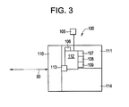
- Embodiments are implemented via a module 100 connected to a respective energy consuming device 120, as schematically illustrated, for example, in FIG. 3 .
- the system 100 uses an ambient light sensor 105 to determine when it is morning, such as by light exceeding a predefined level. Responsive to a determination that it is morning, the module 100 puts and/or keeps the energy consuming device 120 in a reduced operational or energy-saving or peak mode for a predetermined period of time.
- the light sensor 105 and counter 106 are included in the module 100 or separately on the energy consuming device 120.
- the ambient light sensor 105 can be used for dimming on-board lights when light is present around the device to reduce energy consumption, such as by limiting lighting energy use to a predefined level, particularly during a peak demand state.
- the energy consuming device 120 is itself a lamp or lighting system
- the light sensor 105 provides information used to control or simply controls the energy consumption of the device 120.
- the light sensor 105 can confirm that a lamp or lighting system is emitting an amount of light commensurate with a setting, such as a predefined light output level or and energy consumption rate of the lamp or lighting system.
- An embodiment further incorporates a counter or timer 106 so that when light is detected for a predefined period the energy consuming device is placed in an energy saving operational mode.
- the module 100 can include a module main controller 111 that includes logic circuitry that receives a signal from the light sensor 105 and is connected to the counter or timer 106 so that the module main controller triggers an energy saving operational mode of the energy consuming device when detected light exceeds a predefined level for a predefined period of time.
- the energy saving or reduced operational mode could start three hours after it is determined morning starts and be maintained until twelve hours after morning starts.
- the counter 106 also allows the module 100 to know that the room has been dark for a predetermined number of hours so that normal operation of the energy consuming device 120 can be restored.
- the module main controller 111 includes a computer processor 112 executing computer executable code read from a module computer readable storage medium 109 to make a determination of when an energy saving operational mode should be employed by the energy consuming device 120.
- the determination in an embodiment is based on the signal from the light sensor 105 and the counter or timer 106.
- the module main controller 111 of an embodiment includes a clock 107, a calendar 108, and information stored on the computer readable storage medium109 about when the day starts based on a calendar.
- the module 100 includes a communications interface 110, a module main controller 111, and a port 113, such as a communications port, with which the module main controller 111 receives information regarding the operational state of the energy consuming device 120.
- a module user interface 114 is also provided in an embodiment and can take the form of a simple button or switch interface, a touch panel interface, and/or advantageously employs a graphical user interface via a display 115 of the module 100.
- the user interface 114 allows user input to the module main controller 111, such as, but not limited to, commanding initiation of a particular operational mode of the energy consuming device 120, providing information about the environment in which the energy consuming device 120 is installed, or initiating data transfer from a removable or remote computer readable storage medium.
- the user interface 114 in an embodiment allows the user to override energy saving operational modes if the user so desires.
- the module user interface 114 selectively provides energy saving tips, information regarding energy usage, including estimates of energy usage for various operational changes, an indicator during peak or reduced operation mode, and/or other information in an embodiment, and can include device-specific information such as, for example, a counter to illustrate the energy impact of door opening on a refrigerator.
- the module main controller 111 determines what operational mode the energy consuming device 120 should employ based on user-supplied information, pre-loaded information, information supplied from remote sources via communications systems, time of day, date, and user commands and imposes the determination the energy consuming device 120 accordingly.
- the module 100 is directly connected to various components of the energy consuming device 120 and directly imposes the determination of operational mode by directly controlling the components.
- the module 100 can be built into a refrigerator/freezer and can operate the compressor(s), fan(s), and light(s) of the refrigerator/freezer in accordance with the operational mode the module main controller 111 determines should be employed.
- the module main controller 111 interacts with a controller 201 of the energy consuming device to impose the operational mode.
- the module 100 can be connected to a "smart" refrigerator/freezer, such as as an after-market device, and can instruct a controller 201 of the device to implement operational modes already incorporated into the device controller 201.
- the module 100 can be added after the energy consuming device 120 is installed in a facility, such as an externally mounted module at the wall electrical receptacle or anywhere outside or on the energy consuming device 120, or can be installed as part of assembly or manufacture, such as an integral module mounted inside the energy consuming device 120.
- Power for the module 100 can be supplied by the device 120, via a separate power supply, and/or with batteries, such as rechargeable batteries set to charge during normal operational modes of the energy consuming device 120 or ordinary batteries, such as alkaline batteries.
- the module 100 is continuously powered, while in other embodiments, the device 120 turns the module 100 off until a decision about power usage must be made, eliminating the standby power draw of the module 100.
- the module 100 in an embodiment includes a low power or hibernation mode in which the module 100 draws only enough power to enable it to monitor for a call from the energy consuming device 120 and come to a full power mode. In an embodiment in which the module 100 is powered separately, the device 120 goes to a low energy state or completely off while the module 100 continues to monitor the environment.
- the module main controller 111 communicates directly with a meter 11 or an external party 10, such as a utility company, via the port 113 and a communications network 50 to obtain information, such as an operating state of the utility, rate schedules, and/or subscription information and to determine the operational state of each associated energy consuming device 120 to employ.
- the module main controller 111 can obtain a demand state of an electric utility company to determine whether the company is operating at peak demand or at off-peak demand to determine how and/or whether the energy consuming device 120 should be operated.
- a utility meter 11 provides the information to the module main controller 111 as opposed to the module main controller 111 communicating with the external party 10 directly.
- the module 100 of an embodiment provides an interface between the external party 10 and the energy consuming device 120 that remains the same regardless of the type of device to which the module 100 is connected.
- the external party 10 can talk to virtually any energy consuming device without needing to know what kind of device it is, and the module 100 interprets what the external party 10 sends and instructs the energy consuming device 120 to which it is connected in terms it can understand.
- the module 100 can be made with different editions to accommodate company or regional variations and/or to include equipment and/or software necessary to communicate with multiple utilities in multiple formats and/or multiple communication protocols so that additional communications equipment and/or software need not be installed at or after installation.
- the module 100 in an embodiment such as that illustrated, for example, in FIG. 4 , is responsive to a facility energy management system 200.
- a system 200 includes a system controller 201 that includes a computer processor 202 that executes computer executable instructions it reads from a system computer readable storage medium 203.
- the system controller 201 communicates with the module 100, such as via a system communications port 204 and/or the port 113, and/or other similar modules in a facility via an internal communications network 51.
- the system controller 201 in an embodiment communicates with an external party 10, such as a utility company, via an external communications network 52 to obtain information, such as an operating state of the utility, a limit to be imposed on the facility, rate schedules, and/or subscription information for the facility, such as from a demand server 12 operated by the utility or a third party.
- the system controller 201 can obtain a demand state of an electric utility company to determine whether the company is operating at peak demand or at off-peak demand to determine how and/or which energy consuming devices in the facility should be operated.
- a utility meter 11 provides the information to the system controller 201 as opposed to the system controller 201 communicating with the utility directly.
- the system controller 201 passes through information and/or makes determinations of operational modes itself and sends instructions to the module 100.
- the module 100 of an embodiment using a system 200 provides an interface between the system controller 201 and the energy consuming device 120 that remains the same regardless of the type of device to which it is connected.
- the same system controller 201 can talk to virtually any energy consuming device without needing to know what kind of device it is, and the module 100 interprets what the system controller 201 sends and instructs the energy consuming device 120 to which it is connected in terms it can understand.
- the module 100 can be made to receive the same information or signals from the system controller 201 and the system controller 201 can be made with different editions to accommodate company or regional variations.
- system controller 201 and/or the module main controller 111 is configured to receive multiple signals to accommodate multiple inputs from several utility companies employing varying communication protocols.
- system controller 201 in an embodiment includes equipment and/or software necessary to communicate with multiple utilities in multiple formats and/or multiple communication protocols so that additional communications equipment and/or software need not be installed at or after installation.
- the module 100 receives signals, such as instruction signals, from the external party 10 and/or the system controller 201 via the communication interface 110, processes the signals, and determines which operational mode to employ in accordance with the signals and superceding the signals responsive to an override command having been received by the module 100.
- the module main controller 111 prevents execution of override instructions or instruction signals received from the user or from the system controller 201, though in an alternative embodiment, the module main controller 111 executes but logs any override instructions and notifies the external party 10 and/or system controller 201 of the override(s).
- the system controller 201 instructs the module main controller 111 that overrides are not permitted and the module main controller 111 refuses to execute override instructions attempted via the module user interface 114.
- overrides are simply logged and reported by the system controller 201 and/or the module main controller 111.
- the module main controller 111 of embodiments receives information via the communications network 50, which can include computer networks, the internet, power line transmission/reception, electromagnetic radiation broadcast/reception, telephone networks, a Local Area Network, and other suitable forms as may be appropriate for a particular application.
- the communications network 50 can include computer networks, the internet, power line transmission/reception, electromagnetic radiation broadcast/reception, telephone networks, a Local Area Network, and other suitable forms as may be appropriate for a particular application.
- information regarding a demand state, demand limit, and/or operational mode to be employed is conveyed using tones.
- a tone generator 301 responsive to a rate charged for energy generates a tone, such as a continuous tone, indicative of a respective rate.
- the tone is transmitted via a radio frequency transmitter 302, such as a transmitter using a frequency in the FM band, on a carrier frequency. While FM band radio frequencies are identified as used in an embodiment, it should be clear that any other suitable radio frequencies or other frequency ranges of electromagnetic radiation could be employed.
- the module 100 in such an embodiment includes a receiver 303 that receives the carrier frequency and decodes the tone or sends the received signal to the module main controller 111 for decoding.
- the module 100 then instructs the energy consuming device 120 to employ an operational state in accordance with the received tone.
- the tone generator in another embodiment generates a combination of tones to convey information, and another embodiment sends tones via hard wire connections. For example, when passing rate information such as rate 1, 2, 3, or 4, using different tones for respective rates is sufficient. Alternatively, assigning a binary number to a given tone allows more sophisticated messaging using binary coding with multiple tones, the module interpreting the coded messages and instructing the energy consuming device 120 as appropriate.
- the communications network 50 employs a radio frequency identification (RFID) tag system 400 with a RFID master 401 as part of or responsive to the external party 10, the system controller 201, as seen in FIGS. 4 and 6 .
- RFID radio frequency identification
- Each module 100 then includes or is responsive to a RFID tag 402, also referred to as a "slave device,” with its own respective resonant frequency unique within at least the range of the RFID master device 401.
- the RFID tag 402 passes signals received to the module main controller 111.
- the RFID master 401 sends the change or a command to the energy consuming device 120 by resonating at the respective resonant frequency of the energy consuming device 120.
- the RFID tag 402 is an active RFID tag that can store data transmitted by the RFID master 401 via a pulse of energy at a resonant frequency of the RFID tag 402. Additionally, embodiments employ tags with binary or other codes unique within the system to enable the RFID master device to instruct the slave devices.
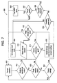
- an embodiment includes normal operation of an energy consuming device 120 (block 601) and checking to see if the energy consuming device 120 is or should be in a reduced operational mode (block 602). If not, then normal operation continues (block 601). If so, then the method includes checking to see if there is a peak demand state (block 603) and checking device priority responsive to a peak demand state (block 604). If there is no peak demand state, or if there is a peak demand state and the energy consuming device 120 has a high device priority, then normal operation continues (block 601). If there is a peak demand state and the device priority is low, then the method includes checking to see if an override command or instruction has been received (block 605).
- the method includes checking to see if overrides are allowed (block 606). If overrides are allowed, then the method proceeds by instructing the energy using device(s) to employ normal operational mode (block 601). If overrides are not allowed, then the method includes checking to see whether overrides are logged and/or reported or forbidden (block 607). If overrides are logged and/or reported, then the method includes logging and/or reporting the override (block 608) and instructing the energy using device(s) to employ normal operational mode (block 601).
- the method proceeds by setting an energy need level (block 609), reading any internal sensors (block 610), and determining whether the energy consuming device 120 is maintaining a goal or target performance (block 611). If the energy consuming device 120 is maintaining the goal or target performance, then the method checks to see whether the peak demand state is over (block 612) and, if the peak demand state continues, returns to reading internal sensors (block 610) and/or checking the performance of the energy consuming device 120 (block 611). If the peak demand state is over, then normal operation resumes (block 601).
- the energy need level is adjusted (block 613) based on, for example, sensor readings, and the method proceeds to block 612 to check whether the peak demand state is over.
- the portion of the method 600 in an embodiment is implemented and performed in the system controller 201, but in another embodiment is implemented and performed in the module main controller 111, and in a third embodiment is spread across both the system controller101 and the module main controller 111.
- a method according to embodiments is realized via, and a system according to embodiments includes, computer-implemented processes and apparatus for practicing such processes, such as the system controller 201 and/or the module main controller 111.
- an embodiment includes a computer program product including computer code, such as object code, source code, or executable code, on tangible media, such as magnetic media (floppy diskettes, hard disc drives, tape, etc.), optical media (compact discs, digital versatile/video discs, magneto-optical discs, etc.), random access memory (RAM), read only memory (ROM), flash ROM, erasable programmable read only memory (EPROM), or any other computer readable storage medium on which the computer program code is stored and with which the computer program code can be loaded into and executed by a computer.
- computer code such as object code, source code, or executable code
- tangible media such as magnetic media (floppy diskettes, hard disc drives, tape, etc.), optical media (compact discs, digital versatile/video discs, magneto-optical discs, etc.
- the computer When the computer executes the computer program code, it becomes an apparatus for practicing the invention, and on a general purpose microprocessor, specific logic circuits are created by configuration of the microprocessor with computer code segments.
- a technical effect of the executable instructions is to implement energy consumption reduction and/or optimization in an energy consuming device, a facility with at least one energy consuming device, and/or an energy supply distribution system.
- the computer program code is written in computer instructions executable by the controller, such as in the form of software encoded in any programming language.
- suitable programming languages include, but are not limited to, assembly language, VHDL (Verilog Hardware Description Language), Very High Speed IC Hardware Description Language (VHSIC HDL), FORTRAN (Formula Translation), C, C++, C#, Java, ALGOL (Algorithmic Language), BASIC (Beginner All-Purpose Symbolic Instruction Code), APL (A Programming Language), ActiveX, HTML (HyperText Markup Language), XML (extensible Markup Language), and any combination or derivative of one or more of these.
Landscapes
- Engineering & Computer Science (AREA)
- Power Engineering (AREA)
- Supply And Distribution Of Alternating Current (AREA)
- Remote Monitoring And Control Of Power-Distribution Networks (AREA)
- Management, Administration, Business Operations System, And Electronic Commerce (AREA)
Applications Claiming Priority (1)
| Application Number | Priority Date | Filing Date | Title |
|---|---|---|---|
| US12/388,112 US20100207728A1 (en) | 2009-02-18 | 2009-02-18 | Energy management |
Publications (2)
| Publication Number | Publication Date |
|---|---|
| EP2221756A2 true EP2221756A2 (de) | 2010-08-25 |
| EP2221756A3 EP2221756A3 (de) | 2012-06-27 |
Family
ID=42035986
Family Applications (1)
| Application Number | Title | Priority Date | Filing Date |
|---|---|---|---|
| EP10153695A Ceased EP2221756A3 (de) | 2009-02-18 | 2010-02-16 | Energieverwaltung |
Country Status (4)
| Country | Link |
|---|---|
| US (1) | US20100207728A1 (de) |
| EP (1) | EP2221756A3 (de) |
| JP (1) | JP2010193705A (de) |
| CN (1) | CN101887244A (de) |
Cited By (4)
| Publication number | Priority date | Publication date | Assignee | Title |
|---|---|---|---|---|
| CN103814495A (zh) * | 2011-09-22 | 2014-05-21 | 松下电器产业株式会社 | 电力调整装置以及电力调整方法 |
| US9513613B2 (en) | 2010-06-22 | 2016-12-06 | Lg Electronics Inc. | Method for controlling component for network system |
| EP2444765A3 (de) * | 2010-10-20 | 2017-05-03 | Liebherr-Hausgeräte Ochsenhausen GmbH | System umfassend wenigstens ein Kühl-und/oder Gefriergerät |
| FR3060819A1 (fr) * | 2016-12-19 | 2018-06-22 | Electricite De France | Coordination de gestion de consommation d'energie electrique |
Families Citing this family (47)
| Publication number | Priority date | Publication date | Assignee | Title |
|---|---|---|---|---|
| US8560476B2 (en) | 2003-08-26 | 2013-10-15 | The Trustees Of Columbia University In The City Of New York | Martingale control of production for optimal profitability of oil and gas fields |
| WO2009117742A1 (en) * | 2008-03-21 | 2009-09-24 | The Trustees Of Columbia University In The City Of New York | Methods and systems of determining the effectiveness of capital improvement projects |
| WO2009117741A1 (en) * | 2008-03-21 | 2009-09-24 | The Trustees Of Columbia University In The City Of New York | Decision support control centers |
| WO2010096783A1 (en) | 2009-02-20 | 2010-08-26 | The Trustees Of Columbia University In The City Of New York | Dynamic contingency avoidance and mitigation system |
| US8725625B2 (en) | 2009-05-28 | 2014-05-13 | The Trustees Of Columbia University In The City Of New York | Capital asset planning system |
| US8600556B2 (en) * | 2009-06-22 | 2013-12-03 | Johnson Controls Technology Company | Smart building manager |
| DE102009027800A1 (de) * | 2009-07-17 | 2011-01-27 | BSH Bosch und Siemens Hausgeräte GmbH | Haushaltsgerät mit einer Kommunikationseinrichtung, Gerätesystem und Verfahren zum Betreiben eines Haushaltsgeräts |
| US8855830B2 (en) | 2009-08-21 | 2014-10-07 | Allure Energy, Inc. | Energy management system and method |
| US8498749B2 (en) | 2009-08-21 | 2013-07-30 | Allure Energy, Inc. | Method for zone based energy management system with scalable map interface |
| US9838255B2 (en) | 2009-08-21 | 2017-12-05 | Samsung Electronics Co., Ltd. | Mobile demand response energy management system with proximity control |
| US9209652B2 (en) | 2009-08-21 | 2015-12-08 | Allure Energy, Inc. | Mobile device with scalable map interface for zone based energy management |
| US20110264276A1 (en) * | 2009-10-30 | 2011-10-27 | Rudin Management Co. Inc. | Interconnected electrical network and building management system and method of operation |
| KR101678439B1 (ko) * | 2010-09-17 | 2016-12-06 | 엘지전자 주식회사 | 이동식 전력공급장치 |
| EP2539861A4 (de) | 2010-02-24 | 2013-08-07 | Univ Columbia | Metrisches überwachungs- und finanzvalidierungssystem zur verfolgung der leistung bei der verbesserung einer infrastruktur |
| JP5520118B2 (ja) * | 2010-04-02 | 2014-06-11 | パナソニック株式会社 | 機器制御システム |
| KR20110119324A (ko) * | 2010-04-27 | 2011-11-02 | 엘지전자 주식회사 | 스마트 제어 디바이스 |
| US8583405B2 (en) | 2010-05-11 | 2013-11-12 | Maggie Chow | Contingency analysis information for utility service network |
| ES2535954T3 (es) * | 2010-07-16 | 2015-05-19 | Lg Electronics Inc. | Componente para un sistema de red |
| EP2593844A4 (de) | 2010-07-16 | 2017-05-31 | The Trustees of Columbia University in the City of New York | Maschinelles lernen für stromnetze |
| US8718798B2 (en) * | 2010-11-09 | 2014-05-06 | General Electric Company | Gateway mirroring of metering data between zigbee networks |
| US20120047921A1 (en) | 2010-11-22 | 2012-03-01 | General Electric Company | Dsm enabling of electro mechanically controlled refrigeration systems |
| US8504216B2 (en) * | 2010-11-22 | 2013-08-06 | General Electric Company | DSM enabling of electro mechanically controlled refrigeration systems |
| KR101817355B1 (ko) * | 2011-01-31 | 2018-01-11 | 삼성전자주식회사 | 스마트 전자제품의 전력 관리 방법 및 장치 |
| US8364326B2 (en) * | 2011-02-22 | 2013-01-29 | Asoka Usa Corporation | Set of sensor units for communication enabled for streaming media delivery with monitoring and control of power usage of connected appliances |
| US8755946B2 (en) * | 2011-02-22 | 2014-06-17 | Asoka Usa Corporation | Method and apparatus for using PLC-based sensor units for communication and streaming media delivery, and for monitoring and control of power usage of connected appliances |
| US9736789B2 (en) | 2011-02-22 | 2017-08-15 | Asoka Usa Corporation | Power line communication-based local hotspot with wireless power control capability |
| US8644166B2 (en) | 2011-06-03 | 2014-02-04 | Asoka Usa Corporation | Sensor having an integrated Zigbee® device for communication with Zigbee® enabled appliances to control and monitor Zigbee® enabled appliances |
| US9257842B2 (en) | 2011-02-22 | 2016-02-09 | Asoka Usa Corporation | Set-top-box having a built-in master node that provides an external interface for communication and control in a power-line-based residential communication system |
| KR101158231B1 (ko) * | 2011-04-29 | 2012-06-19 | 삼성전기주식회사 | 대기전력 절감형 전력모니터링 장치, 전기 부하기기 및 전력모니터링 방법 |
| US10935948B2 (en) | 2011-08-02 | 2021-03-02 | Synaptic Power Inc. | System and method for managing interactions between a plurality of devices |
| CA2877759C (en) | 2011-08-02 | 2015-11-10 | Charles Morin | A system and a method of controlling a plurality of devices |
| EP2751955B1 (de) | 2011-08-30 | 2019-11-13 | Samsung Electronics Co., Ltd. | Resourcenmanager und verfahren zur übertragung von ressourcenverwaltungsinformationen für intelligente energie- und medienressourcen |
| US20120095605A1 (en) * | 2011-09-17 | 2012-04-19 | Tran Bao Q | Smart building systems and methods |
| JP5752064B2 (ja) * | 2012-02-03 | 2015-07-22 | 三菱電機株式会社 | 冷凍サイクル装置及び冷凍サイクル装置の運転管理システム |
| US9010133B2 (en) | 2012-06-20 | 2015-04-21 | Whirlpool Corporation | On-line energy consumption optimization adaptive to environmental condition |
| GB2506401A (en) * | 2012-09-28 | 2014-04-02 | Ibm | Method for allocating electrical energy in a smart grid |
| US9716530B2 (en) | 2013-01-07 | 2017-07-25 | Samsung Electronics Co., Ltd. | Home automation using near field communication |
| US10063499B2 (en) | 2013-03-07 | 2018-08-28 | Samsung Electronics Co., Ltd. | Non-cloud based communication platform for an environment control system |
| JP6124642B2 (ja) * | 2013-03-26 | 2017-05-10 | 三菱電機株式会社 | 電力管理システム及び冷蔵庫 |
| CN106464551A (zh) | 2014-01-06 | 2017-02-22 | 魅力能源公司 | 一种使用网络装置和基于遥感的信息来协调环境的系统、装置和设备 |
| US10135628B2 (en) | 2014-01-06 | 2018-11-20 | Samsung Electronics Co., Ltd. | System, device, and apparatus for coordinating environments using network devices and remote sensory information |
| US10386800B2 (en) | 2015-02-24 | 2019-08-20 | Siemens Industry, Inc. | Variable air volume modeling for an HVAC system |
| US11214157B2 (en) * | 2015-12-30 | 2022-01-04 | Proterra Inc. | Electric vehicle charging to reduce utility cost |
| KR101749457B1 (ko) * | 2016-05-24 | 2017-07-13 | 주식회사 신일이앤씨 | 이미지 센서를 이용한 공장 에너지 관리 시스템 |
| KR101749456B1 (ko) * | 2016-05-24 | 2017-06-26 | 주식회사 신일이앤씨 | 공장 에너지 관리 시스템 |
| WO2022103920A1 (en) * | 2020-11-13 | 2022-05-19 | Full Speed Automation, Inc. | System and apparatus for optimizing the energy consumption of manufacturing equipment |
| US12353268B2 (en) * | 2023-08-22 | 2025-07-08 | The Boeing Company | High-energy management system |
Family Cites Families (106)
| Publication number | Priority date | Publication date | Assignee | Title |
|---|---|---|---|---|
| US548578A (en) * | 1895-10-22 | Animal-trap | ||
| US2545054A (en) * | 1946-02-25 | 1951-03-13 | Wilbur E Stitz | Refrigerator control |
| US3683343A (en) * | 1970-07-27 | 1972-08-08 | Stephen Feldman | Demand metering system for electric energy |
| US4048812A (en) * | 1976-02-17 | 1977-09-20 | Thomason Harry E | Solar-energy conserving |
| US4190756A (en) * | 1976-03-29 | 1980-02-26 | Amana Refrigeration, Inc. | Digitally programmed microwave cooker |
| US4167786A (en) * | 1978-01-24 | 1979-09-11 | General Electric Company | Load control processor |
| US4216658A (en) * | 1978-05-11 | 1980-08-12 | Baker Ralph N Iii | Refrigeration means and methods |
| US4247786A (en) * | 1979-03-15 | 1981-01-27 | Cyborex Laboratories, Inc. | Energy management method using utility-generated signals |
| US4454509A (en) * | 1980-02-27 | 1984-06-12 | Regency Electronics, Inc. | Apparatus for addressably controlling remote units |
| US4362970A (en) * | 1980-09-08 | 1982-12-07 | Grady John K | Energy conserving electrical power control circuit |
| US4718403A (en) * | 1985-10-11 | 1988-01-12 | Exemplar, Inc. | Control for water heater system |
| US4659943A (en) * | 1986-03-19 | 1987-04-21 | Virant Robert L | Peak demand limiter |
| US4731547A (en) * | 1986-12-12 | 1988-03-15 | Caterpillar Inc. | Peak power shaving apparatus and method |
| US4998024A (en) * | 1988-04-01 | 1991-03-05 | Vaughn Manufacturing Corporation | Energy controlling system for time shifting electric power use |
| US5040724A (en) * | 1989-12-11 | 1991-08-20 | Eaton Corporation | Electronic control system for an oven |
| US5479157A (en) * | 1990-01-19 | 1995-12-26 | Prince Corporation | Remote vehicle programming system |
| US5183998A (en) * | 1990-05-30 | 1993-02-02 | Mr. Coffee Inc. | Apparatus and method for heating water for infusion and the like |
| US5137041A (en) * | 1990-09-21 | 1992-08-11 | Glastender, Inc. | Dishwasher with fill water control |
| US5495551A (en) * | 1991-07-12 | 1996-02-27 | Electric Power Research Institute, Inc. | Fast recovery circuit for heat pump water heater |
| US5220807A (en) * | 1991-08-27 | 1993-06-22 | Davis Energy Group, Inc. | Combined refrigerator water heater |
| US5481140A (en) * | 1992-03-10 | 1996-01-02 | Mitsubishi Denki Kabushiki Kaisha | Demand control apparatus and power distribution control system |
| EP0808012A1 (de) * | 1992-07-03 | 1997-11-19 | EURO CP s.a.r.l. | Verfahren zur Steuerung der Stromverbrauchzählung in einer örtlichen Netzwerkanordnung |
| US5479558A (en) * | 1993-08-30 | 1995-12-26 | White, Jr.; James A. | Flow-through tankless water heater with flow switch and heater control system |
| US5462225A (en) * | 1994-02-04 | 1995-10-31 | Scientific-Atlanta, Inc. | Apparatus and method for controlling distribution of electrical energy to a space conditioning load |
| US5635895A (en) * | 1994-02-14 | 1997-06-03 | Murr; William C. | Remote power cost display system |
| US5451843A (en) * | 1994-04-22 | 1995-09-19 | Ruud Lighting, Inc. | Apparatus and method for providing bilevel illumination |
| US5505377A (en) * | 1994-05-18 | 1996-04-09 | Micro Weiss Electronics, Inc. | Automatic wall thermostat |
| US5574979A (en) * | 1994-06-03 | 1996-11-12 | Norand Corporation | Periodic interference avoidance in a wireless radio frequency communication system |
| US5504306A (en) * | 1994-07-25 | 1996-04-02 | Chronomite Laboratories, Inc. | Microprocessor controlled tankless water heater system |
| US5706191A (en) * | 1995-01-19 | 1998-01-06 | Gas Research Institute | Appliance interface apparatus and automated residence management system |
| US6018150A (en) * | 1995-03-23 | 2000-01-25 | Tridelta Industries, Inc. | Method of heating a medium to a desired temperature |
| US6380866B1 (en) * | 1995-06-08 | 2002-04-30 | Lucent Technologies Inc. | System and apparatus for controlling an appliance situated within a premises |
| US5581132A (en) * | 1995-08-04 | 1996-12-03 | Chadwick; Jon D. | Peak demand limiter and sequencer |
| AU7016396A (en) * | 1995-10-10 | 1997-04-30 | Donald Kuhnel | Fluid heater with improved heating elements controller |
| US5816491A (en) * | 1996-03-15 | 1998-10-06 | Arnold D. Berkeley | Method and apparatus for conserving peak load fuel consumption and for measuring and recording fuel consumption |
| US5874902A (en) * | 1996-07-29 | 1999-02-23 | International Business Machines Corporation | Radio frequency identification transponder with electronic circuit enabling/disabling capability |
| US5956462A (en) * | 1996-09-26 | 1999-09-21 | Aquabeat Pty Ltd. | Domestic electric energy control |
| US5883802A (en) * | 1996-12-27 | 1999-03-16 | Alliance Laundry Systems Llc | Energy usage controller for an appliance |
| JPH10282161A (ja) * | 1997-04-09 | 1998-10-23 | Matsushita Electric Ind Co Ltd | 消費電力監視システム |
| US5867017A (en) * | 1997-04-21 | 1999-02-02 | Motorola Inc. | Energy control system with remote switching |
| US5880536A (en) * | 1997-05-14 | 1999-03-09 | Io Limited Partnership, Llp | Customer side power management system including auxiliary fuel cell for reducing potential peak load upon utilities and providing electric power for auxiliary equipment |
| US6080971A (en) * | 1997-05-22 | 2000-06-27 | David Seitz | Fluid heater with improved heating elements controller |
| US5926776A (en) * | 1997-06-04 | 1999-07-20 | Gas Research Institute | Smart thermostat having a transceiver interface |
| US6185483B1 (en) * | 1998-01-27 | 2001-02-06 | Johnson Controls, Inc. | Real-time pricing controller of an energy storage medium |
| JP3498239B2 (ja) * | 1998-03-25 | 2004-02-16 | 三菱電機株式会社 | ショーケースシステム |
| US6122603A (en) * | 1998-05-29 | 2000-09-19 | Powerweb, Inc. | Multi-utility energy control system with dashboard |
| US6026651A (en) * | 1998-07-21 | 2000-02-22 | Heat Timer Corporation | Remote controlled defrost sequencer |
| US6244831B1 (en) * | 1998-08-12 | 2001-06-12 | Kawasaki Jukogyo Kabushiki Kaisha | Control device for variable displacement pump |
| US6359270B1 (en) * | 1998-09-04 | 2002-03-19 | Ncr Corporation | Communications module mounting for domestic appliance |
| IT1304664B1 (it) * | 1998-09-30 | 2001-03-28 | Merloni Elettrodomestici Spa | Sistema per la programmazione di un apparato elettrodomestico acontrollo elettronico. |
| US6898942B2 (en) * | 1998-10-28 | 2005-05-31 | Usa Technologies, Inc. | Method and apparatus for conserving power consumed by a refrigerated appliance utilizing dispensing event data signals |
| US6118099A (en) * | 1998-11-12 | 2000-09-12 | Daimlerchrysler Corporation | Controller for heating in reversible air conditioning and heat pump HVAC system for electric vehicles |
| US6179213B1 (en) * | 1999-02-09 | 2001-01-30 | Energy Rest, Inc. | Universal accessory for timing and cycling heat, ventilation and air conditioning energy consumption and distribution systems |
| JP2000244989A (ja) * | 1999-02-19 | 2000-09-08 | Sharp Corp | 双方向リモコン制御システム |
| EP1161853A1 (de) * | 1999-03-11 | 2001-12-12 | Power Circuit Innovations, Inc | Netzanschliessbarer leistungsregler |
| US6539213B1 (en) * | 1999-06-14 | 2003-03-25 | Time Domain Corporation | System and method for impulse radio power control |
| US6229433B1 (en) * | 1999-07-30 | 2001-05-08 | X-10 Ltd. | Appliance control |
| US20040024483A1 (en) * | 1999-12-23 | 2004-02-05 | Holcombe Bradford L. | Controlling utility consumption |
| US6934862B2 (en) * | 2000-01-07 | 2005-08-23 | Robertshaw Controls Company | Appliance retrofit monitoring device with a memory storing an electronic signature |
| US6489597B1 (en) * | 2000-01-10 | 2002-12-03 | General Electric Company | Range surface heating unit relay power switching control |
| US20010048361A1 (en) * | 2000-06-01 | 2001-12-06 | Mays Wesley M. | Method and apparatus for providing interchangeability of RFID devices |
| US6891478B2 (en) * | 2000-06-09 | 2005-05-10 | Jay Warren Gardner | Methods and apparatus for controlling electric appliances during reduced power conditions |
| JP4547776B2 (ja) * | 2000-06-19 | 2010-09-22 | ダイキン工業株式会社 | 電気機器のデマンド制御システム、デマンド制御方法、デマンド制御管理装置及びデマンド制御管理方法 |
| JP4042310B2 (ja) * | 2000-07-10 | 2008-02-06 | 富士電機リテイルシステムズ株式会社 | 店舗内機器の消費電力制御方法 |
| EP1186695B1 (de) * | 2000-09-12 | 2012-05-30 | Kabushiki Kaisha Toshiba | Fernsteuerungssystem für Wäschegerät |
| US6782706B2 (en) * | 2000-12-22 | 2004-08-31 | General Electric Company | Refrigerator—electronics architecture |
| KR100653056B1 (ko) * | 2001-03-09 | 2006-12-01 | 삼성전자주식회사 | 전자렌지 및 그 절전모드 제어방법 |
| US6828695B1 (en) * | 2001-04-09 | 2004-12-07 | Rick L. Hansen | System, apparatus and method for energy distribution monitoring and control and information transmission |
| US20020198629A1 (en) * | 2001-04-27 | 2002-12-26 | Enerwise Global Technologies, Inc. | Computerized utility cost estimation method and system |
| US20020175806A1 (en) * | 2001-05-25 | 2002-11-28 | Marneweck Willem J. | Electronic tag binary selection method |
| US7009493B2 (en) * | 2001-06-22 | 2006-03-07 | Matsushita Electric Works, Ltd. | Electronic device with paging for energy curtailment and code generation for manual verification of curtailment |
| JP2003088004A (ja) * | 2001-07-02 | 2003-03-20 | Matsushita Electric Ind Co Ltd | 電力管理装置 |
| US20030036820A1 (en) * | 2001-08-16 | 2003-02-20 | International Business Machines Corporation | Method for optimizing energy consumption and cost |
| KR100409008B1 (ko) * | 2001-08-24 | 2003-12-06 | 엘지전자 주식회사 | 가전기기 제어데이터 전송시스템 및 그 방법 |
| KR100381174B1 (ko) * | 2001-09-03 | 2003-04-18 | 엘지전자 주식회사 | 가전기기 데이터 전송시스템 |
| US7110832B2 (en) * | 2002-03-22 | 2006-09-19 | Whirlpool Corporation | Energy management system for an appliance |
| US6704401B2 (en) * | 2002-03-22 | 2004-03-09 | Hewlett-Packard Development Company, L.P. | System of and method for configuring an automatic appliance |
| CN1656661A (zh) * | 2002-03-28 | 2005-08-17 | 罗伯绍控制器公司 | 能源管理系统和方法 |
| US6817195B2 (en) * | 2002-03-29 | 2004-11-16 | General Electric Company | Reduced energy refrigerator defrost method and apparatus |
| US7049976B2 (en) * | 2002-04-15 | 2006-05-23 | Hunt Power, L.P. | User-installable power consumption monitoring system |
| EP1372238B1 (de) * | 2002-06-13 | 2018-06-06 | Whirlpool Corporation | Gesamtsystem für Hausenergiemanagement |
| US20040034484A1 (en) * | 2002-06-24 | 2004-02-19 | Solomita Michael V. | Demand-response energy management system |
| US6943321B2 (en) * | 2002-08-30 | 2005-09-13 | Wolf Appliance Company, Llc | Convection oven with forced airflow circulation zones |
| US6806446B1 (en) * | 2002-10-04 | 2004-10-19 | Stephen D. Neale | Power management controls for electric appliances |
| US6961642B2 (en) * | 2002-11-15 | 2005-11-01 | Whirlpool Corporation | System and method for reducing an instantaneous load in an appliance |
| KR20040044707A (ko) * | 2002-11-21 | 2004-05-31 | 삼성전자주식회사 | 전자레인지용 마그네트론 |
| JP2004178938A (ja) * | 2002-11-26 | 2004-06-24 | Matsushita Electric Works Ltd | 照明制御システムおよびマネジメントシステム |
| US7246395B2 (en) * | 2002-12-09 | 2007-07-24 | General Electric Company | Washer/dryer graphical user interface |
| US8567091B2 (en) * | 2002-12-24 | 2013-10-29 | Lg Electronics Inc | Automatic dryer control based on load information |
| US6694927B1 (en) * | 2003-02-18 | 2004-02-24 | Honeywell International Inc. | Cold water draw bypass valve and variable firing boiler control |
| US7041940B2 (en) * | 2003-03-28 | 2006-05-09 | General Electric Company | Power management systems and methods |
| US7010363B2 (en) * | 2003-06-13 | 2006-03-07 | Battelle Memorial Institute | Electrical appliance energy consumption control methods and electrical energy consumption systems |
| EP1489719A3 (de) * | 2003-06-20 | 2007-05-02 | Matsushita Electric Industrial Co., Ltd. | Energievewaltungssystem, Energieverwaltungsverfahren und Einheit zur Verfügungsstellung von Informationen über energiesparende empfohlene Einrichtung |
| US7155912B2 (en) * | 2003-10-27 | 2007-01-02 | Enis Ben M | Method and apparatus for storing and using energy to reduce the end-user cost of energy |
| US7113075B2 (en) * | 2003-12-23 | 2006-09-26 | General Electric Company | Power supply methods and apparatus |
| US7317404B2 (en) * | 2004-01-14 | 2008-01-08 | Itron, Inc. | Method and apparatus for collecting and displaying consumption data from a meter reading system |
| US7379791B2 (en) * | 2004-08-03 | 2008-05-27 | Uscl Corporation | Integrated metrology systems and information and control apparatus for interaction with integrated metrology systems |
| JP4335126B2 (ja) * | 2004-12-10 | 2009-09-30 | 日本電信電話株式会社 | サーバ装置、電化装置、無線発信装置、管理サーバ、電化装置制御システム、電力管理方法並びにコンピュータプログラム及びその記録媒体 |
| US8615332B2 (en) * | 2005-06-09 | 2013-12-24 | Whirlpool Corporation | Smart current attenuator for energy conservation in appliances |
| US7280810B2 (en) * | 2005-08-03 | 2007-10-09 | Kamilo Feher | Multimode communication system |
| JP4936713B2 (ja) * | 2005-11-29 | 2012-05-23 | 中国電力株式会社 | 電気事故情報提供システム、電気事故情報提供方法、および、電気事故情報提供プログラム |
| US7781713B2 (en) * | 2006-02-08 | 2010-08-24 | The Regents Of The University Of California | Method for calibrating a lighting control system that facilitates daylight harvesting |
| US20080177678A1 (en) * | 2007-01-24 | 2008-07-24 | Paul Di Martini | Method of communicating between a utility and its customer locations |
| WO2008100641A1 (en) * | 2007-02-16 | 2008-08-21 | Genea Energy Partners, Inc. | Building optimization system and lighting switch |
| US8145918B2 (en) * | 2007-06-28 | 2012-03-27 | International Business Machines Corporation | Monitoring system processes energy consumption |
| US8617316B2 (en) * | 2008-09-15 | 2013-12-31 | General Electric Company | Energy management of dishwasher appliance |
-
2009
- 2009-02-18 US US12/388,112 patent/US20100207728A1/en not_active Abandoned
-
2010
- 2010-02-11 CN CN2010101257293A patent/CN101887244A/zh active Pending
- 2010-02-12 JP JP2010028378A patent/JP2010193705A/ja active Pending
- 2010-02-16 EP EP10153695A patent/EP2221756A3/de not_active Ceased
Non-Patent Citations (1)
| Title |
|---|
| None |
Cited By (7)
| Publication number | Priority date | Publication date | Assignee | Title |
|---|---|---|---|---|
| US9513613B2 (en) | 2010-06-22 | 2016-12-06 | Lg Electronics Inc. | Method for controlling component for network system |
| EP2587726B1 (de) * | 2010-06-22 | 2020-02-26 | LG Electronics Inc. | Verfahren für steuerungskomponente für netzwerksystem |
| EP2444765A3 (de) * | 2010-10-20 | 2017-05-03 | Liebherr-Hausgeräte Ochsenhausen GmbH | System umfassend wenigstens ein Kühl-und/oder Gefriergerät |
| CN103814495A (zh) * | 2011-09-22 | 2014-05-21 | 松下电器产业株式会社 | 电力调整装置以及电力调整方法 |
| EP2760099A4 (de) * | 2011-09-22 | 2015-02-18 | Panasonic Corp | Stromaufbereitungsvorrichtung und stromaufbereitungsverfahren |
| CN103814495B (zh) * | 2011-09-22 | 2016-07-06 | 松下知识产权经营株式会社 | 电力调整装置以及电力调整方法 |
| FR3060819A1 (fr) * | 2016-12-19 | 2018-06-22 | Electricite De France | Coordination de gestion de consommation d'energie electrique |
Also Published As
| Publication number | Publication date |
|---|---|
| US20100207728A1 (en) | 2010-08-19 |
| JP2010193705A (ja) | 2010-09-02 |
| EP2221756A3 (de) | 2012-06-27 |
| CN101887244A (zh) | 2010-11-17 |
Similar Documents
| Publication | Publication Date | Title |
|---|---|---|
| EP2221756A2 (de) | Energieverwaltung | |
| CA2723073C (en) | Energy management of household appliances | |
| US20120109395A1 (en) | Controlling multiple smart appliances with a single communication interface |
Legal Events
| Date | Code | Title | Description |
|---|---|---|---|
| PUAI | Public reference made under article 153(3) epc to a published international application that has entered the european phase |
Free format text: ORIGINAL CODE: 0009012 |
|
| AK | Designated contracting states |
Kind code of ref document: A2 Designated state(s): AT BE BG CH CY CZ DE DK EE ES FI FR GB GR HR HU IE IS IT LI LT LU LV MC MK MT NL NO PL PT RO SE SI SK SM TR |
|
| AX | Request for extension of the european patent |
Extension state: AL BA RS |
|
| RIC1 | Information provided on ipc code assigned before grant |
Ipc: H02J 3/12 20060101ALI20120112BHEP Ipc: H02J 3/14 20060101ALI20120112BHEP Ipc: G06Q 10/00 20120101AFI20120112BHEP |
|
| PUAL | Search report despatched |
Free format text: ORIGINAL CODE: 0009013 |
|
| AK | Designated contracting states |
Kind code of ref document: A3 Designated state(s): AT BE BG CH CY CZ DE DK EE ES FI FR GB GR HR HU IE IS IT LI LT LU LV MC MK MT NL NO PL PT RO SE SI SK SM TR |
|
| AX | Request for extension of the european patent |
Extension state: AL BA RS |
|
| RIC1 | Information provided on ipc code assigned before grant |
Ipc: G06Q 10/00 20120101AFI20120518BHEP Ipc: H02J 3/14 20060101ALI20120518BHEP Ipc: H02J 3/12 20060101ALI20120518BHEP |
|
| 17P | Request for examination filed |
Effective date: 20130102 |
|
| 17Q | First examination report despatched |
Effective date: 20130415 |
|
| STAA | Information on the status of an ep patent application or granted ep patent |
Free format text: STATUS: THE APPLICATION HAS BEEN REFUSED |
|
| 18R | Application refused |
Effective date: 20150201 |