EP2223582B1 - Clé usb - Google Patents
Clé usb Download PDFInfo
- Publication number
- EP2223582B1 EP2223582B1 EP08858560A EP08858560A EP2223582B1 EP 2223582 B1 EP2223582 B1 EP 2223582B1 EP 08858560 A EP08858560 A EP 08858560A EP 08858560 A EP08858560 A EP 08858560A EP 2223582 B1 EP2223582 B1 EP 2223582B1
- Authority
- EP
- European Patent Office
- Prior art keywords
- usb stick
- housing
- pen
- usb
- cap
- Prior art date
- Legal status (The legal status is an assumption and is not a legal conclusion. Google has not performed a legal analysis and makes no representation as to the accuracy of the status listed.)
- Not-in-force
Links
- 230000007246 mechanism Effects 0.000 claims description 12
- 238000000034 method Methods 0.000 description 6
- 238000004026 adhesive bonding Methods 0.000 description 2
- 239000004809 Teflon Substances 0.000 description 1
- 229920006362 Teflon® Polymers 0.000 description 1
- 230000008878 coupling Effects 0.000 description 1
- 238000010168 coupling process Methods 0.000 description 1
- 238000005859 coupling reaction Methods 0.000 description 1
- 239000010437 gem Substances 0.000 description 1
- 229910001751 gemstone Inorganic materials 0.000 description 1
- 239000000463 material Substances 0.000 description 1
- 238000007789 sealing Methods 0.000 description 1
Images


Classifications
-
- H—ELECTRICITY
- H05—ELECTRIC TECHNIQUES NOT OTHERWISE PROVIDED FOR
- H05K—PRINTED CIRCUITS; CASINGS OR CONSTRUCTIONAL DETAILS OF ELECTRIC APPARATUS; MANUFACTURE OF ASSEMBLAGES OF ELECTRICAL COMPONENTS
- H05K5/00—Casings, cabinets or drawers for electric apparatus
- H05K5/02—Details
- H05K5/0256—Details of interchangeable modules or receptacles therefor, e.g. cartridge mechanisms
- H05K5/026—Details of interchangeable modules or receptacles therefor, e.g. cartridge mechanisms having standardized interfaces
- H05K5/0278—Details of interchangeable modules or receptacles therefor, e.g. cartridge mechanisms having standardized interfaces of USB type
-
- A—HUMAN NECESSITIES
- A44—HABERDASHERY; JEWELLERY
- A44B—BUTTONS, PINS, BUCKLES, SLIDE FASTENERS, OR THE LIKE
- A44B15/00—Key-rings
- A44B15/005—Fobs
Definitions
- the present invention concerns a USB stick.
- the invention concerns a USB stick of the type which mainly consists of a housing with a memory and a USB plug protruding from one edge of the housing.
- USB sticks A disadvantage of such USB sticks is that the caps often get lost due to their small dimensions and are hard to find back.
- the cap is sometimes provided with fixing means with which it can be fixed to a bunch of keys, a necklet or the like.
- the housing may be provided with fixing means which make it possible, for example, to hang the USB stick on a bunch of keys.
- USB stick it will not even be possible to connect the USB stick to the computer due to a lack of space around the computer's USB slot.
- USB stick of the type defined in the preamble of claim 1.
- the present invention aims to remedy the above-mentioned and other disadvantages by providing a USB stick according to claim 1
- An advantage is that the cap stays permanently fixed to the housing, as a result of which said cap cannot get lost when using the USB stick and to allow to hold the rotatable cap of the housing in the open portion with a certain resistane and to lock it as well in a closed portion.
- the USB stick is provided with means for an at least temporary attachment of the USB stick to another object, whereby these means can be easily detached.
- USB stick can be attached to another object such as for example a key ring, a necklet and the like, such that said USB stick can be easily taken anywhere with a minimal risk of loss.
- USB stick can be exchanged with different objects and that when the USB stick is attached to a necklet, for example, swapping the USB stick with another USB stick or another object can be done without necessarily having to untie the chain.
- USB stick and the object can be removed from one another when one wants to use the USB stick, such that the USB plug can be put directly in the slot of a computer or another appliance without being hindered by the object to which the USB stick had been attached.
- USB stick can be designed as a jewel and can be carried as such, since the USB stick can be easily detached from a necklet or the like to be connected to a computer.
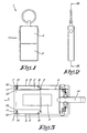
- FIGS 1 to 3 schematically represent a USB stick 1 according to the invention which mainly consists of a housing 2 with a memory and of a USB plug 3 protruding from the edge of the housing 2 and a cap 4 which can be provided with its open side over the USB plug 3.
- the USB stick 1 is further provided with means to connect the cap 4 and the housing 2 to one another, made as two parallel arms 5 in the given embodiment, which are fixed on the cap 4 and which protrude over a length in relation to the open side of the cap 4, such that the housing 2 is slidable and rotatable between said arms 5 in the longitudinal direction of the arms 5.
- each of the sides of the arms 5 that are directed towards one another is provided a groove 6 in the longitudinal direction of the arms 15, up to a short distance from the free end of the arm concerned, such that a stop 7 is formed at the free end defining the length of the groove 6.
- the housing 2 is provided with at least two protrusions 8, each on a side edge of the housing 2, which are each mounted slidably in one of the above-mentioned grooves 6, and which are partly situated in a recess 9 provided to that end in the side edge of the housing 2.
- protrusions 8 are preferably situated at two corners of the housing 2, on the edge from which the USB plug 3 protrudes.
- Said protrusions 8 can be made in the shape of balls.
- the protrusions 8 are made as represented in figure 10 .
- Such a protrusion 8 is formed of the free end of a pen 35 to which a plate 36 is fixed at the other end in such a manner that the plate 36 is at right angles to the axis of the pen 35.
- the groove 6 is provided in the arms 5 over the entire thickness of said arms 5.
- an additional undercut has been provided along the perimeter of the groove 6.
- the plate 36 rests in the undercut on the arms 5.
- Said plate 36 may for example be circular.
- the protrusion 8, formed of the free end of the pen 35, can be placed in the recess 9 provided to that end in the side edge of the housing 2.
- Said free end of the pen 35 may possibly be provided with a screw thread working in conjunction with a screw thread that has been provided in the recess 9.
- the arms 5 further comprise a cover plate 37 provided on the sides which are directed away from one another and which thus covers the groove 6 and the undercut on the outside.
- the protrusions 8 are preferably made of a material having a low coefficient of friction, such as Teflon for example.
- Additional protrusions 10 may possibly be provided which are preferably situated at the two other corners of the housing 2, the latter protrusions 10 being partly held in a recess 11 provided to that end in the side edges of the housing 2.
- both said protrusions 10 are maintained in the recess 11 by means of a ring 12 which covers the recess 11 and whose inner diameter is smaller than the diameter of the protrusion 10.
- This recess 11 is provided with a compressed spring 13 which pushes the protrusion 10 against the above-mentioned ring 12.
- Figure 10 shows an alternative embodiment of the protrusions 10. These protrusions 10 are hereby held in a case 38 which is fixed in the recess 11, for example by means of gluing or by means of a screw connection.
- said case 38 is provided with an inner collar.
- the protrusion 10 is formed of a pen provided with a stop. When the pen is put in the case 38, the far end of said pen can protrude from the case 38.
- the protrusion 10 can move in and out of the recess 11 by either or not exerting an axial force thereon.
- the free far end of the protrusion 10 is partly or entirely rounded.
- the method for opening the USB stick is very simple and as follows, and it is illustrated by means of figures 3 to 5 .
- USB plug 3 In its closed position, as represented in figures 1 to 3 , the USB plug 3 is protected by the cap 4 which is provided with its open side over the USB plug 3.
- the protrusions 10 will hereby be pushed over the stop 7 in the recesses 11, against the force of the springs 13, until the far end of the housing 2 has moved sufficiently, which makes it possible indeed to withdraw the housing 2 from the cap 4.
- the housing 2 is slidable over a length which depends on the length of the groove 6, which is such that the housing 2 is slidable over a length which is at least sufficient to draw the USB plug 3 out of the cap 4.
- the housing 2 can be rotated around the geometrical axis by the two protrusions 8 which are still situated in the groove 6 after the sliding movement.
- the housing 2 will be held with a certain resistance thanks to the springy action of the protrusions 10 which make contact with the arms 5 during the rotational movement of the housing 2 around the above-mentioned geometrical axis, after which, as it rotates further, the protrusions 10 are pushed in the grooves 6 of the arms 5 and thus lock the housing 2.
- the protrusions 10 are preferably situated at the far ends of the groove 6, such that the housing 2 is also locked in the longitudinal direction in the situation as represented, and it is therefore held in place when the USB plug 3 is put in a USB slot.
- the method for closing off the USB stick is very simple and as follows.
- the protrusions 10 By exerting a force perpendicular to the surface of the USB plug 3, and preferably as close as possible to the other side of the housing 2 than the one from which the USB plug 3 protrudes, the protrusions 10 will in their respective recesses 11 again be pushed by the edges of the grooves 6 in the arms 5, as a result of which the springs 13 are compressed.
- the housing 2 can be rotated until the housing 2 and the cap 4 are situated in one another's prolongation again, as represented in figure 4 , whereby the USB plug 3 is turned towards the open side of the cap 4.
- Small notches may possibly be provided in the arms 5, such that the protrusions 10 only have to be pushed partly in the recesses 11.
- the USB stick 1 is put in a stable, closed position, and the USB plug 3 is protected by the cap 4.
- the USB stick 1 may further be provided with means which make it possible to fix the USB stick 1 either or not temporarily to another object, such as for example a key ring or a chain, whereby these means may be detachable, for example by means of a quick coupling.
- said fixing means are made in the shape of a pen 14 which may be connected to an object of one's choice at its far end 15, and which may be provided in a detachable manner in a bore hole 17 of the USB stick 1 at its other far end.
- a groove 18 In the far end 16, along the perimeter of the pen 14, is provided a groove 18.
- the bore hole 17 is preferably situated in the cap 4 of the USB stick 1.
- the bore hole is provided with at least one radially directed seat 19 in which can be provided a ball 20.
- the USB stick 1 is further provided with means to eliminate the action of the spring 21 on the ball 20.
- said means are formed of an element 22 in the form of a slide situated in a guide according to the axial direction of the radial seat 19, which element 22 has been provided between the ball 20 and the spring 21 and a mechanism 15 which makes it possible to withdraw the element 22 in the direction of the bore hole 17.
- Said mechanism is preferably integrated in a body 23 which is provided with two control buttons 24 which can be pushed in a recess 25 of the body 23 provided to that end.
- Said control buttons 24 are each connected to a mechanism formed of two parallel gear racks 26,27 provided slidably in the body 23 in a direction which is parallel to the axial direction of the radial seat 19, and of a gear wheel 28 which is provided in a freely rotating manner between both gear racks 26,27 and which meshes in the teeth of both gear racks 26,27.
- One of the gear racks 27 is connected to the above-mentioned element 22 between the spring 21 and the ball 20, whereas the other gear rack 26 which is connected to the control button 24 has been provided in a guide 29.
- the body 22 may be further provided with recesses 30 in which locking screws or locking pins 31 may be provided, said recesses 30 ending in the recesses 25 of the control buttons 24.
- the method for removing the fixing pen 14 is very simple and as follows.
- Figure 6 shows the situation in which the pen 14 is locked in the housing 2 as the balls 20 are pushed in the groove 18 of the pen 14 by means of the springs 21.
- control buttons 24 are pushed in towards one another in the direction of the arrows B in figure 5 , as a result of which the mechanism of the two gear racks 26,27 and the gear wheel 28 is activated, whereby the gear rack 26 moves in its guide 29, such that the gear wheel 28 starts to rotate and the gear rack 27 which is connected to the element 22 is set in motion in a direction opposite to the direction of movement B.
- the length of the guide 29 is selected such that the gear rack 26 can shift over the required distance and prevents the control buttons 24 from being pushed in too deeply, such that the mechanism cannot be forced.
- the method for fixing the USB stick 1 to another object is very simple and as follows.
- the pen 14 will hereby push against the balls 20 in the radial seat 19 of the bore hole 17, such that said balls 20 are pushed in a radial direction, away from the pen 14, and compress the spring 21 which is connected to the ball 20 via the element 22.
- the groove 18 in the pen 14 will be situated at a given moment under the radial seat 19 with the balls 20, the balls 20 being pushed in the groove 18 by the springs 21, and the fixing pen 14 being thus firmly connected to the USB stick 1.
- the above-mentioned body 23 is a block-shaped part which is provided in the cavity of the cap 4 of the USB stick 1, said body 23 being held in the cap 4 as the control buttons 24 protrude through passages 32 in the cap 4, the locking screws 31 preventing the buttons 24 from being pushed in too deeply, as a result of which the body 23 would be possibly released.
- This type of mounting moreover makes it possible to apply the above-mentioned mechanism in a very simple manner in the cap 4 during the assembly of the USB stick 1, in the following manner.
- the body 23 is pushed in the cap 4 via the open side by pressing the control buttons 24 against the force of the springs 21.
- control buttons 24 are thereby pressed entirely in their recesses 25 and they are held in this position by the locking screws 31, such that the control buttons do not form a protruding part on the body 23 and cannot be damaged while the body 23 is being inserted.
- control buttons 24 are situated on the outside of the USB stick, they will be fastened again by means of the locking screws 31.
- the body 23 will be locked in the cap 4 when mounted since the control button 24, under the influence of the above-mentioned spring 21, snaps into a passage 32 of the cap 4, and the movement of the control buttons 24 will be restricted by the locking screws 31, such that the control buttons 24 cannot be pushed in too deeply.
- the body 23 can be removed from the cap 4 in a very simple manner by unscrewing the locking screws 31 and by pressing the control buttons 24, by fastening them again such that they become locked in their recesses 25, after which the body 23 can be removed from the cap 4.
- the balls 20 have been replaced by pens 33 which are preferably wedge-shaped and which can work in conjunction with a wedge-shaped groove in the pen 14, the slanting part 34 of the pens 33 having a slope towards the bore hole 17 in the direction of the interior of the cap 4.
- the far end 16 of the pen 14 can also be provided with a conical shape having the same slope as the pens 33, such that when the pen 14 is inserted, it can co-operate with the pens 33 and push them against the direction of the spring 21.
- the pens 33 may also have other shapes such as for example cylindrical elements.
- FIGS 10 and 11 show another variant of an embodiment of the means which make it possible to fix the USB stick 1 either or not temporarily to another object.
- These means mainly comprise two slide-shaped elements 40,41 which can co-operate to partly seal the hole of the bore hole 17 in the USB stick 1 over a limited distance of said bore hole 17.
- Figure 11 shows that these slide-shaped elements 40,41 have a predominantly L-shaped section.
- the slide-shaped elements 40,41 are positioned in relation to one another in such a way that their long legs 42 partly overlap.
- the short legs 43 point in the direction of the other slide-shaped element 40,41, at least seen in relation to the longitudinal direction of the long legs 42.
- each of the sides of the long legs 42 that are directed towards each other are provided two partly overlapping semi-circular passages.
- One passage has a larger diameter than the other one, such that in a specific position of the two slide-shaped elements 40,41, when the springs 44 are released somewhat more, the two smaller semi-circular passages are situated opposite one another and thus together form a small circular passage.
- the common passage will become larger, until a position is reached in which the two larger semi-circular passages are situated opposite one another and thus together form a large circular passage.
- edges 45 of the opening of the slide-shaped elements 40,41 are bevelled towards the inside.
- This mechanism is preferably integrated in a body 23 which can be provided in the cap 4, such that the control buttons 24 can be operated from outside, on the side of the USB stick 1.
- the method for removing the pen 14 is very simple and as follows.
- the pen 14 In the initial position, the pen 14 is locked in the housing 2. As the control buttons 24 are not pressed, the slide-shaped elements 40,41 are positioned to each other in such a way that they partly cover the hole of the bore hole 17. The part of the pen 14 over which the groove 18 is provided is enclosed by said sealing.
- the hole formed by the slide-shaped elements 40,41 is not so large that the entire diameter of the pen 14 can move through it. If the pen 14 is being drawn at, the edge of the pen 14 formed by the groove 18 will remain hooked on the slide-shaped elements 40,41.
- the pen 14 shall hereby push against the bevelled edge 45 of the slide-shaped elements 40,41.
- the slide-shaped elements 40,41 will move away from each other, against the pressure of the springs 44, such that the free opening between these elements becomes larger.
- the fixing pen 14 is solidly connected to the USB stick 1 in this way.
- the above-described mechanism can be easily applied in the cap 4 during the assembly of the USB stick 1 in the following way.
- the body 23 On the side which is directed towards the bore hole 17 during the assembly, the body 23 is provided with a U-shaped recess in which the slide-shaped elements 40,41 can be provided with the springs 44.
- This recess has such a shape and dimensions that the studs 46 but not the bodies of the slide-shaped elements 40,41 can protrude laterally from the U-shaped recess of the body 23.
- the control buttons 24 are not yet mounted on the studs 46 then.
- the studs 46 In order to push the body 23 via the open side in the cap 4, the studs 46 must be pushed further in the body 23, such that the body 23 can be provided in the cap 4.
- the springs 44 will be released and they will push the studs 46 through the passages 32 to the outside of the USB stick 1.
- control buttons 24 can then be mounted on the studs 46, for example by means of gluing or by means of a threaded connection.
- the USB stick can be attached to an object without thereby having to use the control buttons 24.
- USB stick 1 is secured against any accidental detachments, since the pen 14 can only be detached when both control buttons 24 are simultaneously pressed.
- the housing 2 of the USB plug with an opening in the shape of a viewing window, whereby the USB stick 1 may further be provided with a led situated behind the viewing window, and which may indicate whether the USB stick 1 is either or not in use.
- control buttons 24 Although the embodiments shown in the figures have two control buttons 24, it is not excluded according to the invention to provide only one control button 24 and to further simplify the fastening mechanism.
- USB stick according to the invention can be made in all sorts of shapes and dimensions while still remaining within the scope of the invention.
Landscapes
- Engineering & Computer Science (AREA)
- Microelectronics & Electronic Packaging (AREA)
- Connector Housings Or Holding Contact Members (AREA)
- Pens And Brushes (AREA)
- Saccharide Compounds (AREA)
- Acyclic And Carbocyclic Compounds In Medicinal Compositions (AREA)
Claims (13)
- Clé USB (1) du type qui est constitué principalement par un boîtier (2) comportant une mémoire et un connecteur USB (3) faisant saillie par rapport à un bord du boîtier (2) et par un capuchon (4) qui peut venir se placer par-dessus le connecteur USB (3), avec un côté ouvert de façon à pouvoir protéger cette dernière, la clé USB (1) étant munie de moyens qui relient le boîtier (2) et le capuchon (4), aussi bien dans la position ouverte que dans la position fermée, et le moyen susmentionné étant constitué par deux bras parallèles (5) qui sont fixés au capuchon (4) et qui, par rapport au côté ouvert susmentionné, font saillie par rapport au capuchon (4) sur une certaine longueur, le boîtier (2) avec le connecteur USB (3) étant à même de coulisser entre lesdits bras (5) dans la direction longitudinale desdits bras (5) et étant également rotatif, et le boîtier (2) étant à même de coulisser au moyen d'au moins deux saillies (8), une sur chaque bord latéral du boîtier (2), lesdites saillies (8) étant montées en coulissement dans une rainure (6) dans les côtés des bras susmentionnés (5) qui sont orientés l'un vers l'autre, caractérisée en ce que les saillies (8) sont prévues aux coins du boîtier (2) sur le bord desquels fait saillie le connecteur USB (3), et en ce que les saillies (10) sont également prévues aux autres coins du boîtier (2) qui sont maintenus dans un évidement (11) dans les bords latéraux du boîtier (2) et qui peuvent être comprimés à l'encontre de la force exercée par un ressort (13) qui est situé en dessous de la saillie (10) dans l'évidement (11) concerné.
- Clé USB (1) selon la revendication 1, caractérisée en ce que le boîtier (2) est à même d'effectuer des rotations sur 180°.
- Clé USB (1) selon la revendication 1 ou 2, caractérisée en ce que le boîtier (2) est à même de coulisser sur une longueur qui est suffisante pour tirer le connecteur USB (3) hors du capuchon (4).
- Clé USB (1) selon l'une quelconque des revendications précédentes, caractérisée en ce que les saillies susmentionnées (8) sont des billes qui sont maintenues en partie dans un évidement (9) dans les bords latéraux susmentionnés du boîtier (2).
- Clé USB (1) selon l'une quelconque des revendications précédentes, caractérisée en ce que les rainures (6) sont munies d'un arrêt (7) aux extrémités éloignées libres des bras (5) pour le mouvement de coulissement des saillies susmentionnées (8).
- Clé USB (1) selon l'une quelconque des revendications précédentes en combinaison avec la revendication 2, caractérisée en ce que le boîtier (2) de la clé USB (1) est verrouillé à l'état prêt à l'emploi dans lequel elle a effectué une rotation, en direction longitudinale, par le fait que les saillies (10) sont situées aux coins de l'autre bord par rapport à celui à partir duquel fait saillie le connecteur USB (3).
- Clé USB (1) selon l'une quelconque des revendications précédentes, caractérisée en ce que la clé USB (1) est munie de moyens pour une fixation au moins temporaire de la clé USB (1) à un autre objet, ces moyens étant amovibles.
- Clé USB (1) selon la revendication 7, caractérisée en ce que les moyens de fixation susmentionnés comprennent un stylo (14) qui vient se fixer dans un alésage (17) dans la clé USB (1), l'alésage (17) étant muni d'un siège (19) au moins orienté en direction radiale pour une bille (20) ou pour un stylo (33), qui est à même de coopérer avec une rainure (18) au moyen d'un ressort (21) le long du périmètre de l'extrémité éloignée du stylo (14) de façon à verrouiller le dernier cité.
- Clé USB (1) selon la revendication 8, caractérisée en ce que des moyens sont prévus pour supprimer l'action du ressort (21) s'exerçant sur la bille (20) ou sur le stylo (33).
- Clé USB (1) selon la revendication 9, caractérisée en ce que les moyens susmentionnés sont réalisés à partir d'un élément (22) prévu entre la bille (20) ou le stylo (33) et le ressort (21) et d'un mécanisme qui permet de tirer l'élément (22) hors de l'alésage (17).
- Clé USB (1) selon la revendication 10, caractérisée en ce que ledit mécanisme est constitué par un bouton de commande (24) qui est relié à une crémaillère (26) qui travaille conjointement avec une roue dentée (28) qui travaille à son tour conjointement avec une crémaillère (27) qui est reliée à l'élément (22) susmentionné entre le ressort (21) et la bille (20) ou le stylo (33), tant et si bien que, lorsque le bouton de commande (24) est enfoncé, l'élément (22) est retiré de l'alésage (17).
- Clé USB (1) selon la revendication 7, caractérisée en ce que les moyens de fixation susmentionnés comprennent un stylo (14) qui vient s'insérer dans un alésage (17) dans la clé USB (1), des éléments (40, 41) étant prévus dans le capuchon (4) de façon à pouvoir coulisser dans chaque prolongement réciproque à au moins deux positions, plus précisément une première position de repos dans laquelle les éléments (40, 41) sont poussés à l'écart l'un de l'autre sous l'influence d'au moins un ressort (44) et, première position dans laquelle les éléments (40, 41) définissent ensemble une ouverture possédant un premier diamètre, et une deuxième position dans laquelle les éléments (40, 41) sont poussés l'un vers l'autre en enfonçant au moins un bouton de commande (24) faisant saillie en direction latérale, et deuxième position dans laquelle les éléments (40, 41) définissent ensemble une ouverture possédant un deuxième diamètre qui est supérieur au premier diamètre, le deuxième diamètre étant plus grand que le diamètre du stylo (14) et le premier diamètre étant plus petit que le diamètre du stylo (14), mais plus grand que le diamètre d'une rainure circonférentielle (18) prévue sur la tête du stylo (14).
- Clé USB (1) selon la revendication 12, caractérisée en ce qu'on obtient le premier et le deuxième diamètre lorsqu'on prévoit les éléments (40, 41) dans une position dans laquelle ils se chevauchent en partie dans leur direction longitudinale, et en ce cas dans chacun des éléments (40, 41), dans les parties chevauchantes, on prévoit deux passages semi-circulaires, les passages semi-circulaires possédant le plus petit diamètre étant disposés plus loin du bouton de commande (24) avec leurs centres que les passages semi-circulaires possédant le plus grand diamètre.
Priority Applications (1)
| Application Number | Priority Date | Filing Date | Title |
|---|---|---|---|
| PL08858560T PL2223582T3 (pl) | 2007-12-10 | 2008-12-08 | Pamięć USB |
Applications Claiming Priority (2)
| Application Number | Priority Date | Filing Date | Title |
|---|---|---|---|
| BE2007/0587A BE1017870A3 (nl) | 2007-12-10 | 2007-12-10 | Usb-stick. |
| PCT/BE2008/000100 WO2009073936A2 (fr) | 2007-12-10 | 2008-12-08 | Clé usb |
Publications (3)
| Publication Number | Publication Date |
|---|---|
| EP2223582A2 EP2223582A2 (fr) | 2010-09-01 |
| EP2223582B1 true EP2223582B1 (fr) | 2011-11-09 |
| EP2223582B8 EP2223582B8 (fr) | 2012-02-22 |
Family
ID=39768971
Family Applications (1)
| Application Number | Title | Priority Date | Filing Date |
|---|---|---|---|
| EP08858560A Not-in-force EP2223582B8 (fr) | 2007-12-10 | 2008-12-08 | Clé usb |
Country Status (7)
| Country | Link |
|---|---|
| US (1) | US20100255697A1 (fr) |
| EP (1) | EP2223582B8 (fr) |
| AT (1) | ATE533342T1 (fr) |
| BE (1) | BE1017870A3 (fr) |
| ES (1) | ES2377271T3 (fr) |
| PL (1) | PL2223582T3 (fr) |
| WO (1) | WO2009073936A2 (fr) |
Cited By (6)
| Publication number | Priority date | Publication date | Assignee | Title |
|---|---|---|---|---|
| CN106992380A (zh) * | 2017-02-21 | 2017-07-28 | 佛山澹雅自动化技术开发有限公司 | 一种可隔断的供电装置 |
| CN107332046A (zh) * | 2017-02-21 | 2017-11-07 | 佛山澹雅自动化技术开发有限公司 | 一种安全供电装置 |
| CN107332015A (zh) * | 2017-02-21 | 2017-11-07 | 佛山澹雅自动化技术开发有限公司 | 一种可隔断的插头插座设备 |
| CN107332045A (zh) * | 2017-02-21 | 2017-11-07 | 佛山澹雅自动化技术开发有限公司 | 一种可隔断的安全供电装置 |
| CN107332016A (zh) * | 2017-02-21 | 2017-11-07 | 佛山澹雅自动化技术开发有限公司 | 一种可隔断的插头插座装置 |
| CN111654987A (zh) * | 2020-06-04 | 2020-09-11 | 维沃移动通信(杭州)有限公司 | 电子设备 |
Families Citing this family (21)
| Publication number | Priority date | Publication date | Assignee | Title |
|---|---|---|---|---|
| US20120100822A1 (en) * | 2010-10-25 | 2012-04-26 | Bandrich, Inc. | Wireless network receiver for selectively receiving or exposing an electrical connector |
| TW201244598A (en) * | 2011-04-22 | 2012-11-01 | Walton Advanced Eng Inc | Thin carrier device |
| IL228846A (en) * | 2013-10-13 | 2015-11-30 | Lior Shabtay | A portable electric installation is integrated into the key |
| USD759031S1 (en) * | 2014-12-15 | 2016-06-14 | Bloomberg Finance L.P. | Electronic fob and fob carrier |
| CN104757748B (zh) * | 2015-04-29 | 2017-12-29 | 冷朝阳 | 一种改进的钥匙扣环 |
| CN104795680A (zh) * | 2015-05-08 | 2015-07-22 | 楼碧云 | 一种供电设备及其使用方法 |
| CN104795683A (zh) * | 2015-05-08 | 2015-07-22 | 王惠苗 | 一种使用限位传感器的供电设备及其使用方法 |
| CN104795679A (zh) * | 2015-05-08 | 2015-07-22 | 楼碧云 | 一种防松脱的供电设备及其使用方法 |
| CN104810665A (zh) * | 2015-05-08 | 2015-07-29 | 楼碧云 | 一种通过螺纹配合连接的供电设备及其使用方法 |
| CN104810668A (zh) * | 2015-05-08 | 2015-07-29 | 毛玲波 | 一种带导向槽的供电设备及其使用方法 |
| CN104795677A (zh) * | 2015-05-08 | 2015-07-22 | 尚庆光 | 一种使用夹紧装置的供电设备及其使用方法 |
| CN104795678A (zh) * | 2015-05-08 | 2015-07-22 | 楼碧云 | 一种散热快的供电设备及其使用方法 |
| CN104836055A (zh) * | 2015-05-08 | 2015-08-12 | 庆元华太商贸有限公司 | 一种可实现自锁的供电设备及其使用方法 |
| CN104810666A (zh) * | 2015-05-08 | 2015-07-29 | 毛玲波 | 一种带锁紧功能的供电设备及其使用方法 |
| CN105105419B (zh) * | 2015-09-08 | 2017-09-01 | 冷朝阳 | 一种自动闭合的钥匙扣环 |
| CN107440500A (zh) * | 2017-03-31 | 2017-12-08 | 广州尚儒自控系统工程有限公司 | 一种新型烧水壶装置 |
| CN107440499A (zh) * | 2017-03-31 | 2017-12-08 | 广州尚儒自控系统工程有限公司 | 一种耐用烧水壶装置 |
| CN107440501A (zh) * | 2017-03-31 | 2017-12-08 | 广州尚儒自控系统工程有限公司 | 一种新型烧水壶结构 |
| CN107440497A (zh) * | 2017-03-31 | 2017-12-08 | 广州尚儒自控系统工程有限公司 | 一种烧水壶装置 |
| CN108808354B (zh) * | 2018-06-04 | 2023-11-24 | 安徽艾伊德动力科技有限公司 | 一种电动汽车用防水型高压连接器 |
| CN109982530B (zh) * | 2019-03-19 | 2022-01-28 | 宁夏尚锐科技有限公司 | 一种便于安装的通信设备 |
Family Cites Families (11)
| Publication number | Priority date | Publication date | Assignee | Title |
|---|---|---|---|---|
| DE29818884U1 (de) * | 1998-10-23 | 1999-02-11 | Inform Plastik GmbH, 32657 Lemgo | Schlüsselanhänger |
| TW555047U (en) * | 2002-10-28 | 2003-09-21 | Walton Advanced Eng Inc | Thin type USB personal disc |
| KR100424781B1 (ko) * | 2003-09-01 | 2004-03-31 | 에스티에스반도체통신 주식회사 | 양방향단자 usb 플러그를 구비한 usb 저장장치 |
| TW200612221A (en) * | 2004-10-08 | 2006-04-16 | Compal Electronics Inc | Portable storage device with multiple interfaces |
| TWM271191U (en) * | 2004-12-31 | 2005-07-21 | Inventec Multimedia & Telecom | Electronic apparatus with cap structure |
| US20070084929A1 (en) * | 2005-10-17 | 2007-04-19 | Hitoshi Watanabe | Barcode reader with a music player |
| US7500858B2 (en) * | 2006-07-27 | 2009-03-10 | Micron Technology, Inc. | Portable electronic device with built-in terminal cover structure |
| TW200812166A (en) * | 2006-08-25 | 2008-03-01 | sheng-xing Liao | Transfer plug |
| TWI323056B (en) * | 2006-09-27 | 2010-04-01 | Asustek Comp Inc | Removable storage device |
| US7850468B2 (en) * | 2007-06-28 | 2010-12-14 | Super Talent Electronics, Inc. | Lipstick-type USB device |
| US7789680B2 (en) * | 2007-07-05 | 2010-09-07 | Super Talent Electronics, Inc. | USB device with connected cap |
-
2007
- 2007-12-10 BE BE2007/0587A patent/BE1017870A3/nl not_active IP Right Cessation
-
2008
- 2008-12-08 EP EP08858560A patent/EP2223582B8/fr not_active Not-in-force
- 2008-12-08 WO PCT/BE2008/000100 patent/WO2009073936A2/fr not_active Ceased
- 2008-12-08 ES ES08858560T patent/ES2377271T3/es active Active
- 2008-12-08 PL PL08858560T patent/PL2223582T3/pl unknown
- 2008-12-08 US US12/746,799 patent/US20100255697A1/en not_active Abandoned
- 2008-12-08 AT AT08858560T patent/ATE533342T1/de active
Cited By (6)
| Publication number | Priority date | Publication date | Assignee | Title |
|---|---|---|---|---|
| CN106992380A (zh) * | 2017-02-21 | 2017-07-28 | 佛山澹雅自动化技术开发有限公司 | 一种可隔断的供电装置 |
| CN107332046A (zh) * | 2017-02-21 | 2017-11-07 | 佛山澹雅自动化技术开发有限公司 | 一种安全供电装置 |
| CN107332015A (zh) * | 2017-02-21 | 2017-11-07 | 佛山澹雅自动化技术开发有限公司 | 一种可隔断的插头插座设备 |
| CN107332045A (zh) * | 2017-02-21 | 2017-11-07 | 佛山澹雅自动化技术开发有限公司 | 一种可隔断的安全供电装置 |
| CN107332016A (zh) * | 2017-02-21 | 2017-11-07 | 佛山澹雅自动化技术开发有限公司 | 一种可隔断的插头插座装置 |
| CN111654987A (zh) * | 2020-06-04 | 2020-09-11 | 维沃移动通信(杭州)有限公司 | 电子设备 |
Also Published As
| Publication number | Publication date |
|---|---|
| PL2223582T3 (pl) | 2012-05-31 |
| EP2223582A2 (fr) | 2010-09-01 |
| ATE533342T1 (de) | 2011-11-15 |
| WO2009073936A3 (fr) | 2010-04-01 |
| WO2009073936A2 (fr) | 2009-06-18 |
| EP2223582B8 (fr) | 2012-02-22 |
| BE1017870A3 (nl) | 2009-09-01 |
| US20100255697A1 (en) | 2010-10-07 |
| ES2377271T3 (es) | 2012-03-26 |
Similar Documents
| Publication | Publication Date | Title |
|---|---|---|
| EP2223582B1 (fr) | Clé usb | |
| US7572049B2 (en) | Timepiece | |
| CN104062878B (zh) | 开关装置及具备开关装置的钟表 | |
| JP7465932B2 (ja) | 計時器のための胴に裏蓋を締結するデバイス | |
| CN110114543B (zh) | 带钥匙保持的压缩闩锁 | |
| JP2504713B2 (ja) | 引出し回転型扉用ロックハンドル装置 | |
| CN110023040A (zh) | 操作棒的连结结构 | |
| CN107044475A (zh) | 车轮螺母组件 | |
| JP7358763B2 (ja) | バンドおよび時計 | |
| US6644149B2 (en) | Extraction tool for tanged helically coiled inserts with improved removability | |
| US4800785A (en) | Dual-drive ratchet wrench | |
| JP4403787B2 (ja) | 簡易締結装置 | |
| KR101876258B1 (ko) | 회전 핸들용 캡 | |
| US8479620B2 (en) | Torque-setting device | |
| AU2005200672B8 (en) | Screw driver including a holding device | |
| CN108060704B (zh) | 按钮滑座 | |
| US20200238749A1 (en) | Multifunctional writing instrument | |
| US20080087058A1 (en) | Unfastening-proof structure for nut sleeves of quick release locks | |
| US10876320B2 (en) | Locking device with lockable spindle follower linkage | |
| WO2003070487A1 (fr) | Instrument d'ecriture retractable | |
| WO2008105675A1 (fr) | Collier de cordon pour connecteur ou appareil électrique | |
| TWI659806B (zh) | 扭力套筒結構 | |
| US7121753B2 (en) | Pen | |
| WO2021024355A1 (fr) | Cadenas | |
| CN223413527U (zh) | 转接结构 |
Legal Events
| Date | Code | Title | Description |
|---|---|---|---|
| PUAI | Public reference made under article 153(3) epc to a published international application that has entered the european phase |
Free format text: ORIGINAL CODE: 0009012 |
|
| 17P | Request for examination filed |
Effective date: 20100702 |
|
| AK | Designated contracting states |
Kind code of ref document: A2 Designated state(s): AT BE BG CH CY CZ DE DK EE ES FI FR GB GR HR HU IE IS IT LI LT LU LV MC MT NL NO PL PT RO SE SI SK TR |
|
| AX | Request for extension of the european patent |
Extension state: AL BA MK RS |
|
| 17Q | First examination report despatched |
Effective date: 20110121 |
|
| DAX | Request for extension of the european patent (deleted) | ||
| GRAP | Despatch of communication of intention to grant a patent |
Free format text: ORIGINAL CODE: EPIDOSNIGR1 |
|
| GRAC | Information related to communication of intention to grant a patent modified |
Free format text: ORIGINAL CODE: EPIDOSCIGR1 |
|
| GRAC | Information related to communication of intention to grant a patent modified |
Free format text: ORIGINAL CODE: EPIDOSCIGR1 |
|
| GRAS | Grant fee paid |
Free format text: ORIGINAL CODE: EPIDOSNIGR3 |
|
| GRAA | (expected) grant |
Free format text: ORIGINAL CODE: 0009210 |
|
| AK | Designated contracting states |
Kind code of ref document: B1 Designated state(s): AT BE BG CH CY CZ DE DK EE ES FI FR GB GR HR HU IE IS IT LI LT LU LV MC MT NL NO PL PT RO SE SI SK TR |
|
| REG | Reference to a national code |
Ref country code: GB Ref legal event code: FG4D |
|
| REG | Reference to a national code |
Ref country code: CH Ref legal event code: EP |
|
| RAP2 | Party data changed (patent owner data changed or rights of a patent transferred) |
Owner name: NINE AND SIX, BESLOTEN VENNOOTSCHAP MET BEPERKTE A |
|
| REG | Reference to a national code |
Ref country code: IE Ref legal event code: FG4D |
|
| REG | Reference to a national code |
Ref country code: CH Ref legal event code: NV Representative=s name: N&G PATENT SERVICES SA |
|
| REG | Reference to a national code |
Ref country code: NL Ref legal event code: T3 |
|
| PGFP | Annual fee paid to national office [announced via postgrant information from national office to epo] |
Ref country code: IE Payment date: 20111214 Year of fee payment: 4 |
|
| REG | Reference to a national code |
Ref country code: DE Ref legal event code: R096 Ref document number: 602008011328 Country of ref document: DE Effective date: 20120216 |
|
| REG | Reference to a national code |
Ref country code: ES Ref legal event code: FG2A Ref document number: 2377271 Country of ref document: ES Kind code of ref document: T3 Effective date: 20120326 |
|
| LTIE | Lt: invalidation of european patent or patent extension |
Effective date: 20111109 |
|
| PG25 | Lapsed in a contracting state [announced via postgrant information from national office to epo] |
Ref country code: LT Free format text: LAPSE BECAUSE OF FAILURE TO SUBMIT A TRANSLATION OF THE DESCRIPTION OR TO PAY THE FEE WITHIN THE PRESCRIBED TIME-LIMIT Effective date: 20111109 Ref country code: NO Free format text: LAPSE BECAUSE OF FAILURE TO SUBMIT A TRANSLATION OF THE DESCRIPTION OR TO PAY THE FEE WITHIN THE PRESCRIBED TIME-LIMIT Effective date: 20120209 Ref country code: IS Free format text: LAPSE BECAUSE OF FAILURE TO SUBMIT A TRANSLATION OF THE DESCRIPTION OR TO PAY THE FEE WITHIN THE PRESCRIBED TIME-LIMIT Effective date: 20120309 |
|
| PG25 | Lapsed in a contracting state [announced via postgrant information from national office to epo] |
Ref country code: HR Free format text: LAPSE BECAUSE OF FAILURE TO SUBMIT A TRANSLATION OF THE DESCRIPTION OR TO PAY THE FEE WITHIN THE PRESCRIBED TIME-LIMIT Effective date: 20111109 Ref country code: GR Free format text: LAPSE BECAUSE OF FAILURE TO SUBMIT A TRANSLATION OF THE DESCRIPTION OR TO PAY THE FEE WITHIN THE PRESCRIBED TIME-LIMIT Effective date: 20120210 Ref country code: PT Free format text: LAPSE BECAUSE OF FAILURE TO SUBMIT A TRANSLATION OF THE DESCRIPTION OR TO PAY THE FEE WITHIN THE PRESCRIBED TIME-LIMIT Effective date: 20120309 Ref country code: LV Free format text: LAPSE BECAUSE OF FAILURE TO SUBMIT A TRANSLATION OF THE DESCRIPTION OR TO PAY THE FEE WITHIN THE PRESCRIBED TIME-LIMIT Effective date: 20111109 Ref country code: SE Free format text: LAPSE BECAUSE OF FAILURE TO SUBMIT A TRANSLATION OF THE DESCRIPTION OR TO PAY THE FEE WITHIN THE PRESCRIBED TIME-LIMIT Effective date: 20111109 Ref country code: SI Free format text: LAPSE BECAUSE OF FAILURE TO SUBMIT A TRANSLATION OF THE DESCRIPTION OR TO PAY THE FEE WITHIN THE PRESCRIBED TIME-LIMIT Effective date: 20111109 |
|
| REG | Reference to a national code |
Ref country code: PL Ref legal event code: T3 |
|
| PG25 | Lapsed in a contracting state [announced via postgrant information from national office to epo] |
Ref country code: CY Free format text: LAPSE BECAUSE OF FAILURE TO SUBMIT A TRANSLATION OF THE DESCRIPTION OR TO PAY THE FEE WITHIN THE PRESCRIBED TIME-LIMIT Effective date: 20111109 |
|
| PG25 | Lapsed in a contracting state [announced via postgrant information from national office to epo] |
Ref country code: DK Free format text: LAPSE BECAUSE OF FAILURE TO SUBMIT A TRANSLATION OF THE DESCRIPTION OR TO PAY THE FEE WITHIN THE PRESCRIBED TIME-LIMIT Effective date: 20111109 Ref country code: EE Free format text: LAPSE BECAUSE OF FAILURE TO SUBMIT A TRANSLATION OF THE DESCRIPTION OR TO PAY THE FEE WITHIN THE PRESCRIBED TIME-LIMIT Effective date: 20111109 Ref country code: SK Free format text: LAPSE BECAUSE OF FAILURE TO SUBMIT A TRANSLATION OF THE DESCRIPTION OR TO PAY THE FEE WITHIN THE PRESCRIBED TIME-LIMIT Effective date: 20111109 Ref country code: CZ Free format text: LAPSE BECAUSE OF FAILURE TO SUBMIT A TRANSLATION OF THE DESCRIPTION OR TO PAY THE FEE WITHIN THE PRESCRIBED TIME-LIMIT Effective date: 20111109 Ref country code: BG Free format text: LAPSE BECAUSE OF FAILURE TO SUBMIT A TRANSLATION OF THE DESCRIPTION OR TO PAY THE FEE WITHIN THE PRESCRIBED TIME-LIMIT Effective date: 20120209 |
|
| PG25 | Lapsed in a contracting state [announced via postgrant information from national office to epo] |
Ref country code: RO Free format text: LAPSE BECAUSE OF FAILURE TO SUBMIT A TRANSLATION OF THE DESCRIPTION OR TO PAY THE FEE WITHIN THE PRESCRIBED TIME-LIMIT Effective date: 20111109 |
|
| PLBE | No opposition filed within time limit |
Free format text: ORIGINAL CODE: 0009261 |
|
| STAA | Information on the status of an ep patent application or granted ep patent |
Free format text: STATUS: NO OPPOSITION FILED WITHIN TIME LIMIT |
|
| REG | Reference to a national code |
Ref country code: AT Ref legal event code: MK05 Ref document number: 533342 Country of ref document: AT Kind code of ref document: T Effective date: 20111109 |
|
| 26N | No opposition filed |
Effective date: 20120810 |
|
| REG | Reference to a national code |
Ref country code: DE Ref legal event code: R097 Ref document number: 602008011328 Country of ref document: DE Effective date: 20120810 |
|
| PG25 | Lapsed in a contracting state [announced via postgrant information from national office to epo] |
Ref country code: AT Free format text: LAPSE BECAUSE OF FAILURE TO SUBMIT A TRANSLATION OF THE DESCRIPTION OR TO PAY THE FEE WITHIN THE PRESCRIBED TIME-LIMIT Effective date: 20111109 |
|
| PG25 | Lapsed in a contracting state [announced via postgrant information from national office to epo] |
Ref country code: MT Free format text: LAPSE BECAUSE OF FAILURE TO SUBMIT A TRANSLATION OF THE DESCRIPTION OR TO PAY THE FEE WITHIN THE PRESCRIBED TIME-LIMIT Effective date: 20111109 |
|
| PGFP | Annual fee paid to national office [announced via postgrant information from national office to epo] |
Ref country code: GB Payment date: 20121221 Year of fee payment: 5 |
|
| PGFP | Annual fee paid to national office [announced via postgrant information from national office to epo] |
Ref country code: ES Payment date: 20121228 Year of fee payment: 5 |
|
| PGFP | Annual fee paid to national office [announced via postgrant information from national office to epo] |
Ref country code: NL Payment date: 20121228 Year of fee payment: 5 |
|
| PG25 | Lapsed in a contracting state [announced via postgrant information from national office to epo] |
Ref country code: FI Free format text: LAPSE BECAUSE OF FAILURE TO SUBMIT A TRANSLATION OF THE DESCRIPTION OR TO PAY THE FEE WITHIN THE PRESCRIBED TIME-LIMIT Effective date: 20111109 |
|
| REG | Reference to a national code |
Ref country code: IE Ref legal event code: MM4A |
|
| PG25 | Lapsed in a contracting state [announced via postgrant information from national office to epo] |
Ref country code: TR Free format text: LAPSE BECAUSE OF FAILURE TO SUBMIT A TRANSLATION OF THE DESCRIPTION OR TO PAY THE FEE WITHIN THE PRESCRIBED TIME-LIMIT Effective date: 20111109 |
|
| PG25 | Lapsed in a contracting state [announced via postgrant information from national office to epo] |
Ref country code: IE Free format text: LAPSE BECAUSE OF NON-PAYMENT OF DUE FEES Effective date: 20121208 Ref country code: HU Free format text: LAPSE BECAUSE OF FAILURE TO SUBMIT A TRANSLATION OF THE DESCRIPTION OR TO PAY THE FEE WITHIN THE PRESCRIBED TIME-LIMIT Effective date: 20111109 |
|
| PGFP | Annual fee paid to national office [announced via postgrant information from national office to epo] |
Ref country code: MC Payment date: 20131230 Year of fee payment: 6 |
|
| PG25 | Lapsed in a contracting state [announced via postgrant information from national office to epo] |
Ref country code: PL Free format text: LAPSE BECAUSE OF NON-PAYMENT OF DUE FEES Effective date: 20121208 |
|
| REG | Reference to a national code |
Ref country code: NL Ref legal event code: V1 Effective date: 20140701 |
|
| GBPC | Gb: european patent ceased through non-payment of renewal fee |
Effective date: 20131208 |
|
| PG25 | Lapsed in a contracting state [announced via postgrant information from national office to epo] |
Ref country code: NL Free format text: LAPSE BECAUSE OF NON-PAYMENT OF DUE FEES Effective date: 20140701 |
|
| PG25 | Lapsed in a contracting state [announced via postgrant information from national office to epo] |
Ref country code: GB Free format text: LAPSE BECAUSE OF NON-PAYMENT OF DUE FEES Effective date: 20131208 |
|
| REG | Reference to a national code |
Ref country code: ES Ref legal event code: FD2A Effective date: 20150327 |
|
| PG25 | Lapsed in a contracting state [announced via postgrant information from national office to epo] |
Ref country code: ES Free format text: LAPSE BECAUSE OF NON-PAYMENT OF DUE FEES Effective date: 20131209 |
|
| REG | Reference to a national code |
Ref country code: FR Ref legal event code: PLFP Year of fee payment: 8 |
|
| PGFP | Annual fee paid to national office [announced via postgrant information from national office to epo] |
Ref country code: DE Payment date: 20151221 Year of fee payment: 8 Ref country code: IT Payment date: 20151231 Year of fee payment: 8 |
|
| PG25 | Lapsed in a contracting state [announced via postgrant information from national office to epo] |
Ref country code: MC Free format text: LAPSE BECAUSE OF NON-PAYMENT OF DUE FEES Effective date: 20141231 |
|
| REG | Reference to a national code |
Ref country code: FR Ref legal event code: PLFP Year of fee payment: 9 |
|
| PGFP | Annual fee paid to national office [announced via postgrant information from national office to epo] |
Ref country code: LU Payment date: 20161123 Year of fee payment: 9 |
|
| REG | Reference to a national code |
Ref country code: DE Ref legal event code: R119 Ref document number: 602008011328 Country of ref document: DE |
|
| PG25 | Lapsed in a contracting state [announced via postgrant information from national office to epo] |
Ref country code: IT Free format text: LAPSE BECAUSE OF NON-PAYMENT OF DUE FEES Effective date: 20161208 |
|
| PG25 | Lapsed in a contracting state [announced via postgrant information from national office to epo] |
Ref country code: DE Free format text: LAPSE BECAUSE OF NON-PAYMENT OF DUE FEES Effective date: 20170701 |
|
| REG | Reference to a national code |
Ref country code: FR Ref legal event code: PLFP Year of fee payment: 10 |
|
| PGFP | Annual fee paid to national office [announced via postgrant information from national office to epo] |
Ref country code: FR Payment date: 20171229 Year of fee payment: 10 |
|
| PGFP | Annual fee paid to national office [announced via postgrant information from national office to epo] |
Ref country code: CH Payment date: 20180123 Year of fee payment: 10 |
|
| PG25 | Lapsed in a contracting state [announced via postgrant information from national office to epo] |
Ref country code: LU Free format text: LAPSE BECAUSE OF NON-PAYMENT OF DUE FEES Effective date: 20171208 |
|
| REG | Reference to a national code |
Ref country code: CH Ref legal event code: PL |
|
| PG25 | Lapsed in a contracting state [announced via postgrant information from national office to epo] |
Ref country code: FR Free format text: LAPSE BECAUSE OF NON-PAYMENT OF DUE FEES Effective date: 20181231 |
|
| PG25 | Lapsed in a contracting state [announced via postgrant information from national office to epo] |
Ref country code: LI Free format text: LAPSE BECAUSE OF NON-PAYMENT OF DUE FEES Effective date: 20181231 Ref country code: CH Free format text: LAPSE BECAUSE OF NON-PAYMENT OF DUE FEES Effective date: 20181231 |
|
| PGFP | Annual fee paid to national office [announced via postgrant information from national office to epo] |
Ref country code: BE Payment date: 20201223 Year of fee payment: 13 |
|
| REG | Reference to a national code |
Ref country code: BE Ref legal event code: MM Effective date: 20211231 |
|
| PG25 | Lapsed in a contracting state [announced via postgrant information from national office to epo] |
Ref country code: BE Free format text: LAPSE BECAUSE OF NON-PAYMENT OF DUE FEES Effective date: 20211231 |