EP2223736B1 - Tauchmembranabscheider - Google Patents
Tauchmembranabscheider Download PDFInfo
- Publication number
- EP2223736B1 EP2223736B1 EP08860780.9A EP08860780A EP2223736B1 EP 2223736 B1 EP2223736 B1 EP 2223736B1 EP 08860780 A EP08860780 A EP 08860780A EP 2223736 B1 EP2223736 B1 EP 2223736B1
- Authority
- EP
- European Patent Office
- Prior art keywords
- membrane
- membrane cartridges
- cartridges
- lifting
- casing
- Prior art date
- Legal status (The legal status is an assumption and is not a legal conclusion. Google has not performed a legal analysis and makes no representation as to the accuracy of the status listed.)
- Active
Links
Images












Classifications
-
- B—PERFORMING OPERATIONS; TRANSPORTING
- B01—PHYSICAL OR CHEMICAL PROCESSES OR APPARATUS IN GENERAL
- B01D—SEPARATION
- B01D65/00—Accessories or auxiliary operations, in general, for separation processes or apparatus using semi-permeable membranes
- B01D65/08—Prevention of membrane fouling or of concentration polarisation
-
- B—PERFORMING OPERATIONS; TRANSPORTING
- B01—PHYSICAL OR CHEMICAL PROCESSES OR APPARATUS IN GENERAL
- B01D—SEPARATION
- B01D61/00—Processes of separation using semi-permeable membranes, e.g. dialysis, osmosis or ultrafiltration; Apparatus, accessories or auxiliary operations specially adapted therefor
- B01D61/14—Ultrafiltration; Microfiltration
- B01D61/18—Apparatus therefor
-
- B—PERFORMING OPERATIONS; TRANSPORTING
- B01—PHYSICAL OR CHEMICAL PROCESSES OR APPARATUS IN GENERAL
- B01D—SEPARATION
- B01D63/00—Apparatus in general for separation processes using semi-permeable membranes
- B01D63/08—Flat membrane modules
-
- B—PERFORMING OPERATIONS; TRANSPORTING
- B01—PHYSICAL OR CHEMICAL PROCESSES OR APPARATUS IN GENERAL
- B01D—SEPARATION
- B01D63/00—Apparatus in general for separation processes using semi-permeable membranes
- B01D63/08—Flat membrane modules
- B01D63/082—Flat membrane modules comprising a stack of flat membranes
- B01D63/0821—Membrane plate arrangements for submerged operation
-
- C—CHEMISTRY; METALLURGY
- C02—TREATMENT OF WATER, WASTE WATER, SEWAGE, OR SLUDGE
- C02F—TREATMENT OF WATER, WASTE WATER, SEWAGE, OR SLUDGE
- C02F3/00—Biological treatment of water, waste water, or sewage
- C02F3/02—Aerobic processes
- C02F3/12—Activated sludge processes
- C02F3/1236—Particular type of activated sludge installations
- C02F3/1268—Membrane bioreactor systems
- C02F3/1273—Submerged membrane bioreactors
-
- B—PERFORMING OPERATIONS; TRANSPORTING
- B01—PHYSICAL OR CHEMICAL PROCESSES OR APPARATUS IN GENERAL
- B01D—SEPARATION
- B01D2313/00—Details relating to membrane modules or apparatus
- B01D2313/02—Specific tightening or locking mechanisms
-
- B—PERFORMING OPERATIONS; TRANSPORTING
- B01—PHYSICAL OR CHEMICAL PROCESSES OR APPARATUS IN GENERAL
- B01D—SEPARATION
- B01D2313/00—Details relating to membrane modules or apparatus
- B01D2313/06—External membrane module supporting or fixing means
-
- B—PERFORMING OPERATIONS; TRANSPORTING
- B01—PHYSICAL OR CHEMICAL PROCESSES OR APPARATUS IN GENERAL
- B01D—SEPARATION
- B01D2315/00—Details relating to the membrane module operation
- B01D2315/06—Submerged-type; Immersion type
-
- B—PERFORMING OPERATIONS; TRANSPORTING
- B01—PHYSICAL OR CHEMICAL PROCESSES OR APPARATUS IN GENERAL
- B01D—SEPARATION
- B01D2321/00—Details relating to membrane cleaning, regeneration, sterilization or to the prevention of fouling
- B01D2321/18—Use of gases
- B01D2321/185—Aeration
-
- B—PERFORMING OPERATIONS; TRANSPORTING
- B01—PHYSICAL OR CHEMICAL PROCESSES OR APPARATUS IN GENERAL
- B01D—SEPARATION
- B01D2321/00—Details relating to membrane cleaning, regeneration, sterilization or to the prevention of fouling
- B01D2321/20—By influencing the flow
- B01D2321/2033—By influencing the flow dynamically
- B01D2321/2058—By influencing the flow dynamically by vibration of the membrane, e.g. with an actuator
-
- Y—GENERAL TAGGING OF NEW TECHNOLOGICAL DEVELOPMENTS; GENERAL TAGGING OF CROSS-SECTIONAL TECHNOLOGIES SPANNING OVER SEVERAL SECTIONS OF THE IPC; TECHNICAL SUBJECTS COVERED BY FORMER USPC CROSS-REFERENCE ART COLLECTIONS [XRACs] AND DIGESTS
- Y02—TECHNOLOGIES OR APPLICATIONS FOR MITIGATION OR ADAPTATION AGAINST CLIMATE CHANGE
- Y02W—CLIMATE CHANGE MITIGATION TECHNOLOGIES RELATED TO WASTEWATER TREATMENT OR WASTE MANAGEMENT
- Y02W10/00—Technologies for wastewater treatment
- Y02W10/10—Biological treatment of water, waste water, or sewage
Definitions
- the present invention relates to a submerged membrane separator to be submerged and arranged in, for example, a liquid to be treated such as an activated sludge mixture in a treatment tank.
- a membrane separation device is shown and described in JP 11 057425 A .
- This device comprises plain plate-like membrane cartridges aligned vertically and at a specified interval inside a box frame-like membrane case with both upper/lower openings and backing parts which are provided along the inner lateral faces of the membrane case to support both lower lateral ends of the membrane cartridges.
- the membrane cartridges being fixed between an upper pressing plate and a lower receiving portion via a pair of upper rubber sheet and lower rubber sheet to prevent the vibration of the membrane cartridges.
- a multistage immersion-type membrane filter, with membrane modules laminated vertically in multistages, which is immersed in a tank for water to be treated is known from JP 11 057426 A .
- Upper and lower stopper are fixed to a fixing frame with the membrane element there between. Therefore, lifting and/or vibration of the membrane element during the filtration operation is prevented.
- JP 2000 005573 A shows a pair of slit panels (formed of rubber material) are arranged opposite to each other, and also both the slit panels are connected to arrange a pair of side panels opposite to each other, and plural slits for holding member cartridges are formed in the slit panels in the vertical direction.
- the end portions of the membrane cartridges are inserted into the slits of the slit panels and protrusions of the slits are engaged with the notches of the membrane cartridges and therefore the position of the membrane element in up-down direction is fix.
- WO 2007/122839 A1 shows a membrane element and a membrane unit in which a space section surrounded by a frame can be provided easily above the membrane element regardless of the number of sheets of the membrane element.
- the membrane element where separation membranes are arranged on the opposite sides of a supporting plate, spacer portions for keeping a predetermined interval between the membrane surfaces of adjoining membrane elements are provided at the opposite side portions of the membrane element, and the spacer portion has a hole for inserting a through bolt.
- a plurality of sheets of membrane element extending above the upper end of the supporting plate are arranged such that the spacers contact each other, sealing panels are arranged at the opposite outermost portions of the arranged membrane elements, and a frame surrounding the space above the separation membrane is formed of the spacer portions and the sealing panel to complete a membrane unit.
- the spacer portions of the membrane element adjacent to each other are adhered tightly one another and therefore the position of the membrane element in an up-down direction is fix and vibration of the membrane element during filtration operation is prevented.
- JP 3 188926 A discloses a configuration of a plurality of filtration membranes moving up and down by a lifting and lowering means comprising arm members, a crankshaft, a shaft bearing, gears and a motor.
- a lifting and lowering means comprising arm members, a crankshaft, a shaft bearing, gears and a motor.
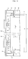
- a submerged membrane separator is submerged in a treatment tank and separates activated sludge and treated water as shown in FIG. 21 .
- the submerged membrane separator 1 includes a box-type casing 2 opened at the top and the bottom, a plurality of membrane cartridges 3 arrayed in parallel to one another in the casing 2, and an air diffuser 4 provided below the membrane cartridges 3.
- the membrane cartridges 3 have filtration plates 12 and filtration membranes 13 attached to both sides of the filtration membranes 12.
- the air diffuser 4 is configured to diffuse air from a diffusion pipe.
- a pressing plate 5 for preventing lifting of the membrane cartridges 3 is attached to the upper part of the casing 2.
- upflow 17 is caused among the membrane cartridges 3 by bubbles of the air diffused from the air diffuser 4. Matters adhering to the membrane surfaces of the membrane cartridges 3 are removed by this upflow 17. At this point, an upward force acts on the membrane cartridges 3 due to the upflow 17. However, the membrane cartridges 3 can be prevented from being lifted owing to the pressing plate 5.
- a pressing plate 6 is formed by a tabular supporting portion 7 and a comb-like pressing portion 8 of an elastic material bonded to the tabular supporting portion 7.
- the tabular supporting portion 7 is fixed to the upper end surface of the casing 2 by a bolt 9 and a nut 10.
- the comb-like pressing portion 8 has a plurality of protrusions 8a. The protrusions 8a are pressed into spaces between the membrane cartridges 3.
- the membrane cartridges 3 are pressed from above by the pressing plate 6 and are immovably secured. Therefore, it is possible to prevent vibrations of the membrane cartridges 3.
- the submerged membrane separator including the pressing plate as explained is described in, for example, Japanese Patent Application Laid-Open No. H10-137556 .
- the membrane cartridges 3 are forcibly pressed by the pressing plate 6 against a force to cause vibrations. Therefore, when the force to cause vibrations becomes excessively large, it is likely that the filtration plates 12 of the membrane cartridges 3 break.
- a first invention is a submerged membrane separator including: a casing opened at the top, a plurality of flat membrane cartridges arrayed at intervals in the casing, an air diffuser provided below the membrane cartridges, wherein the membrane cartridges are movably held in the up-down direction in the casing while having a space in the up-down direction, a lifting suppressing member for restricting a lifting amount of the membrane cartridges during a filtration operation to be smaller than the space in the up-down direction is provided in the casing, the separator is arranged such that during the filtration operation, an upflow is generated among the membrane cartridges by bubbles of air diffused from the air diffuser and an upward force acts on the membrane cartridges due to the upflow and the membrane cartridges are liftable with the upward force where the lifting amount of the membrane cartridges is restricted by the lifting suppressing member to be smaller than the space in the up-down direction, and a portion of the lifting suppressing member that comes into contact with the membrane cartridges is an elastic member, upper
- the lifting amount of the membrane cartridges is restricted by the lifting suppressing member to be smaller than the space in the up-down direction. Consequently, the membrane cartridges actively vibrate while being kept in a state in which the membrane cartridges are lifted within the range of the space in the up-down direction. Therefore, a cleaning effect for the membrane surfaces of the membrane cartridges is improved. Further, a contact portion between the membrane cartridges and a member fixed on the casing side is reduced, so that the abrasion of the membrane cartridges is reduced.
- the lifting amount of the membrane cartridges is restricted to be smaller than the space in the up-down direction owing to the lifting suppressing member.
- the membrane cartridges are movably held in the array direction of the membrane cartridges in the casing.
- the lifting suppressing member restricts the lifting amount of the membrane cartridges in the side portion of the membrane cartridges.
- the lifting suppressing member restricts the lifting amount of the membrane cartridges in the lower and/or the upper side portion of the membrane cartridges.
- the lifting suppressing member holds spaces between the membrane cartridges.
- a fitting portion is provided in the side portion of the membrane cartridges, and the lifting suppressing member fits in the fitting portion.
- an engaging portion is provided in the side portion of the membrane cartridges, and the engaging portion engages with the lifting suppressing member from below during a filtration operation.
- the lifting suppressing member is attached to the frame body of the casing or to a side panel that surrounds both sides of the membrane cartridges.
- the lifting amount of the membrane cartridges is restricted to be smaller than the space in the up-down direction by the lifting suppressing member. Therefore, the membrane cartridges actively vibrate while being kept in a state in which the membrane cartridges are lifted within the range of the space in the up-down direction. Consequently, the cleaning effect for the membrane surfaces of the membrane cartridges is improved.
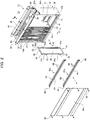
- FIGS. 1 to 9 A first embodiment in the present invention is explained below with reference to FIGS. 1 to 9 .
- reference numeral 31 denotes a submerged membrane separator.
- This submerged membrane separator 31 is submerged in a treatment tank 32 and separates raw water containing activated sludge and treated water.
- the submerged membrane separator 31 includes a box-type casing 33 for membranes opened at the top and the bottom, a plurality of flat membrane cartridges 34 arrayed in parallel and opposed to one another in the casing 33 for membranes, and an air diffuser 36 provided below these membrane cartridges 34.
- the air diffuser 36 is an example of a flow generating device.
- the air diffuser 36 diffuses air from a plurality of diffusing holes formed in an air diffusion pipe to thereby generate upflow 77 along the membrane surfaces of the membrane cartridges 34.
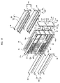
- the casing 33 for membranes includes a frame body 37, a pair of front and rear end covers 38 for covering both front and rear ends of the frame body 37, and a pair of left and right side panels 39a and 39b detachably attached to both sides of the frame body 37.
- the frame body 37 includes a bottom frame 41 having a square frame shape, an upper frame 42 having a square frame shape, and a plurality of vertical frames 43a and 43b coupled between the four corners of both the frames 41 and 42.
- Side openings 45a and 45b through which the membrane cartridge 34 can be removed and inserted in a width direction A are formed on both left and right sides of the frame body 37.
- the one side panel 39a is attached to the frame body 37 by a plurality of bolts 46 and closes the one side opening 45a.
- the other side panel 39b is attached to the frame body 37 by a plurality of bolts 46 and closes the other side opening 45b.
- the bolts 46 are unscrewed and the one side panel 39a is removed from the frame body 37, the one side opening 45a is opened.
- the other side opening 45b is opened.
- each of the membrane cartridges 34 includes a flat filtration plate 49 formed in a rectangular shape in the up-down direction, filtration membranes 50 attached to both front and rear sides of the filtration plate 49, and a plurality of side plates 51a and 51b (an example of side portions).
- the peripheral edges of the filtration membranes 50 are welded to the filtration plate 49 by ultrasound or the like, whereby the filtration membranes 50 are attached to the filtration plate 49.
- the upper and lower side plates 51a and 51b are provided in pairs on both sides of the filtration plate 49 in the width direction A, and project to the outer side.
- Recesses 52 having a square shape are formed in the side plates 51a and 51b.
- Water intake nozzles 53 (an example of water intake portions) for sucking treated water obtained by the filtration membranes 50 are provided at upper ends on both sides orthogonal to the width direction A of the filtration plate 49.
- Permeate channels (not shown) that communicate with the water intake nozzles 53 are respectively formed on both front and rear sides of the filtration plate 49. The permeate channels are covered with the filtration membranes 50.
- a pair of left and right water collecting pipes 55 for collecting treated water sucked from the water intake nozzles 53 of the membrane cartridges 34 are provided in the front-rear direction on the outer sides on the left and right of the upper frame 42 of the frame body 37.
- the water collecting pipes 55 and the water intake nozzles 53 are connected via connection pipes 56 having flexibility.
- upper guiding members 70 and lower guiding members 71 for guiding the membrane cartridges 34 in the width direction A are provided in the inside of the casing 33 for membranes.
- the left and right upper guiding members 70 are provided in pairs in the upper frame 42 of the frame body 37.
- the left and right lower guiding members 71 are provided in pairs in the bottom frame 41.
- a plurality of front and rear guiding grooves 72 are formed in each of the upper and lower guiding members 70 and 71.
- the upper ends of the membrane cartridges 34 are freely inserted into and removed from the guiding grooves 72 of the upper guiding member 70 from the width direction A (left-right direction).
- the lower ends of the membrane cartridges 34 are freely inserted into and removed from the guiding grooves 72 of the lower guiding member 71 from the width direction A (left-right direction).
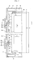
- left and right lifting suppressing members 63a and 63b are provided in pairs in upper and lower places in the casing 33 for membranes. As shown in FIGS. 5 and 6 , these lifting suppressing members 63a and 63b restrict a lifting amount of the membrane cartridges 34 during a filtration operation to be smaller than the space ⁇ in the up-down direction (i.e., 0 ⁇ lifting amount ⁇ space ⁇ ).
- the lifting suppressing members 63a and 63b include horizontal frames 64 and suppressing bodies 65 provided in the horizontal frames 64.
- the horizontal frames 64 are angle-shaped members having vertical plate portions 64a and horizontal plate portions 64b. Both ends of the horizontal frame 64 are detachably coupled between the front and rear vertical frames 43a and 43b by bolts 66 and nuts 67.
- the suppressing bodies 65 are portions that come into contact with the side plates 51a and 51b of the membrane cartridges 34.
- the material of the suppressing bodies 65 is an elastic body such as rubber.
- Grooves 68 are formed over the entire length on the outer surfaces of the suppressing bodies 65.
- a plurality of front and rear V-shaped slits 69 are formed on the inner surfaces of the suppressing bodies 65.
- the horizontal plate portions 64b of the horizontal frames 64 are inserted into the grooves 68 of the suppressing bodies 65, whereby the suppressing bodies 65 are attached to the horizontal frames 64.
- the slits 69 of the suppressing bodies 65 fit in the recesses 52 of the side plates 51a and 51b of the membrane cartridges 34.
- the membrane cartridges 34 are supported by the lifting suppressing members 63a and 63b, and a space S in the array direction C between the membrane cartridges 34 is maintained at a predetermined space.
- the recesses 52 and the slits 69 are fit without backlashing in the width direction A (left-right direction), the up-down direction B, and the array direction C (front-rear direction).
- the upflow 77 is generated among the membrane cartridges 34 by bubbles of the air diffused from the air diffuser 36. Matters adhering to the membrane surface deposits of the membrane cartridges 34 (sludge, etc.) are removed by the upflow 77.
- the upflow 77 smoothly flows without hitting the connection pipes 56. Therefore, matters adhering to the membrane surfaces of the membrane cartridges 34 are sufficiently removed. Since the upflow 77 does not hit the connection pipes 56, vibration of the connection pipes 56 is reduced and it is possible to prevent a crack from occurring around the water intake nozzles 53.
- an upward force acts on the membrane cartridges 34 due to the upflow 77 and buoyancy.
- the suppressing bodies 65 (a portion of the elastic body) of the lifting suppressing members 63a and 63b are elastically deformed by this upward force. As indicated by a virtual line in FIG. 7 , the membrane cartridge 34 lifts upward from the lower inner surface 71a of the guiding groove 72 of the lower guiding member 71.
- the lifting amount of the membrane cartridges 34 is restricted by the lifting suppressing members 63a and 63b to be smaller than the space ⁇ in the up-down direction B.
- the lifting amount of the membrane cartridges 34 is restricted to 3 mm.
- the space ⁇ and the lifting amount of the membrane cartridges 34 are not limited to the numerical values.
- the membrane cartridges 34 vibrate actively and minutely while being kept in a state in which the membrane cartridges 34 are lifted within the range of the space ⁇ in the up-down direction B. Therefore, a cleaning effect for the membrane surfaces of the membrane cartridges 34 is improved. Further, a contact portion between the membrane cartridges 34 and the upper guiding members 70 fixed to the casing 33 is reduced and a contact portion between the membrane cartridges 34 and the lower guiding members 71 fixed to the casing 33 is reduced. Therefore, the abrasion of the membrane cartridges 34 is reduced.
- the minute vibration of the membrane cartridges 34 occurs in the width direction A (left-right direction), the up-down direction B, and the array direction C (front-rear direction).
- the lower end of the membrane cartridge 34 comes into contact with and is supported by the lower inner surface 71a of the guiding groove 72 of the lower guiding member 71.
- the space ⁇ in the up-down direction B is formed between the upper end of the membrane cartridge 34 and the upper inner surface 70a of the guiding groove 72 of the upper guiding member 70.
- the bolts 46 are unscrewed to remove the one side panel 39a from the frame body 37 and open the one side opening 45a.
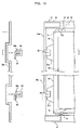
- the bolts 66 are unscrewed to remove the left or right one lifting suppressing member 63a from the frame body 37. Consequently, as shown in FIGS. 8 and 9B , the left or right one side plate 51a of the membrane cartridge 34 disengages from the slit 69 of the left or right one space suppressing member 63a. Thereafter, as indicated by virtual lines in FIGS. 2 and 8 , the membrane cartridge 34 can be pulled out from the inside of the casing 33 in the width direction A of the membrane cartridge 34 through the one side opening 45a, and taken out to the outer side of the casing 33.
- the recesses 52 of the left or right other side plate 51b of the membrane cartridge 34 disengage from the slits 69 of the left or right other lifting suppressing member 63b.
- the membrane cartridge 34 is pulled out in the width direction A while being guided by the upper and lower guiding grooves 72.
- the bolts 66 are screwed to attach the left or right one lifting suppressing member 63a to the vertical frame 43a on one of the left and right of the frame body 37. Consequently, as shown in FIGS. 7 and 9A , the recess 52 of the left or right one side plate 51a of the membrane cartridge 34 fits into the slit 69 of the left or right one lifting suppressing member 63a.
- the bolts 46 are screwed to attach the one side panel 39a to the frame body 37 to close the one side opening 45a. Consequently, the membrane cartridge 34 is housed and held in the inside of the casing 33.
- the one side opening 45a of the casing 33 for membranes is closed by the one side panel 39a and the other side opening 45b is closed by the other side panel 39b, during the filtration operation, it is possible to prevent bubbles of the air diffused from the air diffuser 36 from being released to the outside of the casing 33 through the side openings 45a and 45b.
- the one side panel 39a and one lifting suppressing member 63a are removed from the frame body 37 to open the one side opening 45a and remove the membrane cartridge 34 from and insert the membrane cartridge 34 into the casing 33 through the one side opening 45a.
- the other side panel 39b and the other lifting suppressing member 63b may be removed from the frame body 37 to remove the membrane cartridge 34 from and insert the membrane cartridge 34 into the casing 33 through the other side opening 45b.
- the left and right water intake nozzles 53 are provided in pairs in the membrane cartridge 34 and the left and right water collecting pipes 55 are provided in pairs in the frame body 37.
- the left and right water intake nozzles 53 may be provided and only one of the left and right water collecting pipes 55 may be provided.
- the suppressing bodies 65 of the lifting suppressing members 63a and 63b have the slits 69.
- suppressing bodies 65 do not have slits 69.
- the suppressing bodies 65 fit in recesses 52 of side plates 51a and 51b of membrane cartridges 34.
- the left and right side plates 51a and 51b are provided in pairs in the upper and lower places of the membrane cartridge 34.
- the side plates 51a and 51b may be provided in a plurality of places or only one place other than the upper and lower places.
- the left and right lifting suppressing members 63a and 63b are provided in pairs in the upper and lower places in the inside of the casing 33.
- the lifting suppressing members 63a and 63b may be provided in a plurality of places or only one place other than the upper and lower places.
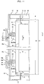
- a membrane cartridge 34 has a plurality of engaging plates 80a and 80b (an example of engaging portions).
- the upper and lower engaging plates 80a and 80b are provided in pairs on both sides in the width direction A of a filtration plate 49 and project to the outer side.
- One of the left and right engaging plates 80a engages with a suppressing body 65 of one of left and right lifting suppressing members 63a from below.
- the other one of the left and right engaging plates 80b engages with the suppressing body 65 of the other one of left and right lifting suppressing members 63b from below.
- the lifting amount of the membrane cartridge 34 is restricted by the lifting suppressing members 63a and 63b to be smaller than a space ⁇ in an up-down direction B. Consequently, the membrane cartridge 34 vibrates actively and minutely while being kept in a state in which the membrane cartridge 34 is lifted within the range of the space ⁇ in the up-down direction B. Therefore, a cleaning effect for the membrane surface of the membrane cartridge 34 is improved. Further, a contact portion between the membrane cartridge 34 and an upper guiding member 70 fixed to a casing 33 is reduced and a contact portion between the membrane cartridge 34 and the lower guiding member 71 fixed to the casing 33 is reduced. Therefore, the abrasion of the membrane cartridge 34 is reduced.
- the left and right engaging plates 80a and 80b are provided in pairs in the upper and lower places of the membrane cartridge 34.
- the engaging plates 80a and 80b may be provided in a plurality of places or only one place other than the upper and lower places.
- the left and right lifting suppressing members 63a and 63b are provided in pairs in the upper and lower places in the inside of the casing 33.
- the lifting suppressing members 63a and 63b may be provided in a plurality of places or only one place other than the upper and lower places.
- the lifting suppressing members 63a and 63b are provided in a frame body 37.
- one of the left and right lifting suppressing members 63a may be provided on the inner surface of one side panel 39a and the other one of the left and right lifting suppressing members 63b may be provided on the inner surface of the other side panel 39b.
- the membrane cartridges 34 are set in contact with the lifting suppressing members 63a and 63b.
- the membrane cartridges 34 may be separated from the lifting suppressing members 63a and 63b without being in contact with the lifting suppressing members 63a and 63b, and when the filtration operation, is carried out, the membrane cartridges 34 may be set in contact with the lifting suppressing members 63a and 63b.
- FIGS. 12 and 13 Next, a fourth embodiment in the present invention is explained with reference to FIGS. 12 and 13 .
- a membrane cartridge 34 has a plurality of lower engaging projecting portions 82 (an example of engaging portions). These lower engaging projecting portions 82 are provided on both sides of the lower side of a filtration plate 49 and project in an array direction C.
- each of the lifting suppressing members 84 includes a bottom plate portion 85, a plurality of vertical plate portions 86 erected upward from the bottom plate portion 85, and projecting portions 87 to be engaged projecting in the array direction C from the upper ends of the vertical plate portions 86.
- the lower engaging projecting portion 82 is removably insertable into a width direction A between the vertical plate portions 86 opposed to each other in the array direction C.
- the filtration plate 49 is removably insertable into the width direction A between the projecting portions 87 to be engaged opposed to each other in the array direction C.
- the lower engaging projecting portion 82 engages with the projecting portion 87 to be engaged from below.
- the upper ends of the membrane cartridges 34 are inserted into grooves 72 of upper guiding members 70. Further, as in the first embodiment, the membrane cartridges 34 are held in the inside of a casing 33 in a state in which the membrane cartridges 34 have a space ⁇ in an up-down direction B.
- a vertical space from the bottom plate portion 85 to the projecting portions 87 to be engaged is larger than the vertical thickness of the lower engaging projecting portions 82.
- a space ⁇ is formed between the projecting portions 87 to be engaged and the lower engaging projecting portions 82. This space ⁇ is set smaller than the space ⁇ .
- the lifting amount of the membrane cartridges 34 is restricted by the lifting suppressing member 84 to an amount equivalent to the space ⁇ smaller than the space ⁇ in the up-down direction B. Consequently, the membrane cartridges 34 vibrate actively and minutely while being kept in a state in which the membrane cartridges 34 are lifted within the range of the space ⁇ . Therefore, a cleaning effect for the membrane surfaces of the membrane cartridges 34 is improved. A contact portion between the membrane cartridges 34 and the upper guiding member 70 fixed to a casing 33 is reduced and the abrasion of the membrane cartridges 34 is reduced.
- the membrane cartridges 34 sink with own weight 78, the lower ends of the membrane cartridges 34 are supported by the bottom plate portion 85 of the lifting suppressing member 84, and the space ⁇ in the up-down direction B is formed between the upper ends of the membrane cartridges 34 and upper inner surfaces 70a of the guiding grooves 72 of the upper guiding member 70.
- Lifting suppressing members 88 restrict a lifting amount with respect to the upper side of a membrane cartridge 34.
- the lifting suppressing members 88 have a comb-tooth structure including a plurality of guide grooves 72.
- the left and right lifting suppressing members 88 are provided in pairs in an upper frame 42.
- a space S among the membrane cartridges 34 is kept at a predetermined space by space maintaining members 89.
- the space maintaining members 89 have a plurality of front and rear V-shaped slits 69.
- the slits 69 of the space maintaining members 89 fit in recesses 52 of side plates 51a and 51b of the membrane cartridges 34. Consequently, the space S in the array direction C among the membrane cartridges 34 is maintained at the predetermined space.
- an upward force acts on the membrane cartridges 34 with upflow 77 and buoyancy.
- the membrane cartridges 34 are lifted upward.
- the upper ends of the membrane cartridges 34 come into contact with upper inner surfaces 70a of the guiding grooves 72 of the lifting suppressing member 88.
- a space is formed between the lower ends of the membrane cartridges 34 and lower inner surfaces 71a of the guiding grooves 72 of a lower guiding member 71.
- the lifting amount of the membrane cartridges 34 is restricted to an amount equivalent to a space ⁇ in an up-down direction B. Consequently, the membrane cartridges 34 vibrate actively and minutely while being kept in a state in which the membrane cartridges 34 are lifted. Therefore, a cleaning effect for the membrane surfaces of the membrane cartridges 34 is improved.
- the sixth embodiment is a modification of the first embodiment.
- Left and right side plates 51a and 51b of a membrane cartridge 34 are provided in a pair in positions lower than the center of gravity G of the membrane cartridge 34.
- left and right lifting suppressing members 63a and 63b are also provided in a pair in positions lower than a center of gravity G of the membrane cartridge 34.
- the membrane cartridge 34 minutely vibrates while being kept in a state in which the membrane cartridge 34 is lifted within the range of a space ⁇ in an up-down direction B by upflow 77 generated when air diffusion is performed from an air diffuser 36.
- the side plates 51a and 51b of the membrane cartridge 34 and the lifting suppressing members 63a and 63b are respectively provided in the positions lower than the center of gravity G of the membrane cartridge 34, the vibration of the membrane cartridge 34 is facilitated.
- the side plates 51a and 51b of the membrane cartridge 34 and the lifting suppressing members 63a and 63b are respectively provided in the positions lower than the center of gravity G of the membrane cartridge 34.
- the side plates 51a and 51b of the membrane cartridge 34 and the lifting suppressing members 63a and 63b may be provided in positions at the same height as the center of gravity G of the membrane cartridge 34.
- a filtration membrane 50 of a membrane cartridge 34 is divided into upper and lower portions 91 and 92.
- a boundary portion where the upper portion 91 and the lower portion 92 are adjacent to each other is welded to a filtration plate 49. Consequently, a welded portion 93 is formed over the entire width of the filtration membrane 50 in the boundary portion in the vertical center of the filtration membrane 50.
- Two water intake nozzles 53a and 53b for sucking treated water obtained by the membrane filtration 50 are provided in the filtration plate 49.
- the upper water intake nozzle 53a is provided on one of the left and right sides of the filtration plate 49 and at the upper end of the upper portion 91.
- the lower water intake nozzle 53b is provided on one of the left and right sides of the filtration plate 49 and at the upper end of the lower portion 92.
- Upper and lower water collecting pipes 55a and 55b for collecting treated water sucked from the water intake nozzles 53a and 53b are provided in a pair on one side of a frame body 37 of a casing 33.
- the upper water collecting pipe 55a and the upper water intake nozzle 53a are connected via a connection pipe 56 and the lower water collecting pipe 55b and the lower water intake nozzle 53b are connected via the connection pipe 56.
- Both side covers 39a and 39b are respectively divided into two as an upper side cover body 97 and a lower side cover body 98.
- the upper and lower side cover bodies 97 and 98 are respectively detachably attached to the frame body 37 by bolts 46.
- the inner side of the membrane cartridge 34 is depressurized while air diffusion is performed from an air diffuser 36, whereby sludge or the like in a liquid to be treated 47 is caught by the filtration membrane 50 of the membrane cartridge 34.
- Permeate permeating through the filtration membrane 50 and flowing into the inner side of the membrane cartridge 34 is collected in the water collecting pipes 55a and 55b from the water intake nozzles 53a and 53b through the connection pipes 56.
- upflow 77 is generated among the membrane cartridges 34 by bubbles of air diffused from the air diffuser 36. Matters adhering to the membrane surfaces of the membrane cartridges 34 are removed by the upflow 77.
- the upper water intake nozzle 53a is provided at the upper end of the upper portion 91 and the lower water intake nozzle 53b is provided at the upper end of the lower portion 92. Therefore, it is possible to surely collect treated water from the entire region in the portions 91 and 92 and prevent air pocket from occurring in the portions 91 and 92.
- the filtration membrane 50 vibrates in the thickness direction with respect to the filtration plate 49 due to the force of the upflow 77.
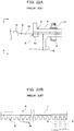
- the height L of the filtration membrane 50 is divided vertically into upper and lower halves (i.e., L/2) by the portions 91 and 92. Therefore, a width W1 of the filtration membrane 50 vibrating in the thickness direction in each of the portions 91 and 92 is small compared with a width W2 of the filtration membrane 50, in which the portions 91 and 92 are not formed as shown in FIG. 19B , vibrating in the thickness direction (M1 ⁇ W2).
- FIGS. 19A and 19B exaggeratingly indicate a state in which the filtration membrane 50 vibrates. Actually, the widths W1 and W2 of vibration of the filtration membrane 50 are extremely small.
- the filtration membrane 50 is divided into the two portions 91 and 92 by welding the vertical center of the filtration membrane 50 to the filtration plate 49 over the entire width.
- the filtration membrane 50 may be divided into the two portions 91 and 92 by providing ribs in the filtration plate 49.
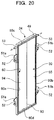
- the filtration membrane 50 is divided into the upper and lower portions 91 and 92. However, the filtration membrane 50 may be divided vertically into three or more portions. As an eighth embodiment, as shown in FIG. 20 , the filtration membrane 50 may be divided into left and right portions 94 and 95 or may be divided horizontally into three or more portions.
Landscapes
- Chemical & Material Sciences (AREA)
- Chemical Kinetics & Catalysis (AREA)
- Engineering & Computer Science (AREA)
- Water Supply & Treatment (AREA)
- Life Sciences & Earth Sciences (AREA)
- Biodiversity & Conservation Biology (AREA)
- Microbiology (AREA)
- Hydrology & Water Resources (AREA)
- Environmental & Geological Engineering (AREA)
- Organic Chemistry (AREA)
- Separation Using Semi-Permeable Membranes (AREA)
Claims (10)
- Tauchmembranabscheider (31), umfassend:ein oben offenes Gehäuse (33);mehrere Flachmembraneinsätze (34), die in Abständen in dem Gehäuse (33) angeordnet sind;einen Luftdiffusor (36), der unter den Membraneinsätzen (34) vorgesehen ist;wobei die Membraneinsätze (34) in einer von oben nach unten verlaufenden Richtung (B) im Gehäuse (33) beweglich gehalten werden, während sie in der von oben nach unten verlaufenden Richtung (B) einen Raum (α) aufweisen,ein Hubunterdrückungsglied (63a, 63b) zum Beschränken eines Hubausmaßes der Membraneinsätze (34) während eines Filtrationsvorgangs, so dass es kleiner als der Raum (α) in der von oben nach unten verlaufenden Richtung (B) ist, in dem Gehäuse (33) vorgesehen ist;der Abscheider (31) so angeordnet ist, dass während des Filtrationsvorgangs zwischen den Membraneinsätzen (34) durch von dem Luftdiffusor (36) verteilte Luftblasen eine Aufwärtsströmung erzeugt wird und aufgrund der Aufwärtsströmung eine Aufwärtskraft auf die Membraneinsätze (34) wirkt und die Membraneinsätze (34) mit der Aufwärtskraft anhebbar sind, wobei das Hubausmaß der Membraneinsätze (34) durch das Hubunterdrückungsglied (63a, 63b) so beschränkt wird, dass es kleiner als der Raum (α) in der von oben nach unten verlaufenden Richtung (B) ist;dadurch gekennzeichnet, dassein Teil des Hubunterdrückungsglieds (63a, 63b), das mit den Membraneinsätzen (34) in Kontakt kommt, ein elastisches Glied (65) ist, undobere Führungsglieder (70) und untere Führungsglieder (71) zum Führen der Membraneinsätze (34) in der Breitenrichtung (A) im Inneren des Gehäuses (33) vorgesehen sind, die linken und rechten oberen Führungsglieder (70) in Paaren in einem oberen Rahmen (42) eines Rahmenkörpers (37) vorgesehen sind und die linken und rechten unteren Führungsglieder (71) in Paaren im unteren Rahmen (41) vorgesehen sind;mehrere vordere und hintere Führungsnuten (72) in jedem der oberen und unteren Führungsglieder (70, 71) ausgebildet sind, wobei die oberen Enden der Membraneinsätze (34) aus der Breitenrichtung (A) frei in die Führungsnuten (72) des oberen Führungsglieds (70) eingeführt und daraus entfernt werden und die unteren Enden der Membraneinsätze (34) aus der Breitenrichtung (A) frei in die Führungsnuten (72) des unteren Führungsglieds (71) eingeführt und daraus entfernt werden;wobei die Höhe H1 zwischen einer oberen Innenfläche (70a) der Führungsnut (72) des oberen Führungsglieds (70) und einer unteren Innenfläche (71a) der Führungsnut (72) des unteren Führungsglieds (71) größer eingestellt ist als eine Höhe H2 des Membraneinsatzes (34), so dass der Raum (α) in der von oben nach unten verlaufenden Richtung (B) als α = H1-H2 definiert ist.
- Tauchmembranabscheider (31) nach Anspruch 1, dadurch gekennzeichnet, dass die Membraneinsätze (34) in einer Anordnungsrichtung (C) der Membraneinsätze (34) in dem Gehäuse (33) beweglich gehalten werden.
- Tauchmembranabscheider (31) nach Anspruch 1 oder 2, dadurch gekennzeichnet, dass das Hubunterdrückungsglied (63a, 63b) das Hubausmaß der Membraneinsätze (34) in einem Seitenteil (51a, 51b) der Membraneinsätze (34) beschränkt.
- Tauchmembranabscheider (31) nach Anspruch 1 oder 2, dadurch gekennzeichnet, dass das Hubunterdrückungsglied (63a, 63b) das Hubausmaß der Membraneinsätze (34) in einem unteren Seitenteil (51a, 51b) der Membraneinsätze (34) beschränkt.
- Tauchmembranabscheider (31) nach Anspruch 1 oder 2, dadurch gekennzeichnet, dass das Hubunterdrückungsglied (63a, 63b) das Hubausmaß der Membraneinsätze (34) in einem oberen Seitenteil (51a, 51b) der Membraneinsätze (34) beschränkt.
- Tauchmembranabscheider (31) nach einem der Ansprüche 1 bis 5, dadurch gekennzeichnet, dass das Hubunterdrückungsglied (63a, 63b) Räume (S) zwischen den Membraneinsätzen (34) aufrechterhält.
- Tauchmembranabscheider (31) nach Anspruch 3, dadurch gekennzeichnet, dass
ein Anordnungsteil (52) im Seitenteil der Membraneinsätze (34) vorgesehen ist, und
das Hubunterdrückungsglied (63a, 63b) in den Anordnungsteil (52) angeordnet ist. - Tauchmembranabscheider (31) nach Anspruch 3, dadurch gekennzeichnet, dass ein Eingriffsteil (80a, 80b) im Seitenteil (51a, 51b) der Membraneinsätze (34) vorgesehen ist, und der Eingriffsteil (80a, 80b) während eines Filtrationsvorgangs mit dem Hubunterdrückungsglied (63a, 63b) in Eingriff steht.
- Tauchmembranabscheider (31) nach einem der Ansprüche 1 bis 8, dadurch gekennzeichnet, dass das Hubunterdrückungsglied (63a, 63b) an einem Rahmenkörper (37) des Gehäuses (33) befestigt ist.
- Tauchmembranabscheider (31) nach Anspruch 3, dadurch gekennzeichnet, dass das Hubunterdrückungsglied (63a, 63b) an einer Seitenplatte (39a, 39b befestigt ist, die beide Seiten der Membraneinsätze (34) umgibt.
Applications Claiming Priority (2)
| Application Number | Priority Date | Filing Date | Title |
|---|---|---|---|
| JP2007321441A JP5264159B2 (ja) | 2007-12-13 | 2007-12-13 | 浸漬型膜分離装置 |
| PCT/JP2008/003485 WO2009075067A1 (ja) | 2007-12-13 | 2008-11-27 | 浸漬型膜分離装置 |
Publications (3)
| Publication Number | Publication Date |
|---|---|
| EP2223736A1 EP2223736A1 (de) | 2010-09-01 |
| EP2223736A4 EP2223736A4 (de) | 2012-08-22 |
| EP2223736B1 true EP2223736B1 (de) | 2019-05-08 |
Family
ID=40755317
Family Applications (1)
| Application Number | Title | Priority Date | Filing Date |
|---|---|---|---|
| EP08860780.9A Active EP2223736B1 (de) | 2007-12-13 | 2008-11-27 | Tauchmembranabscheider |
Country Status (5)
| Country | Link |
|---|---|
| US (1) | US8821726B2 (de) |
| EP (1) | EP2223736B1 (de) |
| JP (1) | JP5264159B2 (de) |
| CN (1) | CN101896252B (de) |
| WO (1) | WO2009075067A1 (de) |
Families Citing this family (20)
| Publication number | Priority date | Publication date | Assignee | Title |
|---|---|---|---|---|
| JP5566031B2 (ja) * | 2009-01-06 | 2014-08-06 | 株式会社クボタ | 間隔保持部材および膜エレメントおよび浸漬型膜分離装置 |
| JP5627324B2 (ja) * | 2010-07-21 | 2014-11-19 | クボタメンブレン株式会社 | 収納ケース、搬送台車および浸漬型膜分離装置 |
| USD648007S1 (en) * | 2010-08-02 | 2011-11-01 | Asahi Kasei Chemicals Corporation | Air diffusion pipe for a filter |
| USD648009S1 (en) * | 2010-08-05 | 2011-11-01 | Asahi Kasei Chemicals Corporation | Pipe for a filter |
| JP5691487B2 (ja) * | 2010-12-20 | 2015-04-01 | 三菱レイヨン株式会社 | 中空糸膜モジュールユニット |
| KR102077361B1 (ko) * | 2012-11-27 | 2020-02-13 | 도레이 카부시키가이샤 | 분리막 모듈 |
| DK178140B1 (en) * | 2014-02-03 | 2015-06-22 | Sani Membranes Aps | Filter plate assembly |
| DE102014113497B4 (de) * | 2014-09-18 | 2018-06-28 | Sartorius Stedim Biotech Gmbh | Filtrationsmodul und Verfahren zur Herstellung |
| JP5880666B2 (ja) * | 2014-11-14 | 2016-03-09 | 三菱レイヨン株式会社 | 中空糸膜モジュールユニット |
| JP6627872B2 (ja) * | 2015-06-08 | 2020-01-08 | 住友電気工業株式会社 | 濾過装置 |
| CN106975361B (zh) * | 2017-04-14 | 2022-09-06 | 广东创源节能环保有限公司 | 一种立式卷式膜振动过滤装置 |
| DK180105B1 (en) | 2018-03-08 | 2020-05-04 | Sani Membranes Aps | A filter-plate with external flow area |
| CN108525522B (zh) * | 2018-06-20 | 2023-11-10 | 邢传宏 | 一种平膜元件用支撑元件及平膜元件 |
| KR20210132921A (ko) * | 2020-04-28 | 2021-11-05 | 주식회사 아모그린텍 | 중력식 정수장치용 필터모듈 및 이를 포함하는 중력식 정수장치 |
| EP4026608A1 (de) * | 2021-01-08 | 2022-07-13 | Ovivo Inc. | Mechanische unterstützung für verbesserte membranleistung und -zuverlässigkeit |
| CN112999880B (zh) * | 2021-03-04 | 2021-12-14 | 苏州苏科环保科技有限公司 | 浸没式膜过滤装置 |
| JP7392752B2 (ja) * | 2022-03-23 | 2023-12-06 | 株式会社明電舎 | 濾過システムおよび濾過処理設備 |
| CN115212725B (zh) * | 2022-07-27 | 2023-08-18 | 东风柳州汽车有限公司 | 滤膜重复利用装置及过滤器 |
| JP2024061485A (ja) * | 2022-10-21 | 2024-05-07 | 株式会社エフ・シー・シー | 濾過膜ユニット |
| IT202300002535A1 (it) * | 2023-02-15 | 2024-08-15 | Giovambattista Greco | Sistema di micro-ultrafiltrazione con membrane tubolari |
Family Cites Families (10)
| Publication number | Priority date | Publication date | Assignee | Title |
|---|---|---|---|---|
| JPH03188926A (ja) * | 1989-12-19 | 1991-08-16 | Kubota Corp | ろ過処理方法 |
| JPH09276868A (ja) * | 1996-04-15 | 1997-10-28 | Kubota Corp | 浸漬型膜分離装置の浮上防止構造 |
| JP3328149B2 (ja) | 1996-11-18 | 2002-09-24 | 株式会社クボタ | 浸漬型膜分離装置 |
| JP3333116B2 (ja) * | 1997-08-08 | 2002-10-07 | 株式会社クボタ | 膜分離装置 |
| JP3536610B2 (ja) * | 1997-08-25 | 2004-06-14 | 栗田工業株式会社 | 浸漬型膜濾過装置 |
| JP2000005573A (ja) * | 1998-06-29 | 2000-01-11 | Kubota Corp | 浸漬型膜分離装置 |
| US7122121B1 (en) * | 2004-05-28 | 2006-10-17 | Jiang Ji | Advanced submerged membrane modules, systems and processes |
| US7297278B2 (en) * | 2004-10-20 | 2007-11-20 | Baker Hughes Incorporated | Methods for removing metals from water |
| AU2007242360B2 (en) * | 2006-03-27 | 2010-09-30 | Toray Industries, Inc. | Membrane element, membrane unit and multistage membrane unit |
| JP2008237960A (ja) | 2007-03-26 | 2008-10-09 | Toray Ind Inc | 膜エレメントおよび膜分離装置 |
-
2007
- 2007-12-13 JP JP2007321441A patent/JP5264159B2/ja active Active
-
2008
- 2008-11-27 EP EP08860780.9A patent/EP2223736B1/de active Active
- 2008-11-27 WO PCT/JP2008/003485 patent/WO2009075067A1/ja not_active Ceased
- 2008-11-27 US US12/746,949 patent/US8821726B2/en active Active
- 2008-11-27 CN CN2008801204992A patent/CN101896252B/zh active Active
Non-Patent Citations (1)
| Title |
|---|
| None * |
Also Published As
| Publication number | Publication date |
|---|---|
| CN101896252B (zh) | 2013-05-22 |
| JP5264159B2 (ja) | 2013-08-14 |
| EP2223736A1 (de) | 2010-09-01 |
| EP2223736A4 (de) | 2012-08-22 |
| US20100282655A1 (en) | 2010-11-11 |
| JP2009142732A (ja) | 2009-07-02 |
| US8821726B2 (en) | 2014-09-02 |
| CN101896252A (zh) | 2010-11-24 |
| WO2009075067A1 (ja) | 2009-06-18 |
Similar Documents
| Publication | Publication Date | Title |
|---|---|---|
| US8821726B2 (en) | Submerged membrane separator | |
| EP2228124B1 (de) | Tauch-filmkassettentrennvorrichtung | |
| JP5566031B2 (ja) | 間隔保持部材および膜エレメントおよび浸漬型膜分離装置 | |
| EP2260929A1 (de) | Membranelement und membranmodul | |
| US8647507B2 (en) | Membrane cartridge | |
| JP3536610B2 (ja) | 浸漬型膜濾過装置 | |
| CN101405073A (zh) | 膜元件、膜单元及多级叠加膜单元 | |
| JP5425394B2 (ja) | 濾過モジュール、濾過モジュール積層体、および濾過装置 | |
| JP2007111623A (ja) | 濾過ユニット | |
| JP2000157848A (ja) | 浸漬型膜分離装置 | |
| JP6570276B2 (ja) | 膜分離装置 | |
| JPH10263371A (ja) | 浸漬型濾過膜エレメント | |
| JP2013063381A (ja) | 浸漬型膜分離装置における膜ユニット | |
| JP5889694B2 (ja) | 浸漬型平膜エレメント及び浸漬型平膜エレメントを用いた膜ユニット | |
| CN105828918A (zh) | 膜分离装置 | |
| JP2014171984A (ja) | 浸漬型膜分離装置及び平膜エレメント | |
| JP2021074683A (ja) | 分離膜モジュール | |
| JP2022144472A (ja) | 分離膜モジュール | |
| JP5889693B2 (ja) | 浸漬型平膜エレメント及び浸漬型平膜エレメントを用いた膜ユニット | |
| JPH09276868A (ja) | 浸漬型膜分離装置の浮上防止構造 | |
| JP2010131538A (ja) | 浸漬型膜分離モジュールおよび平膜エレメントの交換方法 | |
| JP2022144470A (ja) | 分離膜モジュール | |
| JPH11319510A (ja) | 浸漬型膜分離装置 | |
| JP2006205074A (ja) | 濾過ユニット | |
| JP2002113335A (ja) | 膜モジュールおよび浸漬型膜分離装置 |
Legal Events
| Date | Code | Title | Description |
|---|---|---|---|
| PUAI | Public reference made under article 153(3) epc to a published international application that has entered the european phase |
Free format text: ORIGINAL CODE: 0009012 |
|
| 17P | Request for examination filed |
Effective date: 20100713 |
|
| AK | Designated contracting states |
Kind code of ref document: A1 Designated state(s): AT BE BG CH CY CZ DE DK EE ES FI FR GB GR HR HU IE IS IT LI LT LU LV MC MT NL NO PL PT RO SE SI SK TR |
|
| AX | Request for extension of the european patent |
Extension state: AL BA MK RS |
|
| DAX | Request for extension of the european patent (deleted) | ||
| A4 | Supplementary search report drawn up and despatched |
Effective date: 20120720 |
|
| RIC1 | Information provided on ipc code assigned before grant |
Ipc: C02F 1/44 20060101ALI20120716BHEP Ipc: B01D 65/08 20060101ALI20120716BHEP Ipc: B01D 63/08 20060101AFI20120716BHEP Ipc: C02F 3/12 20060101ALI20120716BHEP Ipc: B01D 61/18 20060101ALI20120716BHEP |
|
| STAA | Information on the status of an ep patent application or granted ep patent |
Free format text: STATUS: EXAMINATION IS IN PROGRESS |
|
| 17Q | First examination report despatched |
Effective date: 20171025 |
|
| GRAP | Despatch of communication of intention to grant a patent |
Free format text: ORIGINAL CODE: EPIDOSNIGR1 |
|
| STAA | Information on the status of an ep patent application or granted ep patent |
Free format text: STATUS: GRANT OF PATENT IS INTENDED |
|
| INTG | Intention to grant announced |
Effective date: 20181023 |
|
| GRAS | Grant fee paid |
Free format text: ORIGINAL CODE: EPIDOSNIGR3 |
|
| RAP1 | Party data changed (applicant data changed or rights of an application transferred) |
Owner name: KUBOTA CORPORATION |
|
| GRAA | (expected) grant |
Free format text: ORIGINAL CODE: 0009210 |
|
| STAA | Information on the status of an ep patent application or granted ep patent |
Free format text: STATUS: THE PATENT HAS BEEN GRANTED |
|
| AK | Designated contracting states |
Kind code of ref document: B1 Designated state(s): AT BE BG CH CY CZ DE DK EE ES FI FR GB GR HR HU IE IS IT LI LT LU LV MC MT NL NO PL PT RO SE SI SK TR |
|
| REG | Reference to a national code |
Ref country code: GB Ref legal event code: FG4D |
|
| REG | Reference to a national code |
Ref country code: CH Ref legal event code: EP Ref country code: AT Ref legal event code: REF Ref document number: 1129292 Country of ref document: AT Kind code of ref document: T Effective date: 20190515 |
|
| REG | Reference to a national code |
Ref country code: DE Ref legal event code: R096 Ref document number: 602008060044 Country of ref document: DE Ref country code: IE Ref legal event code: FG4D |
|
| REG | Reference to a national code |
Ref country code: NL Ref legal event code: MP Effective date: 20190508 |
|
| REG | Reference to a national code |
Ref country code: LT Ref legal event code: MG4D |
|
| PG25 | Lapsed in a contracting state [announced via postgrant information from national office to epo] |
Ref country code: HR Free format text: LAPSE BECAUSE OF FAILURE TO SUBMIT A TRANSLATION OF THE DESCRIPTION OR TO PAY THE FEE WITHIN THE PRESCRIBED TIME-LIMIT Effective date: 20190508 Ref country code: LT Free format text: LAPSE BECAUSE OF FAILURE TO SUBMIT A TRANSLATION OF THE DESCRIPTION OR TO PAY THE FEE WITHIN THE PRESCRIBED TIME-LIMIT Effective date: 20190508 Ref country code: NO Free format text: LAPSE BECAUSE OF FAILURE TO SUBMIT A TRANSLATION OF THE DESCRIPTION OR TO PAY THE FEE WITHIN THE PRESCRIBED TIME-LIMIT Effective date: 20190808 Ref country code: NL Free format text: LAPSE BECAUSE OF FAILURE TO SUBMIT A TRANSLATION OF THE DESCRIPTION OR TO PAY THE FEE WITHIN THE PRESCRIBED TIME-LIMIT Effective date: 20190508 Ref country code: SE Free format text: LAPSE BECAUSE OF FAILURE TO SUBMIT A TRANSLATION OF THE DESCRIPTION OR TO PAY THE FEE WITHIN THE PRESCRIBED TIME-LIMIT Effective date: 20190508 Ref country code: ES Free format text: LAPSE BECAUSE OF FAILURE TO SUBMIT A TRANSLATION OF THE DESCRIPTION OR TO PAY THE FEE WITHIN THE PRESCRIBED TIME-LIMIT Effective date: 20190508 Ref country code: PT Free format text: LAPSE BECAUSE OF FAILURE TO SUBMIT A TRANSLATION OF THE DESCRIPTION OR TO PAY THE FEE WITHIN THE PRESCRIBED TIME-LIMIT Effective date: 20190908 Ref country code: FI Free format text: LAPSE BECAUSE OF FAILURE TO SUBMIT A TRANSLATION OF THE DESCRIPTION OR TO PAY THE FEE WITHIN THE PRESCRIBED TIME-LIMIT Effective date: 20190508 |
|
| PG25 | Lapsed in a contracting state [announced via postgrant information from national office to epo] |
Ref country code: BG Free format text: LAPSE BECAUSE OF FAILURE TO SUBMIT A TRANSLATION OF THE DESCRIPTION OR TO PAY THE FEE WITHIN THE PRESCRIBED TIME-LIMIT Effective date: 20190808 Ref country code: LV Free format text: LAPSE BECAUSE OF FAILURE TO SUBMIT A TRANSLATION OF THE DESCRIPTION OR TO PAY THE FEE WITHIN THE PRESCRIBED TIME-LIMIT Effective date: 20190508 |
|
| REG | Reference to a national code |
Ref country code: AT Ref legal event code: MK05 Ref document number: 1129292 Country of ref document: AT Kind code of ref document: T Effective date: 20190508 |
|
| REG | Reference to a national code |
Ref country code: GR Ref legal event code: EP Ref document number: 20190402384 Country of ref document: GR Effective date: 20191128 |
|
| PG25 | Lapsed in a contracting state [announced via postgrant information from national office to epo] |
Ref country code: EE Free format text: LAPSE BECAUSE OF FAILURE TO SUBMIT A TRANSLATION OF THE DESCRIPTION OR TO PAY THE FEE WITHIN THE PRESCRIBED TIME-LIMIT Effective date: 20190508 Ref country code: DK Free format text: LAPSE BECAUSE OF FAILURE TO SUBMIT A TRANSLATION OF THE DESCRIPTION OR TO PAY THE FEE WITHIN THE PRESCRIBED TIME-LIMIT Effective date: 20190508 Ref country code: SK Free format text: LAPSE BECAUSE OF FAILURE TO SUBMIT A TRANSLATION OF THE DESCRIPTION OR TO PAY THE FEE WITHIN THE PRESCRIBED TIME-LIMIT Effective date: 20190508 Ref country code: AT Free format text: LAPSE BECAUSE OF FAILURE TO SUBMIT A TRANSLATION OF THE DESCRIPTION OR TO PAY THE FEE WITHIN THE PRESCRIBED TIME-LIMIT Effective date: 20190508 Ref country code: RO Free format text: LAPSE BECAUSE OF FAILURE TO SUBMIT A TRANSLATION OF THE DESCRIPTION OR TO PAY THE FEE WITHIN THE PRESCRIBED TIME-LIMIT Effective date: 20190508 Ref country code: CZ Free format text: LAPSE BECAUSE OF FAILURE TO SUBMIT A TRANSLATION OF THE DESCRIPTION OR TO PAY THE FEE WITHIN THE PRESCRIBED TIME-LIMIT Effective date: 20190508 |
|
| REG | Reference to a national code |
Ref country code: DE Ref legal event code: R097 Ref document number: 602008060044 Country of ref document: DE |
|
| PLBE | No opposition filed within time limit |
Free format text: ORIGINAL CODE: 0009261 |
|
| STAA | Information on the status of an ep patent application or granted ep patent |
Free format text: STATUS: NO OPPOSITION FILED WITHIN TIME LIMIT |
|
| PG25 | Lapsed in a contracting state [announced via postgrant information from national office to epo] |
Ref country code: TR Free format text: LAPSE BECAUSE OF FAILURE TO SUBMIT A TRANSLATION OF THE DESCRIPTION OR TO PAY THE FEE WITHIN THE PRESCRIBED TIME-LIMIT Effective date: 20190508 |
|
| 26N | No opposition filed |
Effective date: 20200211 |
|
| PG25 | Lapsed in a contracting state [announced via postgrant information from national office to epo] |
Ref country code: PL Free format text: LAPSE BECAUSE OF FAILURE TO SUBMIT A TRANSLATION OF THE DESCRIPTION OR TO PAY THE FEE WITHIN THE PRESCRIBED TIME-LIMIT Effective date: 20190508 |
|
| PG25 | Lapsed in a contracting state [announced via postgrant information from national office to epo] |
Ref country code: SI Free format text: LAPSE BECAUSE OF FAILURE TO SUBMIT A TRANSLATION OF THE DESCRIPTION OR TO PAY THE FEE WITHIN THE PRESCRIBED TIME-LIMIT Effective date: 20190508 |
|
| REG | Reference to a national code |
Ref country code: DE Ref legal event code: R119 Ref document number: 602008060044 Country of ref document: DE |
|
| REG | Reference to a national code |
Ref country code: CH Ref legal event code: PL |
|
| PG25 | Lapsed in a contracting state [announced via postgrant information from national office to epo] |
Ref country code: MC Free format text: LAPSE BECAUSE OF FAILURE TO SUBMIT A TRANSLATION OF THE DESCRIPTION OR TO PAY THE FEE WITHIN THE PRESCRIBED TIME-LIMIT Effective date: 20190508 Ref country code: LI Free format text: LAPSE BECAUSE OF NON-PAYMENT OF DUE FEES Effective date: 20191130 Ref country code: LU Free format text: LAPSE BECAUSE OF NON-PAYMENT OF DUE FEES Effective date: 20191127 Ref country code: CH Free format text: LAPSE BECAUSE OF NON-PAYMENT OF DUE FEES Effective date: 20191130 |
|
| REG | Reference to a national code |
Ref country code: BE Ref legal event code: MM Effective date: 20191130 |
|
| GBPC | Gb: european patent ceased through non-payment of renewal fee |
Effective date: 20191127 |
|
| PG25 | Lapsed in a contracting state [announced via postgrant information from national office to epo] |
Ref country code: DE Free format text: LAPSE BECAUSE OF NON-PAYMENT OF DUE FEES Effective date: 20200603 Ref country code: IE Free format text: LAPSE BECAUSE OF NON-PAYMENT OF DUE FEES Effective date: 20191127 Ref country code: GB Free format text: LAPSE BECAUSE OF NON-PAYMENT OF DUE FEES Effective date: 20191127 |
|
| PG25 | Lapsed in a contracting state [announced via postgrant information from national office to epo] |
Ref country code: BE Free format text: LAPSE BECAUSE OF NON-PAYMENT OF DUE FEES Effective date: 20191130 |
|
| PG25 | Lapsed in a contracting state [announced via postgrant information from national office to epo] |
Ref country code: CY Free format text: LAPSE BECAUSE OF FAILURE TO SUBMIT A TRANSLATION OF THE DESCRIPTION OR TO PAY THE FEE WITHIN THE PRESCRIBED TIME-LIMIT Effective date: 20190508 |
|
| PG25 | Lapsed in a contracting state [announced via postgrant information from national office to epo] |
Ref country code: IS Free format text: LAPSE BECAUSE OF FAILURE TO SUBMIT A TRANSLATION OF THE DESCRIPTION OR TO PAY THE FEE WITHIN THE PRESCRIBED TIME-LIMIT Effective date: 20190908 |
|
| PG25 | Lapsed in a contracting state [announced via postgrant information from national office to epo] |
Ref country code: HU Free format text: LAPSE BECAUSE OF FAILURE TO SUBMIT A TRANSLATION OF THE DESCRIPTION OR TO PAY THE FEE WITHIN THE PRESCRIBED TIME-LIMIT; INVALID AB INITIO Effective date: 20081127 Ref country code: MT Free format text: LAPSE BECAUSE OF FAILURE TO SUBMIT A TRANSLATION OF THE DESCRIPTION OR TO PAY THE FEE WITHIN THE PRESCRIBED TIME-LIMIT Effective date: 20190508 |
|
| PGFP | Annual fee paid to national office [announced via postgrant information from national office to epo] |
Ref country code: FR Payment date: 20250930 Year of fee payment: 18 |
|
| PGFP | Annual fee paid to national office [announced via postgrant information from national office to epo] |
Ref country code: IT Payment date: 20251022 Year of fee payment: 18 |
|
| PGFP | Annual fee paid to national office [announced via postgrant information from national office to epo] |
Ref country code: GR Payment date: 20251014 Year of fee payment: 18 |