EP2223779A2 - Appareil électrique portatif doté d'une batterie - Google Patents
Appareil électrique portatif doté d'une batterie Download PDFInfo
- Publication number
- EP2223779A2 EP2223779A2 EP10001083A EP10001083A EP2223779A2 EP 2223779 A2 EP2223779 A2 EP 2223779A2 EP 10001083 A EP10001083 A EP 10001083A EP 10001083 A EP10001083 A EP 10001083A EP 2223779 A2 EP2223779 A2 EP 2223779A2
- Authority
- EP
- European Patent Office
- Prior art keywords
- battery pack
- housing
- guide
- battery compartment
- contact
- Prior art date
- Legal status (The legal status is an assumption and is not a legal conclusion. Google has not performed a legal analysis and makes no representation as to the accuracy of the status listed.)
- Granted
Links
Images



Classifications
-
- B—PERFORMING OPERATIONS; TRANSPORTING
- B25—HAND TOOLS; PORTABLE POWER-DRIVEN TOOLS; MANIPULATORS
- B25F—COMBINATION OR MULTI-PURPOSE TOOLS NOT OTHERWISE PROVIDED FOR; DETAILS OR COMPONENTS OF PORTABLE POWER-DRIVEN TOOLS NOT PARTICULARLY RELATED TO THE OPERATIONS PERFORMED AND NOT OTHERWISE PROVIDED FOR
- B25F5/00—Details or components of portable power-driven tools not particularly related to the operations performed and not otherwise provided for
- B25F5/02—Construction of casings, bodies or handles
-
- A—HUMAN NECESSITIES
- A01—AGRICULTURE; FORESTRY; ANIMAL HUSBANDRY; HUNTING; TRAPPING; FISHING
- A01G—HORTICULTURE; CULTIVATION OF VEGETABLES, FLOWERS, RICE, FRUIT, VINES, HOPS OR SEAWEED; FORESTRY; WATERING
- A01G3/00—Cutting implements specially adapted for horticultural purposes; Delimbing standing trees
- A01G3/04—Apparatus for trimming hedges, e.g. hedge shears
- A01G3/047—Apparatus for trimming hedges, e.g. hedge shears portable
- A01G3/053—Apparatus for trimming hedges, e.g. hedge shears portable motor-driven
-
- H—ELECTRICITY
- H01—ELECTRIC ELEMENTS
- H01M—PROCESSES OR MEANS, e.g. BATTERIES, FOR THE DIRECT CONVERSION OF CHEMICAL ENERGY INTO ELECTRICAL ENERGY
- H01M50/00—Constructional details or processes of manufacture of the non-active parts of electrochemical cells other than fuel cells, e.g. hybrid cells
- H01M50/20—Mountings; Secondary casings or frames; Racks, modules or packs; Suspension devices; Shock absorbers; Transport or carrying devices; Holders
- H01M50/204—Racks, modules or packs for multiple batteries or multiple cells
-
- H—ELECTRICITY
- H01—ELECTRIC ELEMENTS
- H01M—PROCESSES OR MEANS, e.g. BATTERIES, FOR THE DIRECT CONVERSION OF CHEMICAL ENERGY INTO ELECTRICAL ENERGY
- H01M50/00—Constructional details or processes of manufacture of the non-active parts of electrochemical cells other than fuel cells, e.g. hybrid cells
- H01M50/20—Mountings; Secondary casings or frames; Racks, modules or packs; Suspension devices; Shock absorbers; Transport or carrying devices; Holders
- H01M50/247—Mountings; Secondary casings or frames; Racks, modules or packs; Suspension devices; Shock absorbers; Transport or carrying devices; Holders specially adapted for portable devices, e.g. mobile phones, computers, hand tools or pacemakers
-
- H—ELECTRICITY
- H02—GENERATION; CONVERSION OR DISTRIBUTION OF ELECTRIC POWER
- H02J—ELECTRIC POWER NETWORKS; CIRCUIT ARRANGEMENTS OR SYSTEMS FOR SUPPLYING OR DISTRIBUTING ELECTRIC POWER; SYSTEMS FOR STORING ELECTRIC ENERGY
- H02J7/00—Circuit arrangements for charging or discharging batteries or for supplying loads from batteries
- H02J7/70—Circuit arrangements for charging or discharging batteries or for supplying loads from batteries characterised by the mechanical construction
- H02J7/751—Circuit arrangements for charging or discharging batteries or for supplying loads from batteries characterised by the mechanical construction concerning the insertion or the connection of the batteries
-
- H—ELECTRICITY
- H01—ELECTRIC ELEMENTS
- H01M—PROCESSES OR MEANS, e.g. BATTERIES, FOR THE DIRECT CONVERSION OF CHEMICAL ENERGY INTO ELECTRICAL ENERGY
- H01M50/00—Constructional details or processes of manufacture of the non-active parts of electrochemical cells other than fuel cells, e.g. hybrid cells
- H01M50/20—Mountings; Secondary casings or frames; Racks, modules or packs; Suspension devices; Shock absorbers; Transport or carrying devices; Holders
- H01M50/271—Lids or covers for the racks or secondary casings
-
- Y—GENERAL TAGGING OF NEW TECHNOLOGICAL DEVELOPMENTS; GENERAL TAGGING OF CROSS-SECTIONAL TECHNOLOGIES SPANNING OVER SEVERAL SECTIONS OF THE IPC; TECHNICAL SUBJECTS COVERED BY FORMER USPC CROSS-REFERENCE ART COLLECTIONS [XRACs] AND DIGESTS
- Y02—TECHNOLOGIES OR APPLICATIONS FOR MITIGATION OR ADAPTATION AGAINST CLIMATE CHANGE
- Y02E—REDUCTION OF GREENHOUSE GAS [GHG] EMISSIONS, RELATED TO ENERGY GENERATION, TRANSMISSION OR DISTRIBUTION
- Y02E60/00—Enabling technologies; Technologies with a potential or indirect contribution to GHG emissions mitigation
- Y02E60/10—Energy storage using batteries
Definitions
- the invention relates to a hand-held electrical appliance, in particular a portable, hand-held working device such as a hedge trimmer, a motor chain saw, a brushcutter or the like. According to the preamble of claim 1.
- the battery pack consists of three cells and is inserted via guide rails into a battery compartment provided in the handle, wherein at the same time the contacting takes place in the insertion direction.
- the battery packs must accommodate more cells, such. B. 15, 30 and more cells. With the number of cells increases the weight of a battery pack, so that its threading into a battery compartment and its contact with the device provided in the electrical connections is problematic.
- the invention has for its object to form a power tool with a battery compartment for a battery pack with a plurality of cells such that even battery packs with large volume can be easily and safely threaded and contacted.
- the contact elements are held in the battery bay on a floating contact plate, positioning inaccuracies between a connection head of the battery pack and the contact elements can be compensated automatically without mechanical damage to the contacts or a lack of electrical contact occurs.
- the contact plate is held movably in the plane of the plate, so that it can align itself with the battery pack lying in the battery compartment.
- the contact plate is held for this purpose at the insertion direction extending guide elements of the battery compartment with play.
- the contact plate is arranged in a contact plate holder, which is guided and held on the guide elements of the battery compartment and preferably serves as a carrier of further electrical components of the electrical appliance.
- a contact plate holder may be constructed as a module that can be fitted prior to installation in the housing of an electrical appliance.
- the battery pack in the battery compartment as well as the contact plate in the battery compartment is movable, so that the battery pack is movable relative to the contact plate.
- connection head of the battery pack has contact slots for engagement of contact elements of the contact plate, wherein the contact slots extend from the bottom of the connection head to its end face.
- a centering element is arranged for pre-positioning on the contact plate, which projects beyond the contact elements in height and engages in the insertion position in a centering in the connection head.
- the battery pack is locked in its slot in the battery bay, the battery pack is preferably held against the force of a lifting spring.
- the latching bolt is preferably designed as a pivot bolt whose bearing pin is held captive between an upper housing part and a lower housing part. The kinematics of the locking bolt is provided so that the locking is self-locking.
- the in Fig. 1 shown battery pack 1 consists of a cup-shaped housing 2, which is closed by a cover 3.
- the battery pack 1 serves as an energy source for a power tool, in particular for a hand-held implement such as a motor chainsaw, a hedge trimmer, a cut-off machine, a brushcutter, edge cutter, a pruner, a blower, a sprayer, a suction device, a Erdbohr réelle, a combination engine for multi-functional Attachments, a sweeper, a tiller, a tiller, a high-pressure cleaner, a lawn mower, a scarifier, a shredder, a wet or dry vacuum or the like.
- Working device which is preferably portable.
- connection head 4 projects out of the plane 5 of the housing bottom 6, which forms a lower end face 7 of the battery pack. As in particular from Fig. 6 can be seen, the connection head 4 is adjacent to a wide longitudinal side 8 near an edge of the lower end face 7, wherein the height h of the connection head 4 can also determine the tilting position of the battery pack 1.
- connection head 4 contact slots 10 are formed, which - like Fig. 8 shows - extend into the front longitudinal side 11, which is the wide longitudinal side 8 of the battery pack housing 2 adjacent.
- the contact slots 10 are approximately L-shaped.
- each contact terminal 12 is held in a receptacle 13, such that the contact terminal 12 is contacted by the L-shaped contact slot 10.
- Due to the L-shaped contact slot contact elements 51 can be inserted both from the longitudinal side 11 ago in the direction of arrow 14 in the contact terminal 12 and inserted in the direction of insertion in the direction of arrow 15 perpendicular to the contact terminal 12. A combined movement with movement components in the directions of arrows 14 and 15 is also possible.
- the contact terminals 12 are positioned at the end of connecting wires 16 which are electrically connected to the cells 9 arranged in the housing 2 of the battery pack 1. Further, contact terminals 12 a are provided, which are connected to signal lines 16 a, the z. B. are connected to an arranged in the battery pack 1 electronics.
- the cells 9 can be referred to as NiCd cell (nickel cadmium cell), as NiMh cell (nickel metal hydride cell), as LiIo cell (lithium ion cell), as LiPo cell (lithium polymer cell ), LiFePo4 cell (lithium iron phosphate cell), lithium titanate cell or the like cell;
- lithium-based battery cells are arranged with cell voltages of 2 to 5 volts, preferably 3.6 to 3.7 volts, wherein the output signals of protection circuits arranged in the battery pack 1 can be output via the signal lines 16a.
- the number of cells depends on the desired voltage of z. 12 volts up to 120 volts and more; Preferably, a battery pack voltage of 36 or 42 volts is provided.
- the capacity of the battery pack is in the range of 2 to 10 Ah.
- the in Fig. 1 illustrated battery pack has on its wide longitudinal sides 8, 18 each have two guide portions 17, which are designed as guide grooves 19 in the illustrated embodiment.
- the guide grooves 19 extend between the lower end face 7 with the connection head 4 and an upper end face 20, which is formed on the cover 3.
- the cover 3 is preferably fixed on the housing 2 by means of fastening screws 22.
- display elements 21 and / or controls 43 are provided, via which the user can recognize occurring events in the battery pack 1, retrieve the state of charge by pressing a control element 43 or initialize other test cycles.
- the guide sections 17 formed as guide grooves 17 extend parallel to one another and extend substantially between the lower end face 7 and the upper end face 20.
- the guide grooves 19 terminate at their end facing the cover 3 in the housing 2 of the battery pack 1, the ends 23 are closed in the direction of the longitudinal center axis 44 of the battery pack 1.
- the opposite end 24 of the guide groove 17 is open, so that the guide groove 17 to the lower end face 7 is open.
- the lower end face 7 forms the insertion end 25 of the battery pack. 1
- a further guide groove 29 is inserted in the narrow longitudinal sides 26, which lies off-center to the side center axis 47 on the narrow longitudinal side 26.
- the further guide grooves 29 are further aligned in the direction of the longitudinal center axis 44 of the battery pack 1 and are open at their ends facing the lower end 7 ends 24 and axially closed at their upper end 20 facing ends 23.
- the further guide grooves 29 extend into the lid 3 of the battery pack housing second
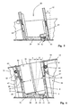
- Fig. 3 is a partial housing 30 of a portable, hand-held implement such as a hedge trimmer or motor chain saw shown.
- the sub-housing 30 has a rear Handle 43, which extends in the longitudinal direction of the housing part 30.
- a battery compartment 31 is formed, the recording of the battery pack 1 after Fig. 1 serves.
- the battery compartment 31 has in the direction of insertion 32 extending guide elements 33, which lie opposite each other on opposite broad sides 34.
- the guide elements 33 are in the illustrated embodiment designed as guide ribs 35, which are preferably formed integrally with the housing 30 and are located as elevations on the broad sides 34.
- the guide ribs 35 extend over a partial height R of the battery compartment 31, so do not extend beyond the overall height of the battery compartment 31.
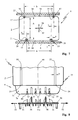
- each broad side 34 of the battery compartment 31 each have two guide ribs 35 parallel to each other, wherein the guide ribs 35 on the one broad side 34 a distance a and the guide ribs 35 on the opposite broad side 34 have a distance b to each other.
- the distance b is greater than the distance a, as well as the Fig. 7 can be removed.
- the guide elements 35 of a broad side 34 of the battery pack to the guide elements 35 on the other, opposite broad side 34 of the battery compartment have an offset v.
- the distance a of the guide portions 17 on the wide longitudinal side 8 of the battery pack 1 is less than the distance b of the guide portions 17 the wide longitudinal side 18.
- the distance a is within the distance b.
- the guide portions 17 on the broad sides 34 of the battery compartment 31 are arranged according to the offset v and the distances a and b.
- the width x of the guide groove 19 in the housing 2 of the battery pack is greater than the thickness (width) y a longitudinal rib 35 on a broadside 34 in the battery bay 31. Therefore, is - like Fig. 7 shows - the battery pack 1 with lateral clearance corresponding to the double arrow 36 in Fig. 7 led in the battery bay 31. Moreover, since the width B of the battery pack case 2 between the bottoms of the guide grooves 19 is smaller than the distance A of the opposing guide ribs 35 in the battery bay 31, the battery pack 1 is also held in the transverse direction in the direction of the double arrow 37 with little play.
- the guide ribs 35 enter the guide grooves 17 of the battery pack housing 2 via the open ends 24, wherein the battery pack 1 - in which by the position of the guide ribs 35 and guide grooves 19 structurally predetermined Drehlage - initially in the direction of the double arrows 36 and 37 with little play remains mobile. This facilitates the threading of the battery pack 1 in the battery compartment 31.
- the off-center guide grooves 29 in the narrow longitudinal sides 26 also ensure that the battery pack can be inserted into the battery compartment 31 only in a predetermined rotational position.
- the guide grooves 29 serve the correct position Positioning and mounting of the battery pack 1 in a charger, not shown.
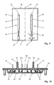
- the battery pack 1 is contacted at the connection head 4 with contact elements 51 of a contact plate 50, which are provided in the region of the bottom 38 of the battery compartment 31.
- a contact plate 50 is shown schematically.
- the contact plate 50 is - preferably threaded onto all guide elements 33 - threaded so that the contact plate 50 - can be lowered in accordance with the positioning of the battery pack 1 - in a structurally predetermined rotational position in the insertion direction 32 in the battery bay 31.
- the contact plate 50 on opposite longitudinal edges 52 recesses 53, wherein each recess 53 has a width K and a depth T.
- the width K of the recesses 53 is wider than the thickness (width) y of the guide ribs 35 in the battery compartment 31.
- the depth T of opposing recesses 53 is so dimensioned that the remaining contact plate portion between the recesses 53 has an extension P which is smaller than the distance A between the longitudinal edges of the guide ribs 19 ( Fig. 7 ).
- the lowered in the battery compartment 31 contact plate 50 is held in its plane with play on the guide ribs 35, resulting in a floating in the plane of the contact plate 50 storage of the contact plate 50 results.
- the contact plate 50 is movable in the plane of the plate due to the play of the guide ribs 35 in the recesses 53 in the direction of the double arrows 54 and 55.
- the contact plate 50 Due to the floating mounting of the contact plate 50 with the contacts 51 arranged thereon (FIG. Fig. 8 ) a positionally accurate threading of the contact elements 51 is ensured in the contact terminals 12.
- the contact plate 50 is held on a carrier insert 60, which is secured to the bottom 38 of the battery compartment 31.
- the carrier module 60 has a latching clip 61, the -.
- FIGS. 5 and 6 - Engages in a latching opening 39 in the bottom 38 of the battery pack 1.
- the latching opening 39 and the latching clip 61 are aligned with one another such that the floating mounting of the contact plate 50 is maintained at least in the direction of the double arrow 55, preferably also in the direction of the double arrow 54.
- the carrier drawer 60 can hold not only the contact plate 50, but also other components of the electrical appliance, for. B. electrical components 62 of the electrical device such as an on / off switch.
- the opposite broad sides 34 of the battery compartment 31 are - like the FIGS. 5 and 6 show - inclined at an angle ⁇ or ⁇ to the perpendicular 42 on the housing bottom 38 to the front or to the rear.
- the angle ⁇ or ⁇ is approximately between 2 ° and 20 °, so that a tilted position of the battery pack 1 in the battery compartment 31 results.
- the battery pack 1 is inclined by an angle ⁇ of 10 ° backwards. It may also be expedient to tilt the battery pack 1 forward by an angle ⁇ of, in particular, 15 °, as in FIG FIG. 6 is indicated.
- the carrier insert 60 also serves to fix the battery pack 1 in the in Fig. 6 shown insertion position.
- the carrier insert 60 has two to the broad sides 34 of the battery compartment 31 parallel edge walls 63, the distance E corresponds approximately to the thickness D of the battery pack 1.
- the thickness D of the battery pack is measured between its broad longitudinal sides 8 and 18. This will - like Fig. 6 shows - held in the insertion position of the battery pack 1 in the battery bay 31, the insertion end 25 in the carrier slot 60 approximately free of play, so that the battery pack 1 in the in Fig. 6 shown insertion position is fixed largely free of play.
- a clamping portion 40 has a structurally predetermined residual width y ', which corresponds approximately to the thickness (width) y of a guide rib 35. This ensures that during the insertion movement in the direction of insertion 32 of the battery pack 1 in the direction of the double arrow 36 (FIG. Fig. 7 ) shortly after reaching the guide ribs 35 without play on the guide ribs 35 is seated.
- the width y 'of the section 40 can also be formed slightly smaller than the thickness y of the guide rib 35, so that a clamping effect is achieved.
- insertion position of the battery pack 1 is fixed in the housing 30 without play.
- the upper housing part 27 forms, together with the lower housing part 28, the partial housing 30 of the implement.
- a battery pack 1 If a battery pack 1 is inserted into a battery compartment 31, it must be positioned in the correct rotational position and lowered in advance into the shaft 31 with its insertion end 25.
- the guide ribs 35 enter via the open ends 24 of the guide grooves 19 and provide a largely backlash-free aligned position of the battery pack 1 in the battery bay 31 when entering the clamping portions 40.
- the insertion end 25 moves into the carrier slot 60, whereby the battery pack 1 and thus the connection head 4 in the direction of the double arrow 37 (FIG. Fig. 7 ) is positioned.
- the connection head 4 approaches the contact plate 50 and the contact elements 51. Due to the floating bearing, the contact plate 50 is movable transversely to the insertion direction in the direction of the double arrow 55, so that an orientation of the contact plate 50 relative to the contact slots 10 of the connection head 4 on the battery pack 1 can be done.
- a centering slot 57 is assigned in the housing of the connection head 4.
- the centering slot 57 extends - similar to the contact slots 10 - from the bottom 7a of the connection head 4 in the end face 11.
- two Zentrierstege 56 are provided, between which the contact elements 51a are of control terminals, while the outer contact elements 51 are used for power transmission.
- the centering webs 56 which may also be designed as centering mandrel 58 or the like, project beyond the contact elements 51 and 51 a, so that first the centering webs 56 come into contact with the connection head 4.
- the centering slots 57 are slightly expanded, so that a slight threading of the centering heads 58 takes place in the centering slot 57 and an alignment of the contact plate 50 in the double arrow 55 relative to the connection head 4 is effected. This ensures that the contact elements 51 and 51a during further lowering of the battery pack 1 in the battery bay 31 are in the correct position to the contact slots 10 and can contact the contact terminals 12, 12a safely without mechanical damage.
- centering webs 56 project beyond the contact elements 51, 51a, these centering webs 56 also serve as protective elements against mechanical damage to the contact elements 12, 12a when the battery bay 31 is empty.
- the contact elements 51, 51a are inserted into the contact terminals 12, 12a in a plug-in / slide movement that consists of path components in the directions of the arrows 14 and 15 ( Fig. 2 ). As a result, a secure electrical contact is achieved.
- a cover 59 is placed on the side facing away from the terminal head 4 of the contact plate 50, whereby between the contact plate 50 and the cover 59 cable channels 49 can be formed for the guidance of connecting wires 16.
- a latching stop 69 which is formed at the end of a ramp 70 on a wide longitudinal side 8 of the battery pack housing 2.
- two locking ramps 70 are provided on a wide longitudinal side 8 between the guide grooves 19, the locking stops 69 are supported together on a latching pawl 64, which is formed correspondingly wide.
- detent stops 69 On the opposite wide longitudinal side 18 corresponding ramps 70 are provided with detent stops 69.
- the latching pawls 64 are pushed back when inserting the battery pack 1 in the battery compartment 31 until the detents 68 can engage behind the locking stops 69 and the spring 67, the latch 64 in the in Fig. 6 pivoting shown locking position.
- the pawls 64 are designed and stored so that the stored in the direction of arrow 41 spring force of the lifting spring 48 is introduced via the locking stops 69 in the latch 64 so that they perform a rotational movement in the direction of arrow 46, the detent pawls 64 thus in the rest position Apply force.
- This locking effect is achieved in that the force application point of the spring force of the lifting spring 48 at the detent end 68 at a distance w to the bearing pin 65 of the latch 64 and the detent end 68 is located between the battery pack 1 and the bearing pin 65.
- the two pawls 64 are opposite to the direction of arrow 46 to pivot, to which the battery pack 1 is slightly pressed by the user against the lifting spring 63 to produce sufficient clearance between the stop 69 and the locking end 68 to release the lock.
- the surfaces of the latching stop 69 on the battery pack 1 may be advantageous to design the surfaces of the latching stop 69 on the battery pack 1 in an inclined manner.
- the surface of the latching stopper 69 is at an angle ⁇ to the horizontal or to the housing bottom 6 of the battery pack housing 1 or to its end faces 7 and 20.
- Fig. 11 is schematically shown a further possibility of locking a battery pack 1 in a battery bay.
- the locking latch 71 shown there are displaceable transversely to the latching stops 69, wherein for releasing the battery pack, the user in the direction of arrow 46 must depress the locking latch 71 so that the locking legs 72 of the locking latch 71 release the locking stops 69.
- the locking latch 71 When inserting the battery pack, the locking latch 71 must also be actuated in the direction of arrow 46 to release the insertion direction of the battery pack 1.
Landscapes
- Engineering & Computer Science (AREA)
- Life Sciences & Earth Sciences (AREA)
- Chemical Kinetics & Catalysis (AREA)
- Chemical & Material Sciences (AREA)
- Electrochemistry (AREA)
- General Chemical & Material Sciences (AREA)
- Power Engineering (AREA)
- Biophysics (AREA)
- Computer Hardware Design (AREA)
- Biodiversity & Conservation Biology (AREA)
- Ecology (AREA)
- Forests & Forestry (AREA)
- Environmental Sciences (AREA)
- Mechanical Engineering (AREA)
- Battery Mounting, Suspending (AREA)
Applications Claiming Priority (1)
| Application Number | Priority Date | Filing Date | Title |
|---|---|---|---|
| DE102009012184A DE102009012184A1 (de) | 2009-02-27 | 2009-02-27 | Tragbares, handgeführtes Elektrogerät mit einem Akkupack |
Publications (3)
| Publication Number | Publication Date |
|---|---|
| EP2223779A2 true EP2223779A2 (fr) | 2010-09-01 |
| EP2223779A3 EP2223779A3 (fr) | 2012-06-27 |
| EP2223779B1 EP2223779B1 (fr) | 2016-01-27 |
Family
ID=42154678
Family Applications (1)
| Application Number | Title | Priority Date | Filing Date |
|---|---|---|---|
| EP10001083.4A Active EP2223779B1 (fr) | 2009-02-27 | 2010-02-03 | Appareil électrique portatif doté d'une batterie |
Country Status (4)
| Country | Link |
|---|---|
| US (1) | US8389143B2 (fr) |
| EP (1) | EP2223779B1 (fr) |
| CN (1) | CN101817178B (fr) |
| DE (1) | DE102009012184A1 (fr) |
Cited By (6)
| Publication number | Priority date | Publication date | Assignee | Title |
|---|---|---|---|---|
| WO2013186045A1 (fr) * | 2012-06-13 | 2013-12-19 | Hilti Aktiengesellschaft | Machine-outil à main |
| WO2013186047A1 (fr) * | 2012-06-13 | 2013-12-19 | Hilti Aktiengesellschaft | Machine-outil à main |
| EP3369530B1 (fr) | 2017-03-04 | 2021-09-01 | Andreas Stihl AG & Co. KG | Appareil de travail électrique à découplage de vibrations |
| US11440176B2 (en) | 2017-01-24 | 2022-09-13 | Techtronic Cordless Gp | Battery terminal holder for electric tools |
| EP4068484A1 (fr) * | 2021-03-30 | 2022-10-05 | Andreas Stihl AG & Co. KG | Appareil a accumulateur et système |
| EP4644049A1 (fr) * | 2024-04-30 | 2025-11-05 | Andreas Stihl AG & Co. KG | Appareil de travail doté d'un arbre et d'un bloc-batterie |
Families Citing this family (40)
| Publication number | Priority date | Publication date | Assignee | Title |
|---|---|---|---|---|
| DE102009012175A1 (de) * | 2009-02-27 | 2010-09-02 | Andreas Stihl Ag & Co. Kg | Elektroarbeitsgerät mit einem Akkupack |
| US8591242B2 (en) * | 2010-04-08 | 2013-11-26 | Illinois Tool Works Inc. | Floating battery contact module for a power tool |
| DE102010045993A1 (de) * | 2010-09-18 | 2012-03-22 | Andreas Stihl Ag & Co. Kg | Handgeführtes Arbeitsgerät mit einem elektrischen Antriebsmotor |
| JP5662105B2 (ja) | 2010-10-26 | 2015-01-28 | 株式会社マキタ | 二次電池パック |
| US9385403B2 (en) * | 2010-11-08 | 2016-07-05 | Raytheon Company | Battery pack |
| USD660788S1 (en) | 2011-03-04 | 2012-05-29 | Blount, Inc. | Battery |
| CN106181905A (zh) * | 2012-02-06 | 2016-12-07 | 苏州宝时得电动工具有限公司 | 手持电动工具 |
| CN103315682A (zh) * | 2013-06-26 | 2013-09-25 | 苏州金威特工具有限公司 | 一种设有电池槽的电动吸尘器 |
| AU2015354771B2 (en) | 2014-11-26 | 2018-07-26 | Techtronic Industries Co. Ltd. | Battery pack |
| CN209033767U (zh) | 2015-06-05 | 2019-06-28 | 米沃奇电动工具公司 | 可连接到电动工具并可由所述电动工具支撑的电池组 |
| EP3162513B1 (fr) * | 2015-10-30 | 2019-04-17 | Black & Decker Inc. | Moteur sans balai à puissance élevée |
| DE102015226448A1 (de) * | 2015-12-22 | 2017-06-22 | Robert Bosch Gmbh | Tragbare Werkzeugmaschine und Verfahren zur Herstellung einer tragbaren Werkzeugmaschine |
| DE102016003150A1 (de) * | 2016-03-16 | 2017-09-21 | Andreas Stihl Ag & Co. Kg | Handgeführtes Arbeitsgerät mit einem Elektromotor |
| US10158105B2 (en) | 2016-03-16 | 2018-12-18 | Tti (Macao Commercial Offshore) Limited | Battery pack latch mechanism |
| JP2018092746A (ja) * | 2016-11-30 | 2018-06-14 | 本田技研工業株式会社 | バッテリ取付構造 |
| EP3549432B1 (fr) * | 2016-11-30 | 2021-01-27 | Honda Motor Co., Ltd. | Machine de travail électrique |
| EP3392974A1 (fr) | 2017-04-21 | 2018-10-24 | HILTI Aktiengesellschaft | Batterie avec un ressort |
| AU2018307011B2 (en) * | 2017-07-27 | 2024-02-08 | Panasonic Energy Co., Ltd. | Battery pack and production method for same |
| EP3673532B1 (fr) * | 2017-09-27 | 2025-05-14 | Globe (Jiangsu) Co., Ltd. | Compartiment de batterie pour outils électriques |
| EP3701782B1 (fr) * | 2017-10-24 | 2025-06-25 | Suzhou Cleva Precision Machinery & Technology Co., Ltd. | Ensemble poignée et outil de jardinage le comprenant |
| CN109103374A (zh) * | 2018-08-01 | 2018-12-28 | 深圳市旭发智能科技有限公司 | 一种适用于无人机的电池 |
| CN108945489A (zh) * | 2018-08-01 | 2018-12-07 | 深圳市旭发智能科技有限公司 | 一种无人机电池的安装方法 |
| CN109148761A (zh) * | 2018-08-01 | 2019-01-04 | 深圳市旭发智能科技有限公司 | 一种无人机电池仓 |
| CN110085786B (zh) * | 2019-05-16 | 2021-10-08 | 涵速智能科技(上海)有限公司 | 一种水下电池密封舱 |
| WO2021107827A1 (fr) | 2019-11-25 | 2021-06-03 | Husqvarna Ab | Outil de travail portatif alimenté électriquement |
| CN113681518B (zh) * | 2020-05-18 | 2025-09-16 | 南京泉峰科技有限公司 | 电动工具 |
| USD1095405S1 (en) | 2020-07-15 | 2025-09-30 | Emerson Electric Co. | Battery pack |
| US11901527B2 (en) | 2020-07-15 | 2024-02-13 | Emerson Electric Co. | Battery packs for battery-powered appliances and connection system for same |
| USD1051036S1 (en) | 2020-07-15 | 2024-11-12 | Emerson Electric Co. | Battery pack |
| CN116250134A (zh) * | 2020-10-01 | 2023-06-09 | 胡斯华纳有限公司 | 用于动力工具的电池和模块化电池系统 |
| JP7340557B2 (ja) * | 2020-12-09 | 2023-09-07 | 深湾能源科技(舟山)有限公司 | ポータブル電源用の電池迅速交換装置 |
| EP4264733A1 (fr) * | 2020-12-15 | 2023-10-25 | Husqvarna Ab | Batteries résistant aux chocs et aux vibrations pour outils électriques |
| US12160127B2 (en) | 2021-12-09 | 2024-12-03 | Honda Motor Co., Ltd. | Battery terminal fixing apparatus and method for power equipment |
| DE102023201869A1 (de) | 2023-03-01 | 2024-09-05 | Robert Bosch Gesellschaft mit beschränkter Haftung | Betätigungseinheit zum Lösen und Festlegen von Energiespeichern |
| US12502719B2 (en) | 2023-06-09 | 2025-12-23 | Robert Bosch Tool Corporation | Cut-off saw |
| USD1087719S1 (en) | 2023-06-09 | 2025-08-12 | Robert Bosch Power Tools GmbH | Cutting tool |
| US12415223B2 (en) | 2023-06-09 | 2025-09-16 | Robert Bosch Power Tools GmbH | Cut-off saw |
| DE102023115798A1 (de) * | 2023-06-16 | 2024-12-19 | Andreas Stihl Ag & Co. Kg | Akkugerät, System und Verfahren |
| DE102023133076A1 (de) * | 2023-11-27 | 2025-05-28 | Andreas Stihl Ag & Co. Kg | Handführbares batteriebetreibbares Elektro-Bearbeitungsgerät und Bearbeitungssystem |
| DE102024114997A1 (de) * | 2024-05-28 | 2025-12-04 | Andreas Stihl Ag & Co. Kg | Handgeführtes Arbeitsgerät |
Citations (1)
| Publication number | Priority date | Publication date | Assignee | Title |
|---|---|---|---|---|
| DE19521426A1 (de) | 1995-06-14 | 1996-12-19 | Bosch Gmbh Robert | Handwerkzeugmaschine mit batteriegespeistem Antriebsmotor |
Family Cites Families (16)
| Publication number | Priority date | Publication date | Assignee | Title |
|---|---|---|---|---|
| US4871629A (en) * | 1988-02-04 | 1989-10-03 | Black & Decker Inc. | Latching arrangement for battery packs |
| JPH0829505B2 (ja) * | 1988-02-17 | 1996-03-27 | 株式会社マキタ | 携帯用の電池式電動工具 |
| DE3839840A1 (de) * | 1988-11-25 | 1990-05-31 | Proxxon Werkzeug Gmbh | Elektrisches handwerksgeraet |
| US5216371A (en) * | 1989-06-12 | 1993-06-01 | Ricoh Company, Ltd. | Battery pack including measuring and indicating |
| US5553675A (en) * | 1994-06-10 | 1996-09-10 | Minnesota Mining And Manufacturing Company | Orthopedic surgical device |
| US6319053B1 (en) * | 1998-11-13 | 2001-11-20 | Jonathan Neal Andrews | Battery vibration control apparatus |
| US6296065B1 (en) * | 1998-12-30 | 2001-10-02 | Black & Decker Inc. | Dual-mode non-isolated corded system for transportable cordless power tools |
| DE19911362A1 (de) | 1999-03-15 | 2000-09-21 | Hilti Ag | Batteriebetriebenes Bohrgerät |
| EP1036637A1 (fr) | 1999-03-17 | 2000-09-20 | De La Rue Giori S.A. | Appareil d'invalidation pour la perforation d'objets-plans |
| US6536536B1 (en) * | 1999-04-29 | 2003-03-25 | Stephen F. Gass | Power tools |
| GB2392002B (en) * | 2002-08-12 | 2004-10-13 | Choon Nang Elec Appl Mfy Ltd | Rechargeable battery pack |
| US7653963B2 (en) * | 2002-11-12 | 2010-02-02 | Black & Decker Inc. | AC/DC hand portable wet/dry vacuum having improved portability and convenience |
| CN1989675B (zh) * | 2004-05-24 | 2011-06-01 | 密尔沃基电动工具公司 | 用于给电池充电的方法和系统 |
| DE102005036448A1 (de) | 2005-08-03 | 2007-02-08 | Robert Bosch Gmbh | Elektrogerät, insbesondere Elektrohandwerkzeug |
| US7659694B2 (en) * | 2006-10-02 | 2010-02-09 | Snap-On Incorporated | Self-aligning terminal block for battery pack |
| DE102006050816B4 (de) * | 2006-10-27 | 2015-10-22 | Robert Bosch Gmbh | Elektrohandwerkzeugmaschine |
-
2009
- 2009-02-27 DE DE102009012184A patent/DE102009012184A1/de not_active Withdrawn
-
2010
- 2010-02-03 EP EP10001083.4A patent/EP2223779B1/fr active Active
- 2010-02-22 US US12/709,609 patent/US8389143B2/en active Active
- 2010-03-01 CN CN201010143648.6A patent/CN101817178B/zh active Active
Patent Citations (1)
| Publication number | Priority date | Publication date | Assignee | Title |
|---|---|---|---|---|
| DE19521426A1 (de) | 1995-06-14 | 1996-12-19 | Bosch Gmbh Robert | Handwerkzeugmaschine mit batteriegespeistem Antriebsmotor |
Cited By (8)
| Publication number | Priority date | Publication date | Assignee | Title |
|---|---|---|---|---|
| WO2013186045A1 (fr) * | 2012-06-13 | 2013-12-19 | Hilti Aktiengesellschaft | Machine-outil à main |
| WO2013186047A1 (fr) * | 2012-06-13 | 2013-12-19 | Hilti Aktiengesellschaft | Machine-outil à main |
| US9905966B2 (en) | 2012-06-13 | 2018-02-27 | Hilti Aktiengesellschaft | Hand-held machine tool |
| US11027406B2 (en) | 2012-06-13 | 2021-06-08 | Hilti Aktiengesellschaft | Hand machine tool |
| US11440176B2 (en) | 2017-01-24 | 2022-09-13 | Techtronic Cordless Gp | Battery terminal holder for electric tools |
| EP3369530B1 (fr) | 2017-03-04 | 2021-09-01 | Andreas Stihl AG & Co. KG | Appareil de travail électrique à découplage de vibrations |
| EP4068484A1 (fr) * | 2021-03-30 | 2022-10-05 | Andreas Stihl AG & Co. KG | Appareil a accumulateur et système |
| EP4644049A1 (fr) * | 2024-04-30 | 2025-11-05 | Andreas Stihl AG & Co. KG | Appareil de travail doté d'un arbre et d'un bloc-batterie |
Also Published As
| Publication number | Publication date |
|---|---|
| US8389143B2 (en) | 2013-03-05 |
| DE102009012184A1 (de) | 2010-09-02 |
| US20100221594A1 (en) | 2010-09-02 |
| CN101817178B (zh) | 2015-08-19 |
| EP2223779A3 (fr) | 2012-06-27 |
| EP2223779B1 (fr) | 2016-01-27 |
| CN101817178A (zh) | 2010-09-01 |
Similar Documents
| Publication | Publication Date | Title |
|---|---|---|
| EP2223779B1 (fr) | Appareil électrique portatif doté d'une batterie | |
| EP2224512B1 (fr) | Batterie pour un appareil de travail portatif | |
| EP2055967B1 (fr) | Bloc de batterie et appareil électrique | |
| DE112015003376B4 (de) | Elektrisch angetriebene Kettensäge | |
| DE2836907C2 (fr) | ||
| DE602004013398T2 (de) | batterieauswurfsmechanismus | |
| DE112013007758B3 (de) | Handgehaltene elektrische Schneidvorrichtung | |
| EP0374600B1 (fr) | Dispositif d'alimentation en courant | |
| EP3523838B1 (fr) | Dispositif d'accumulation d'énergie électrique et appareil électrique | |
| EP1517412B1 (fr) | Dispositif connecteur avec adaptateur | |
| DE102009012175A1 (de) | Elektroarbeitsgerät mit einem Akkupack | |
| EP3642892A1 (fr) | Dispositif interface de bloc-batterie | |
| DE202017006868U1 (de) | Batteriepack, Elektrogerät, das den Batteriepack verwendet, und Elektrogerätesystem | |
| EP2402123B1 (fr) | Machine-outil manuelle dotée d'un accumulateur d'énergie | |
| EP2007557B1 (fr) | Machine outil manuelle a accumulateur | |
| DE9313032U1 (de) | Mobiles Arbeitsgerät | |
| DE10040893A1 (de) | Struktur von elektrischen Anschlüssen zum Herstellen eines elektrischen Kontakts zwischen einem Batterieteil und einer elektrischen Vorrichtung | |
| EP1588541A1 (fr) | Prise multiple mobile comportant un plateau de support | |
| WO2007031143A1 (fr) | Batterie rechargeable | |
| DE202017006869U1 (de) | Batteriepack, Elektrogerät, das den Batteriepack verwendet, und Elektrogerätesystem | |
| DE102022103353A1 (de) | Batteriepack | |
| EP0673123B1 (fr) | Dispositif de suspension et maintien pour un appareil à main de radio communication portable | |
| DE102019218584A1 (de) | Akkubetriebenes Gerät mit einer Akkuschnittstelle | |
| DE102020201267A1 (de) | Akkuschnittstelle, Verbraucher mit einer Akkuschnittstelle und System aufweisend einen Verbraucher und einen Akkupack | |
| EP4068484A1 (fr) | Appareil a accumulateur et système |
Legal Events
| Date | Code | Title | Description |
|---|---|---|---|
| PUAI | Public reference made under article 153(3) epc to a published international application that has entered the european phase |
Free format text: ORIGINAL CODE: 0009012 |
|
| AK | Designated contracting states |
Kind code of ref document: A2 Designated state(s): AT BE BG CH CY CZ DE DK EE ES FI FR GB GR HR HU IE IS IT LI LT LU LV MC MK MT NL NO PL PT RO SE SI SK SM TR |
|
| AX | Request for extension of the european patent |
Extension state: AL BA RS |
|
| RIC1 | Information provided on ipc code assigned before grant |
Ipc: B25F 5/02 20060101AFI20111230BHEP Ipc: A01G 3/053 20060101ALI20111230BHEP Ipc: H02J 7/00 20060101ALI20111230BHEP |
|
| RIN1 | Information on inventor provided before grant (corrected) |
Inventor name: MUELLER, MATTHIAS Inventor name: ROSSKAMP, HEIKO, DR. Inventor name: MANG, HARALD Inventor name: REBER, VOLKER |
|
| PUAL | Search report despatched |
Free format text: ORIGINAL CODE: 0009013 |
|
| AK | Designated contracting states |
Kind code of ref document: A3 Designated state(s): AT BE BG CH CY CZ DE DK EE ES FI FR GB GR HR HU IE IS IT LI LT LU LV MC MK MT NL NO PL PT RO SE SI SK SM TR |
|
| AX | Request for extension of the european patent |
Extension state: AL BA RS |
|
| RIC1 | Information provided on ipc code assigned before grant |
Ipc: B25F 5/02 20060101AFI20120521BHEP Ipc: H02J 7/00 20060101ALI20120521BHEP Ipc: A01G 3/053 20060101ALI20120521BHEP |
|
| 17P | Request for examination filed |
Effective date: 20121220 |
|
| 17Q | First examination report despatched |
Effective date: 20130319 |
|
| REG | Reference to a national code |
Ref country code: DE Ref legal event code: R079 Ref document number: 502010010964 Country of ref document: DE Free format text: PREVIOUS MAIN CLASS: B25F0005020000 Ipc: H01M0002100000 |
|
| GRAP | Despatch of communication of intention to grant a patent |
Free format text: ORIGINAL CODE: EPIDOSNIGR1 |
|
| RIC1 | Information provided on ipc code assigned before grant |
Ipc: H02J 7/00 20060101ALI20150527BHEP Ipc: B25F 5/02 20060101ALI20150527BHEP Ipc: A01G 3/053 20060101ALI20150527BHEP Ipc: H01M 2/30 20060101ALI20150527BHEP Ipc: H01M 2/10 20060101AFI20150527BHEP |
|
| INTG | Intention to grant announced |
Effective date: 20150612 |
|
| GRAS | Grant fee paid |
Free format text: ORIGINAL CODE: EPIDOSNIGR3 |
|
| GRAA | (expected) grant |
Free format text: ORIGINAL CODE: 0009210 |
|
| AK | Designated contracting states |
Kind code of ref document: B1 Designated state(s): AT BE BG CH CY CZ DE DK EE ES FI FR GB GR HR HU IE IS IT LI LT LU LV MC MK MT NL NO PL PT RO SE SI SK SM TR |
|
| REG | Reference to a national code |
Ref country code: GB Ref legal event code: FG4D Free format text: NOT ENGLISH |
|
| REG | Reference to a national code |
Ref country code: CH Ref legal event code: EP |
|
| REG | Reference to a national code |
Ref country code: AT Ref legal event code: REF Ref document number: 773076 Country of ref document: AT Kind code of ref document: T Effective date: 20160215 |
|
| REG | Reference to a national code |
Ref country code: IE Ref legal event code: FG4D Free format text: LANGUAGE OF EP DOCUMENT: GERMAN |
|
| REG | Reference to a national code |
Ref country code: FR Ref legal event code: PLFP Year of fee payment: 7 |
|
| REG | Reference to a national code |
Ref country code: DE Ref legal event code: R096 Ref document number: 502010010964 Country of ref document: DE |
|
| REG | Reference to a national code |
Ref country code: LT Ref legal event code: MG4D |
|
| PG25 | Lapsed in a contracting state [announced via postgrant information from national office to epo] |
Ref country code: BE Free format text: LAPSE BECAUSE OF NON-PAYMENT OF DUE FEES Effective date: 20160229 |
|
| REG | Reference to a national code |
Ref country code: NL Ref legal event code: MP Effective date: 20160127 |
|
| PG25 | Lapsed in a contracting state [announced via postgrant information from national office to epo] |
Ref country code: NL Free format text: LAPSE BECAUSE OF FAILURE TO SUBMIT A TRANSLATION OF THE DESCRIPTION OR TO PAY THE FEE WITHIN THE PRESCRIBED TIME-LIMIT Effective date: 20160127 |
|
| PG25 | Lapsed in a contracting state [announced via postgrant information from national office to epo] |
Ref country code: GR Free format text: LAPSE BECAUSE OF FAILURE TO SUBMIT A TRANSLATION OF THE DESCRIPTION OR TO PAY THE FEE WITHIN THE PRESCRIBED TIME-LIMIT Effective date: 20160428 Ref country code: IT Free format text: LAPSE BECAUSE OF FAILURE TO SUBMIT A TRANSLATION OF THE DESCRIPTION OR TO PAY THE FEE WITHIN THE PRESCRIBED TIME-LIMIT Effective date: 20160127 Ref country code: FI Free format text: LAPSE BECAUSE OF FAILURE TO SUBMIT A TRANSLATION OF THE DESCRIPTION OR TO PAY THE FEE WITHIN THE PRESCRIBED TIME-LIMIT Effective date: 20160127 Ref country code: ES Free format text: LAPSE BECAUSE OF FAILURE TO SUBMIT A TRANSLATION OF THE DESCRIPTION OR TO PAY THE FEE WITHIN THE PRESCRIBED TIME-LIMIT Effective date: 20160127 Ref country code: HR Free format text: LAPSE BECAUSE OF FAILURE TO SUBMIT A TRANSLATION OF THE DESCRIPTION OR TO PAY THE FEE WITHIN THE PRESCRIBED TIME-LIMIT Effective date: 20160127 Ref country code: NO Free format text: LAPSE BECAUSE OF FAILURE TO SUBMIT A TRANSLATION OF THE DESCRIPTION OR TO PAY THE FEE WITHIN THE PRESCRIBED TIME-LIMIT Effective date: 20160427 |
|
| PG25 | Lapsed in a contracting state [announced via postgrant information from national office to epo] |
Ref country code: LV Free format text: LAPSE BECAUSE OF FAILURE TO SUBMIT A TRANSLATION OF THE DESCRIPTION OR TO PAY THE FEE WITHIN THE PRESCRIBED TIME-LIMIT Effective date: 20160127 Ref country code: LT Free format text: LAPSE BECAUSE OF FAILURE TO SUBMIT A TRANSLATION OF THE DESCRIPTION OR TO PAY THE FEE WITHIN THE PRESCRIBED TIME-LIMIT Effective date: 20160127 Ref country code: IS Free format text: LAPSE BECAUSE OF FAILURE TO SUBMIT A TRANSLATION OF THE DESCRIPTION OR TO PAY THE FEE WITHIN THE PRESCRIBED TIME-LIMIT Effective date: 20160527 Ref country code: PL Free format text: LAPSE BECAUSE OF FAILURE TO SUBMIT A TRANSLATION OF THE DESCRIPTION OR TO PAY THE FEE WITHIN THE PRESCRIBED TIME-LIMIT Effective date: 20160127 Ref country code: SE Free format text: LAPSE BECAUSE OF FAILURE TO SUBMIT A TRANSLATION OF THE DESCRIPTION OR TO PAY THE FEE WITHIN THE PRESCRIBED TIME-LIMIT Effective date: 20160127 Ref country code: PT Free format text: LAPSE BECAUSE OF FAILURE TO SUBMIT A TRANSLATION OF THE DESCRIPTION OR TO PAY THE FEE WITHIN THE PRESCRIBED TIME-LIMIT Effective date: 20160527 |
|
| REG | Reference to a national code |
Ref country code: CH Ref legal event code: PL |
|
| REG | Reference to a national code |
Ref country code: DE Ref legal event code: R097 Ref document number: 502010010964 Country of ref document: DE |
|
| PG25 | Lapsed in a contracting state [announced via postgrant information from national office to epo] |
Ref country code: LI Free format text: LAPSE BECAUSE OF NON-PAYMENT OF DUE FEES Effective date: 20160229 Ref country code: EE Free format text: LAPSE BECAUSE OF FAILURE TO SUBMIT A TRANSLATION OF THE DESCRIPTION OR TO PAY THE FEE WITHIN THE PRESCRIBED TIME-LIMIT Effective date: 20160127 Ref country code: MC Free format text: LAPSE BECAUSE OF FAILURE TO SUBMIT A TRANSLATION OF THE DESCRIPTION OR TO PAY THE FEE WITHIN THE PRESCRIBED TIME-LIMIT Effective date: 20160127 Ref country code: CH Free format text: LAPSE BECAUSE OF NON-PAYMENT OF DUE FEES Effective date: 20160229 Ref country code: DK Free format text: LAPSE BECAUSE OF FAILURE TO SUBMIT A TRANSLATION OF THE DESCRIPTION OR TO PAY THE FEE WITHIN THE PRESCRIBED TIME-LIMIT Effective date: 20160127 |
|
| PG25 | Lapsed in a contracting state [announced via postgrant information from national office to epo] |
Ref country code: SM Free format text: LAPSE BECAUSE OF FAILURE TO SUBMIT A TRANSLATION OF THE DESCRIPTION OR TO PAY THE FEE WITHIN THE PRESCRIBED TIME-LIMIT Effective date: 20160127 Ref country code: SK Free format text: LAPSE BECAUSE OF FAILURE TO SUBMIT A TRANSLATION OF THE DESCRIPTION OR TO PAY THE FEE WITHIN THE PRESCRIBED TIME-LIMIT Effective date: 20160127 Ref country code: CZ Free format text: LAPSE BECAUSE OF FAILURE TO SUBMIT A TRANSLATION OF THE DESCRIPTION OR TO PAY THE FEE WITHIN THE PRESCRIBED TIME-LIMIT Effective date: 20160127 Ref country code: RO Free format text: LAPSE BECAUSE OF FAILURE TO SUBMIT A TRANSLATION OF THE DESCRIPTION OR TO PAY THE FEE WITHIN THE PRESCRIBED TIME-LIMIT Effective date: 20160127 |
|
| REG | Reference to a national code |
Ref country code: IE Ref legal event code: MM4A |
|
| PLBE | No opposition filed within time limit |
Free format text: ORIGINAL CODE: 0009261 |
|
| STAA | Information on the status of an ep patent application or granted ep patent |
Free format text: STATUS: NO OPPOSITION FILED WITHIN TIME LIMIT |
|
| 26N | No opposition filed |
Effective date: 20161028 |
|
| PG25 | Lapsed in a contracting state [announced via postgrant information from national office to epo] |
Ref country code: IE Free format text: LAPSE BECAUSE OF NON-PAYMENT OF DUE FEES Effective date: 20160203 |
|
| REG | Reference to a national code |
Ref country code: FR Ref legal event code: PLFP Year of fee payment: 8 |
|
| PG25 | Lapsed in a contracting state [announced via postgrant information from national office to epo] |
Ref country code: BG Free format text: LAPSE BECAUSE OF FAILURE TO SUBMIT A TRANSLATION OF THE DESCRIPTION OR TO PAY THE FEE WITHIN THE PRESCRIBED TIME-LIMIT Effective date: 20160427 Ref country code: SI Free format text: LAPSE BECAUSE OF FAILURE TO SUBMIT A TRANSLATION OF THE DESCRIPTION OR TO PAY THE FEE WITHIN THE PRESCRIBED TIME-LIMIT Effective date: 20160127 |
|
| REG | Reference to a national code |
Ref country code: AT Ref legal event code: MM01 Ref document number: 773076 Country of ref document: AT Kind code of ref document: T Effective date: 20160203 |
|
| PG25 | Lapsed in a contracting state [announced via postgrant information from national office to epo] |
Ref country code: AT Free format text: LAPSE BECAUSE OF NON-PAYMENT OF DUE FEES Effective date: 20160203 |
|
| PG25 | Lapsed in a contracting state [announced via postgrant information from national office to epo] |
Ref country code: MT Free format text: LAPSE BECAUSE OF FAILURE TO SUBMIT A TRANSLATION OF THE DESCRIPTION OR TO PAY THE FEE WITHIN THE PRESCRIBED TIME-LIMIT Effective date: 20160127 |
|
| REG | Reference to a national code |
Ref country code: FR Ref legal event code: PLFP Year of fee payment: 9 |
|
| PG25 | Lapsed in a contracting state [announced via postgrant information from national office to epo] |
Ref country code: HU Free format text: LAPSE BECAUSE OF FAILURE TO SUBMIT A TRANSLATION OF THE DESCRIPTION OR TO PAY THE FEE WITHIN THE PRESCRIBED TIME-LIMIT; INVALID AB INITIO Effective date: 20100203 Ref country code: CY Free format text: LAPSE BECAUSE OF FAILURE TO SUBMIT A TRANSLATION OF THE DESCRIPTION OR TO PAY THE FEE WITHIN THE PRESCRIBED TIME-LIMIT Effective date: 20160127 |
|
| PG25 | Lapsed in a contracting state [announced via postgrant information from national office to epo] |
Ref country code: LU Free format text: LAPSE BECAUSE OF NON-PAYMENT OF DUE FEES Effective date: 20160203 Ref country code: MK Free format text: LAPSE BECAUSE OF FAILURE TO SUBMIT A TRANSLATION OF THE DESCRIPTION OR TO PAY THE FEE WITHIN THE PRESCRIBED TIME-LIMIT Effective date: 20160127 Ref country code: TR Free format text: LAPSE BECAUSE OF FAILURE TO SUBMIT A TRANSLATION OF THE DESCRIPTION OR TO PAY THE FEE WITHIN THE PRESCRIBED TIME-LIMIT Effective date: 20160127 |
|
| REG | Reference to a national code |
Ref country code: DE Ref legal event code: R079 Ref document number: 502010010964 Country of ref document: DE Free format text: PREVIOUS MAIN CLASS: H01M0002100000 Ipc: H01M0050200000 |
|
| PGFP | Annual fee paid to national office [announced via postgrant information from national office to epo] |
Ref country code: FR Payment date: 20230223 Year of fee payment: 14 |
|
| PGFP | Annual fee paid to national office [announced via postgrant information from national office to epo] |
Ref country code: GB Payment date: 20230214 Year of fee payment: 14 |
|
| GBPC | Gb: european patent ceased through non-payment of renewal fee |
Effective date: 20240203 |
|
| PG25 | Lapsed in a contracting state [announced via postgrant information from national office to epo] |
Ref country code: GB Free format text: LAPSE BECAUSE OF NON-PAYMENT OF DUE FEES Effective date: 20240203 |
|
| PG25 | Lapsed in a contracting state [announced via postgrant information from national office to epo] |
Ref country code: FR Free format text: LAPSE BECAUSE OF NON-PAYMENT OF DUE FEES Effective date: 20240229 |
|
| PG25 | Lapsed in a contracting state [announced via postgrant information from national office to epo] |
Ref country code: GB Free format text: LAPSE BECAUSE OF NON-PAYMENT OF DUE FEES Effective date: 20240203 Ref country code: FR Free format text: LAPSE BECAUSE OF NON-PAYMENT OF DUE FEES Effective date: 20240229 |
|
| PGFP | Annual fee paid to national office [announced via postgrant information from national office to epo] |
Ref country code: DE Payment date: 20260220 Year of fee payment: 17 |