EP2224128A2 - Eolienne avec un système de freinage - Google Patents
Eolienne avec un système de freinage Download PDFInfo
- Publication number
- EP2224128A2 EP2224128A2 EP10001980A EP10001980A EP2224128A2 EP 2224128 A2 EP2224128 A2 EP 2224128A2 EP 10001980 A EP10001980 A EP 10001980A EP 10001980 A EP10001980 A EP 10001980A EP 2224128 A2 EP2224128 A2 EP 2224128A2
- Authority
- EP
- European Patent Office
- Prior art keywords
- shaft
- rotor
- brake
- wind turbine
- caliper
- Prior art date
- Legal status (The legal status is an assumption and is not a legal conclusion. Google has not performed a legal analysis and makes no representation as to the accuracy of the status listed.)
- Withdrawn
Links
- 230000002040 relaxant effect Effects 0.000 claims abstract 3
- 239000012530 fluid Substances 0.000 claims description 5
- 230000006835 compression Effects 0.000 claims description 3
- 238000007906 compression Methods 0.000 claims description 3
- 125000006850 spacer group Chemical group 0.000 claims description 3
- 238000007789 sealing Methods 0.000 claims description 2
- 239000002184 metal Substances 0.000 claims 2
- 230000000712 assembly Effects 0.000 claims 1
- 238000000429 assembly Methods 0.000 claims 1
- 238000012544 monitoring process Methods 0.000 claims 1
- 230000001960 triggered effect Effects 0.000 claims 1
- 230000005540 biological transmission Effects 0.000 description 4
- 230000033001 locomotion Effects 0.000 description 3
- 229910000831 Steel Inorganic materials 0.000 description 2
- 238000012423 maintenance Methods 0.000 description 2
- 239000010959 steel Substances 0.000 description 2
- 230000007797 corrosion Effects 0.000 description 1
- 238000005260 corrosion Methods 0.000 description 1
- 230000001419 dependent effect Effects 0.000 description 1
- 238000011161 development Methods 0.000 description 1
- 230000018109 developmental process Effects 0.000 description 1
- 230000007257 malfunction Effects 0.000 description 1
- 238000005096 rolling process Methods 0.000 description 1
Images

Classifications
-
- F—MECHANICAL ENGINEERING; LIGHTING; HEATING; WEAPONS; BLASTING
- F03—MACHINES OR ENGINES FOR LIQUIDS; WIND, SPRING, OR WEIGHT MOTORS; PRODUCING MECHANICAL POWER OR A REACTIVE PROPULSIVE THRUST, NOT OTHERWISE PROVIDED FOR
- F03D—WIND MOTORS
- F03D7/00—Controlling wind motors
- F03D7/02—Controlling wind motors the wind motors having rotation axis substantially parallel to the air flow entering the rotor
- F03D7/0264—Controlling wind motors the wind motors having rotation axis substantially parallel to the air flow entering the rotor for stopping; controlling in emergency situations
- F03D7/0268—Parking or storm protection
-
- F—MECHANICAL ENGINEERING; LIGHTING; HEATING; WEAPONS; BLASTING
- F03—MACHINES OR ENGINES FOR LIQUIDS; WIND, SPRING, OR WEIGHT MOTORS; PRODUCING MECHANICAL POWER OR A REACTIVE PROPULSIVE THRUST, NOT OTHERWISE PROVIDED FOR
- F03D—WIND MOTORS
- F03D7/00—Controlling wind motors
- F03D7/02—Controlling wind motors the wind motors having rotation axis substantially parallel to the air flow entering the rotor
- F03D7/0244—Controlling wind motors the wind motors having rotation axis substantially parallel to the air flow entering the rotor for braking
- F03D7/0248—Controlling wind motors the wind motors having rotation axis substantially parallel to the air flow entering the rotor for braking by mechanical means acting on the power train
-
- F—MECHANICAL ENGINEERING; LIGHTING; HEATING; WEAPONS; BLASTING
- F05—INDEXING SCHEMES RELATING TO ENGINES OR PUMPS IN VARIOUS SUBCLASSES OF CLASSES F01-F04
- F05B—INDEXING SCHEME RELATING TO WIND, SPRING, WEIGHT, INERTIA OR LIKE MOTORS, TO MACHINES OR ENGINES FOR LIQUIDS COVERED BY SUBCLASSES F03B, F03D AND F03G
- F05B2260/00—Function
- F05B2260/90—Braking
- F05B2260/902—Braking using frictional mechanical forces
-
- F—MECHANICAL ENGINEERING; LIGHTING; HEATING; WEAPONS; BLASTING
- F05—INDEXING SCHEMES RELATING TO ENGINES OR PUMPS IN VARIOUS SUBCLASSES OF CLASSES F01-F04
- F05B—INDEXING SCHEME RELATING TO WIND, SPRING, WEIGHT, INERTIA OR LIKE MOTORS, TO MACHINES OR ENGINES FOR LIQUIDS COVERED BY SUBCLASSES F03B, F03D AND F03G
- F05B2270/00—Control
- F05B2270/60—Control system actuates through
- F05B2270/604—Control system actuates through hydraulic actuators
-
- Y—GENERAL TAGGING OF NEW TECHNOLOGICAL DEVELOPMENTS; GENERAL TAGGING OF CROSS-SECTIONAL TECHNOLOGIES SPANNING OVER SEVERAL SECTIONS OF THE IPC; TECHNICAL SUBJECTS COVERED BY FORMER USPC CROSS-REFERENCE ART COLLECTIONS [XRACs] AND DIGESTS
- Y02—TECHNOLOGIES OR APPLICATIONS FOR MITIGATION OR ADAPTATION AGAINST CLIMATE CHANGE
- Y02E—REDUCTION OF GREENHOUSE GAS [GHG] EMISSIONS, RELATED TO ENERGY GENERATION, TRANSMISSION OR DISTRIBUTION
- Y02E10/00—Energy generation through renewable energy sources
- Y02E10/70—Wind energy
- Y02E10/72—Wind turbines with rotation axis in wind direction
Definitions
- the invention relates to a wind turbine with a brake system according to the preamble of claim 1.
- wind turbines can be automatically stopped at high wind speeds and in case of malfunction of important components. Even if, for example, the generator is overheated or disconnected from the electrical network, the rotor is no longer sufficiently loaded and braked in its rotary motion. He will then accelerate and exceed the allowable speed. In these situations, it is important to have reliable speed overshoot protection.
- the main brake system in modern wind turbines, especially larger design, is the aerodynamic braking system.
- the stall is used at high wind speeds and / or adjusting the rotor blade pitch to avoid overspeed of the rotor.
- a mechanical brake system is additionally used and serves as an emergency system and as a parking brake. It is activated during safety and emergency shutdowns, manual stop, maintenance and repair in the nacelle.
- a mechanical brake system can also be used for speed overshoot protection, especially for systems of smaller size, which usually have no (motor) adjustment of the rotor blade angle of attack.
- the object of the present invention is to provide a wind turbine with a suitable in particular for plants of smaller size without rotor blade adjustment suitable braking system, which easily, compact, inexpensive to produce and easy to assemble, and stops the rotor automatically in case of excessive wind or damage reliably and safely.
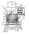
- the drawing shows schematically a part of a wind turbine 1 with a tubular, preferably z. B. for maintenance tiltable trained mast 2, of which only the upper part is shown.
- a nacelle machine head, not explicitly shown
- a pivot bearing 3 is pivotally mounted on the mast 2 .
- a rotor 4 with rotor bearing 16, with rotor flange 5, with horizontal rotor shaft 6, with hub 7 and rotor blades.
- the rotor shaft 6 is eg via a gear 10 with a horizontal shaft 12 for driving a rotatably mounted in the nacelle consumer 14, for example.
- the transmission is at a downforce (vertical shaft) preferably a bevel gear and at a drive to the rear (horizontal shaft) a planetary gear, possibly a spur gear, a generator then behind the gear, is arranged coaxially in a planetary gear.
- the generator can also be driven directly by the rotor become.
- compressors of a heat pump can be driven, with additional use an additional output shaft is provided, for example, in the form of a transmission with double shaft output.
- the rotor 4 is rotatably mounted in a rotor bearing 16, which usually consists of one or more rolling bearings and one or more bearing housings.
- the wind turbine 1 is equipped with a brake system 18, which has a mounted on the rotor shaft 6 and / or the vertical and / or horizontal shaft 15, 12 brake disc 20 and a first transverse to the brake disc 20 movable assembly having a brake disc cross-housing , the so-called caliper 22 has.
- Both sides of the brake disc 20 are transverse to the brake disc movable brake pads 24, 26 z. B. on Bremsbelagsträgem (not shown).
- On one side of the brake disc (20) is a pneumatically or hydraulically actuated, transversely to the brake disc 20 movable second assembly 28, hereinafter referred to as pushing means.
- pushing means On one side of the brake disc (20) is a pneumatically or hydraulically actuated, transversely to the brake disc 20 movable second assembly 28, hereinafter referred to as pushing means.
- the brake pads (24, 26) to the brake disc 20 pressed by a clamping means 30 with a clamping force.
- a pneumatic or hydraulic actuator 32 is provided, which builds up a force acting against the clamping force upon application of pressure.
- the caliper 22 and the thrust means 28 are positively connected to support the braking torque in the circumferential direction with the rotor bearing 16 or other supporting components in the nacelle, with an axially to the brake disc 20 executable mobility of the two components to compensate for the control movements and Bremsenverschl dealtes example is ensured in a groove or a slot or along a toothing.
- the actuator 32 is supported between a part of the brake caliper 22 which is remote from the rotor and is acted upon by the tensioning means 30 and at least part of the pushing means 28.
- the caliper 22 is preferably formed by two annular, axially spaced, the corresponding shaft enclosing, preferably made by means of a laser cut sheet steel, plate-shaped structural elements 38, 40 are formed, which are connected to each other at the outer periphery by connecting means such as screws, spacers or sheets.
- the thrust means 28 has the function to receive the actuator 32 and to direct its force in the caliper 22 and the clamping means 30. It preferably consists of two annular or plate-shaped, axially spaced structural elements 42, 44 of e.g. laser-cut sheet steel, of which a structural element 44 is disposed within the caliper 22.
- the two annular structural elements 42, 44 of the pusher 28 are connected to each other by suitable, through corresponding recesses in the structural element 34 of the caliper 22 guided through connecting means such as screws, spacers or sheets.
- the tensioning means 30 is preferably arranged within the caliper 22 and is supported thereby between the structural element 38 of the caliper 22 and the structural element 44 of the pushing means 28.
- the actuator 32 is preferably disposed within the pusher 28 and is supported between a structural member 38 of the caliper 22 and a structural member 42 of the pusher means 28.
- the above-mentioned positive connection 29 is formed between the structural elements 38, 42, 44, and the rotor bearing 16 or other supporting parts.
- the biasing means 30 or 30 are formed by a spring assembly, which consists of individual, annularly around the rotor bearing 16 arranged around helical compression springs or from a wound around the rotor bearing 16 around helical compression spring or from a rotor bearing 16 around the plate spring.
- the actuator 32 consists of a, by means of a pressurized fluid, preferably air, operable element according to the invention ring around the rotor bearing 16 and the corresponding shaft 6, 12, 15, where the brake system 18 is effective.
- a pressurized fluid preferably air
- the actuator 32 is preferably designed as an elastic, stretchable, around the rotor bearing 16 around in the annular space 50 arranged member 51, which is preferably formed by a hose or a tire with hose or a tubeless, itself on a corresponding rim self-sealing tire, in the pneumatic or hydraulic pressure medium can be fed.
- the hose When the actuator 32 is acted upon by the pressure medium, the hose expands elastically by exerting a preferably axially acting spreading force on the structural element 42, whereby the caliper 22 and the pusher 28 are displaced relative to each other by compressing the tensioning means 30 and the brake pads 24, 26 are released from the rotor 4 decelerating position on the brake disc 20.
- the preferred tube is permanently tight executable and fits ideally in the annular space 50 around the rotor bearing 16 around a. Especially in the axial direction, it can build up large forces for the relaxation of the highly effective clamping means 30 even at low pneumatic pressure, since it fills the available annular cross-section around the shaft to be braked over a large area.
- the preferred compressed air is reliable, easy and cheap available and easy to lead to the brake system 18; thus predestined for use on smaller wind turbines.
- the pressure medium is preferably fed via hoses or lines 60 and a rotary feedthrough 62 according to the invention with rotary seals 64 through the pivot bearing 3 in the nacelle and in the actuator 32.
- the pressure medium feed into the actuator 32 by means of a be activated by centrifugal weights of a rotatable shaft valve or via a centrifugal force actuated switch of an electrically controlled valve.
- an automatic overspeed protection function is achieved, which operates independently of the operation of a controller provided for controlling the brake system 18.
- the actuator 32 or the entire brake system 18 can also on the opposite side of the rotor 4 Be positioned gear / generator assembly 10, 14. It can then be annular or cylindrical.
- the structural elements 40 and 44 of the caliper 22 and the pusher 28 may be formed directly as a brake pad carrier, wherein the brake pads 24, 26 may be adhered to the surfaces.
- the brake pads 24, 26 are connected to their own brake pad struts, so that a form-fitting or screwable attachable brake pad is formed, which is replaceable in the event of wear.
- Imbalanced icing of the rotor 4 or damage to the rotor blades 8 can lead to an untypical vibration load of the wind turbine.
- an imbalance sensor is provided which activates the braking system 18 by means of the control device or by means of a valve.
- a drum brake with drum mounted on the rotor shaft 4 and / or the horizontal and / or vertical shaft 12, 15 can also be provided.
- an in-drum tensioning means is provided, e.g. by applying an axial or radially inward or outward positioning movement of an elastic actuator, the required actuating forces.
- the nacelle of the wind turbine is by the inventive compact brake system 18 with the inner rotor bearing 16 and a directly driven generator 14 or a planetary gear plus. Generator or an angle gear to a compact, reliable, because safely brakable, integral unit.
Landscapes
- Engineering & Computer Science (AREA)
- Life Sciences & Earth Sciences (AREA)
- Sustainable Development (AREA)
- Sustainable Energy (AREA)
- Chemical & Material Sciences (AREA)
- Combustion & Propulsion (AREA)
- Mechanical Engineering (AREA)
- General Engineering & Computer Science (AREA)
- Braking Arrangements (AREA)
- Wind Motors (AREA)
Applications Claiming Priority (1)
| Application Number | Priority Date | Filing Date | Title |
|---|---|---|---|
| DE102009010671A DE102009010671A1 (de) | 2009-02-27 | 2009-02-27 | Windkraftanlage mit einem Bremssystem |
Publications (2)
| Publication Number | Publication Date |
|---|---|
| EP2224128A2 true EP2224128A2 (fr) | 2010-09-01 |
| EP2224128A3 EP2224128A3 (fr) | 2014-04-09 |
Family
ID=41800810
Family Applications (1)
| Application Number | Title | Priority Date | Filing Date |
|---|---|---|---|
| EP10001980.1A Withdrawn EP2224128A3 (fr) | 2009-02-27 | 2010-02-26 | Eolienne avec un système de freinage |
Country Status (2)
| Country | Link |
|---|---|
| EP (1) | EP2224128A3 (fr) |
| DE (1) | DE102009010671A1 (fr) |
Cited By (3)
| Publication number | Priority date | Publication date | Assignee | Title |
|---|---|---|---|---|
| CN103306908A (zh) * | 2013-06-26 | 2013-09-18 | 江苏大学 | 一种风能垂直传动系统保护装置 |
| WO2015082114A1 (fr) * | 2013-12-06 | 2015-06-11 | Siemens Aktiengesellschaft | Dispositif de freinage d'une éolienne |
| CN116696666A (zh) * | 2023-06-27 | 2023-09-05 | 河南华殊电力工程有限公司 | 一种风力发电机过热紧急制动装置 |
Families Citing this family (2)
| Publication number | Priority date | Publication date | Assignee | Title |
|---|---|---|---|---|
| DE102017203497A1 (de) | 2017-03-03 | 2018-09-06 | Aktiebolaget Skf | Bremse einer Großwindkraftanlage |
| DE102017006103A1 (de) | 2017-06-28 | 2019-01-03 | Hartwig Schwieger | Elektrisches und pneumatisches Steuerungssystem |
Family Cites Families (9)
| Publication number | Priority date | Publication date | Assignee | Title |
|---|---|---|---|---|
| DE2514085A1 (de) * | 1975-03-29 | 1976-10-07 | Klaue Hermann | Vollscheibenbremse mit automatischer lueftspiel-einstellung, insbesondere fuer kraftfahrzeuge |
| US4146116A (en) * | 1977-09-15 | 1979-03-27 | Rockwell International Corporation | Friction brake |
| FR2407845A1 (fr) * | 1977-11-07 | 1979-06-01 | Rech Transmissions Spe Et | Dispositif pour le freinage d'une roue de vehicule |
| US5178518A (en) * | 1990-05-14 | 1993-01-12 | Carter Sr J Warne | Free-yaw, free-pitch wind-driven electric generator apparatus |
| SE507495C2 (sv) * | 1996-10-10 | 1998-06-15 | Volvo Wheel Loaders Ab | Speljustering |
| FR2810374B1 (fr) * | 2000-06-19 | 2004-09-03 | Jeumont Ind | Dispositif de production de courant electrique a partir d'energie eolienne |
| DE10320580A1 (de) * | 2003-05-07 | 2004-11-25 | Bosch Rexroth Ag | Bremseinrichtung für eine Windenergieanlage mit einem die Windenergie in eine Drehbewegung umsetzenden Rotor und Verfahren zum Betrieb einer derartigen Bremseinrichtung |
| DK2041430T3 (da) * | 2006-07-17 | 2012-01-16 | S B Patent Holdings Aps | Bremseindretning |
| US8028604B2 (en) * | 2007-01-26 | 2011-10-04 | General Electric Company | Methods and systems for turning rotary components within rotary machines |
-
2009
- 2009-02-27 DE DE102009010671A patent/DE102009010671A1/de not_active Withdrawn
-
2010
- 2010-02-26 EP EP10001980.1A patent/EP2224128A3/fr not_active Withdrawn
Non-Patent Citations (1)
| Title |
|---|
| None |
Cited By (5)
| Publication number | Priority date | Publication date | Assignee | Title |
|---|---|---|---|---|
| CN103306908A (zh) * | 2013-06-26 | 2013-09-18 | 江苏大学 | 一种风能垂直传动系统保护装置 |
| CN103306908B (zh) * | 2013-06-26 | 2015-03-04 | 江苏大学 | 一种风能垂直传动系统保护装置 |
| WO2015082114A1 (fr) * | 2013-12-06 | 2015-06-11 | Siemens Aktiengesellschaft | Dispositif de freinage d'une éolienne |
| CN116696666A (zh) * | 2023-06-27 | 2023-09-05 | 河南华殊电力工程有限公司 | 一种风力发电机过热紧急制动装置 |
| CN116696666B (zh) * | 2023-06-27 | 2024-01-23 | 河南华殊电力工程有限公司 | 一种风力发电机过热紧急制动装置 |
Also Published As
| Publication number | Publication date |
|---|---|
| EP2224128A3 (fr) | 2014-04-09 |
| DE102009010671A1 (de) | 2010-09-30 |
Similar Documents
| Publication | Publication Date | Title |
|---|---|---|
| EP2602482B1 (fr) | Eolienne | |
| EP2116722B1 (fr) | Positionnement du rotor d'une éolienne | |
| EP2829365B1 (fr) | Procédé et dispositif destinés au freinage d'un système d'axe de robot | |
| DE4221783C2 (de) | Vorrichtung zur Verstellung von Rotorblättern | |
| EP3800345A1 (fr) | Unité de réglage et/ou d'entraînement, éolienne doté d'une telle unité de réglage et/ou d'entraînement et procédé de commande d'une telle unité de réglage et/ou d'entraînement | |
| EP2224128A2 (fr) | Eolienne avec un système de freinage | |
| WO1999023384A1 (fr) | Entrainement pour pales de rotor d'installations eoliennes | |
| EP1483515A1 (fr) | Frein, en particulier pour aerogenerateur | |
| EP3597903B1 (fr) | Système de lacet pour éolienne | |
| DE102012101484A1 (de) | Verfahren und Einrichtung zur Abbremsung einer Windenergieanlage in einem Notfall | |
| EP2479428A1 (fr) | Eolienne avec un dispositif de freinage et procédé de freinage ainsi que l'utilisation du dispositif de freinage | |
| CH703047A2 (de) | Hybridwirkzylinder. | |
| WO2017050962A1 (fr) | Entraînement de grue motorisé | |
| EP2389509B1 (fr) | Installation de production d'energie stationnaire dotee d'un dispositif de freinage | |
| WO2017198384A2 (fr) | Système de freinage ainsi que dispositif de précontrainte pour ledit système de freinage | |
| DE102008036072B4 (de) | Bremsvorrichtung | |
| EP2602481B1 (fr) | Assemblage pour la fixation de l'angle d'une pale de rotor d'une éolienne | |
| WO2003040556A1 (fr) | Procede et dispositif de deceleration d'un rotor d'un convertisseur d'energie eolienne | |
| DE102004027992B4 (de) | Windenergieanlage mit einem Azimutsystem | |
| EP3580450B1 (fr) | Éolienne comprenant des turbines radiales et un générateur | |
| DE102009032873A1 (de) | Bremseinrichtung für Windenergieanlage | |
| EP2698533A1 (fr) | Pas variable électro-hydraulique, éolienne ou centrale hydraulique et procédé de fonctionnement d'un pas variable électro-hydraulique | |
| EP4352377A1 (fr) | Ressort élastomère et entraînement azimutal doté d'un ressort élastomère | |
| EP1866543B1 (fr) | Procédé et dispositif permettant de faire freiner le rotor d'une éolienne | |
| WO2011107208A2 (fr) | Procédé pour freiner une éolienne et dispositif de freinage permettant de mettre en oeuvre ce procédé |
Legal Events
| Date | Code | Title | Description |
|---|---|---|---|
| PUAI | Public reference made under article 153(3) epc to a published international application that has entered the european phase |
Free format text: ORIGINAL CODE: 0009012 |
|
| AK | Designated contracting states |
Kind code of ref document: A2 Designated state(s): AT BE BG CH CY CZ DE DK EE ES FI FR GB GR HR HU IE IS IT LI LT LU LV MC MK MT NL NO PL PT RO SE SI SK SM TR |
|
| AX | Request for extension of the european patent |
Extension state: AL BA RS |
|
| PUAL | Search report despatched |
Free format text: ORIGINAL CODE: 0009013 |
|
| AK | Designated contracting states |
Kind code of ref document: A3 Designated state(s): AT BE BG CH CY CZ DE DK EE ES FI FR GB GR HR HU IE IS IT LI LT LU LV MC MK MT NL NO PL PT RO SE SI SK SM TR |
|
| AX | Request for extension of the european patent |
Extension state: AL BA RS |
|
| RIC1 | Information provided on ipc code assigned before grant |
Ipc: F03D 7/02 20060101AFI20140228BHEP |
|
| 17P | Request for examination filed |
Effective date: 20141006 |
|
| RBV | Designated contracting states (corrected) |
Designated state(s): AT BE BG CH CY CZ DE DK EE ES FI FR GB GR HR HU IE IS IT LI LT LU LV MC MK MT NL NO PL PT RO SE SI SK SM TR |
|
| GRAP | Despatch of communication of intention to grant a patent |
Free format text: ORIGINAL CODE: EPIDOSNIGR1 |
|
| INTG | Intention to grant announced |
Effective date: 20150217 |
|
| STAA | Information on the status of an ep patent application or granted ep patent |
Free format text: STATUS: THE APPLICATION IS DEEMED TO BE WITHDRAWN |
|
| 18D | Application deemed to be withdrawn |
Effective date: 20150630 |