EP2224203B1 - Automatisierte Dickenmessvorrichtung - Google Patents
Automatisierte Dickenmessvorrichtung Download PDFInfo
- Publication number
- EP2224203B1 EP2224203B1 EP10250310A EP10250310A EP2224203B1 EP 2224203 B1 EP2224203 B1 EP 2224203B1 EP 10250310 A EP10250310 A EP 10250310A EP 10250310 A EP10250310 A EP 10250310A EP 2224203 B1 EP2224203 B1 EP 2224203B1
- Authority
- EP
- European Patent Office
- Prior art keywords
- transducer
- housing
- free
- floating
- solenoid
- Prior art date
- Legal status (The legal status is an assumption and is not a legal conclusion. Google has not performed a legal analysis and makes no representation as to the accuracy of the status listed.)
- Active
Links
Images


Classifications
-
- G—PHYSICS
- G01—MEASURING; TESTING
- G01B—MEASURING LENGTH, THICKNESS OR SIMILAR LINEAR DIMENSIONS; MEASURING ANGLES; MEASURING AREAS; MEASURING IRREGULARITIES OF SURFACES OR CONTOURS
- G01B17/00—Measuring arrangements characterised by the use of infrasonic, sonic or ultrasonic vibrations
- G01B17/02—Measuring arrangements characterised by the use of infrasonic, sonic or ultrasonic vibrations for measuring thickness
Definitions
- Some conventional apparatuses and methods for measuring the thicknesses of these parts may utilize contact hand gauges, such as calipers and micrometers, or hand-held ultrasonic inspection gauges utilizing water and other couplant types.
- contact hand gauges such as calipers and micrometers
- hand-held ultrasonic inspection gauges utilizing water and other couplant types.
- the use of hand gauges may lead to ergonomic issues due to repetitive use, may provide inconsistent results, and/or may take substantial time thereby increasing cost.
- the amount of time required to use these hand-held devices may lead to oxidation of the part being measured when a liquid couplant, such as water, is utilized.
- Other conventional apparatus and methods may experience varying types of problems.
- Document DE10302312 discloses measuring layer thickness with ultrasound having a free-floating measuring head.
- Document US4494410 discloses the use of a solenoid for movement in an ultrasound measuring apparatus.
- Document US5507185 discloses a real-time lift off detection system for use in ultrasonic testing of materials, leading e.g. to altering the vertical force with which the mechanical compliance of the transducer is maintained with the test material.
- An apparatus and method for measuring parts is needed which may reduce or eliminate one or more problems of one or more of the conventional apparatus and methods.
- an apparatus for measuring the thickness of a surface comprises a normalizing assembly, a solenoid assembly, and a compliance assembly.
- the normalizing assembly comprises a transducer suitable for measuring thickness by contacting a surface, a transducer housing, transducer springs, an inner housing, and a slide housing.
- the transducer is attached to the transducer housing.
- the transducer springs are attached between the transducer housing and the inner housing.
- the inner housing is slidably located and at least partially disposed within the slide housing such that the transducer housing 52 is free-floating within the inner housing 48.
- the solenoid assembly comprises a solenoid and a moveable solenoid member.
- the solenoid and the moveable solenoid member are adapted for moving the inner housing relative to the slide housing such that the transducer 54 can be moved against the surface 14 to be measured.
- the compliance assembly comprises a load cell and at least one compliance housing. The load cell is adapted for measuring a force applied against the slide housing by a surface to be measured.
- a method for automatically measuring the thickness of a surface.
- a measuring apparatus comprises a slide housing, a machine, a load cell, a couplant supply device, a solenoid, a transducer attached to a free-floating transducer housing which freely floats in at least one position, and a computer.
- the slide housing is moved against the surface to be measured using the machine.
- further movement of the slide housing against the surface to be measured is stopped based on calculations of the load cell regarding an amount of force applied by the slide housing against the surface.
- couplant is disposed onto the surface to be measured using the couplant supply device.
- the transducer is moved against the surface to be measured using a moveable solenoid member of the solenoid.
- a transducer surface of the transducer is oriented substantially parallel to and against the surface to be measured using the free-floating transducer housing.
- a thickness of the surface is measured using the transducer.
- measurement data regarding the thickness of the surface is stored using the computer.
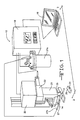
- Figure 1 illustrates a front perspective view of one embodiment of an apparatus 10 for measuring the thickness 12 of a surface 14.
- the surface 14 being measured may comprise an airplane surface, a wing skin, a wing spar, a wing stringer, a metal, an alloy, or another type of surface.
- the apparatus 10 includes a computer 16, a controller 18, a machine 20, a compliance assembly 22, a solenoid assembly 23, a normalizing assembly 25, and a couplant supply device 27.
- the couplant supply device 27 may comprise a couplant supply tank 27a and a couplant line 27b.
- a reference standard 29 made of a known material and having a known thickness 31 may be used to calibrate the apparatus 10 prior to measuring the thickness 12 of the surface 14.
- the computer 16 and/or the controller 18 is used to control and/or to calibrate the apparatus 10 in order to automatically measure the thickness 12 of the surface 14.
- Figure 2 illustrates a cross-section view through line 2-2 of the embodiment of Figure 1 with the apparatus 10 disposed apart from the surface 14.
- the machine 20 may comprise a robot, a milling machine, and/or another type of machine for controlling movement of the apparatus 10.
- the compliance assembly 22 includes a compliance plate 24, a load cell 26, a compliance spring 28, an upper compliance housing 30, and a lower compliance housing 32.
- the solenoid assembly 23 comprises a solenoid housing 34, a solenoid 36, a moveable solenoid member 38, a solenoid plate 40, and a coupler 42.
- the normalizing assembly 25 comprises a member 44, a slide housing 46, an inner housing 48, transducer springs 50, a free-floating transducer housing 52, a free-floating transducer housing retaining member 53, a transducer 54, and a transducer line 56.
- Moveable solenoid member 38 may comprise a moveable solenoid rod.
- Member 44 may comprise a normalizing rod.
- the couplant line 27b may extend between the couplant supply tank 27a and the normalizing assembly 25.
- the computer 16 and/or the controller 18 may control the machine 20.
- the machine 20 may be fixedly attached to the compliance plate 24.
- the compliance plate 24 and the load cell 26 may be fixedly attached to the upper compliance housing 30.
- the upper compliance housing 30 may be moveably attached to the lower compliance housing 32 to allow relative movement between the upper and lower compliance housings 30 and 32 up and down along direction 33.
- the upper compliance housing 30 may be moveably disposed into a cavity 32a of the lower compliance housing 32 using linear slide members 32b to move compliance plate 24 up and down along direction 33 thereby moving the attached upper compliance housing 30 relative to the lower compliance housing 32.
- any type of mechanism may be used to moveably attach the upper compliance housing 30 to the lower compliance housing 32.
- One end 28a of the compliance spring 28 may be fixedly attached to the load cell 26.
- the other end 28b of the compliance spring 28 may be freely disposed.
- the compliance spring 28 may be fully extended.
- the end 28b of the compliance spring 28 may abut against a bottom surface 32c of the lower compliance housing 32 in order to compress the compliance spring 28 towards the load cell 26.
- the solenoid housing 34 may be fixedly attached to the lower compliance housing 32.
- the solenoid 36 may be fixedly attached to the solenoid plate 40 attached to the solenoid housing 34.
- the moveable solenoid member 38 may be moveably attached to the solenoid 36.
- the solenoid 36 may move the moveable solenoid member 38 up and down along direction 37.
- One end 38a of the moveable solenoid member 38 may be attached to the solenoid 36, and the other end 38b of the moveable solenoid member 38 may be attached to the coupler 42.
- One end 44a of the member 44 may be attached to the coupler 42, and another end 44b of the member 44 may be attached to the inner housing 48.
- the solenoid 36 may move the inner housing 48 up and down by moving the moveable solenoid member 38 up and down along direction 37.
- the slide housing 46 may be fixedly attached to the solenoid housing 34.
- the slide housing 46 may comprise a hollow cylinder.
- the free-floating transducer housing retaining member 53 may be fixedly attached to the inner housing 48.
- the transducer springs 50, free-floating transducer housing 52, and transducer 54 may be disposed at least partially within a cavity 48a of the inner housing 48.
- the free-floating transducer housing retaining member 53 may comprise a retaining member ring.
- the free-floating transducer housing retaining member 53 may be defined by angled surfaces 53a forming a hole 53b.
- One end 50a of the transducer springs 50 may be attached to a top surface 48b of the inner cavity 48a of the inner housing 48.
- the other end 50b of the transducer springs 50 may be attached to a top surface 52b of the free-floating transducer housing 52. In this position, the transducer springs 50 may be only partially compressed and the angled surfaces 52c of the free-floating transducer housing 52 may abut in mating arrangement with and against the angled surfaces 53b of the free-floating transducer housing retaining member 53 preventing the free-floating transducer housing 52 from freely floating.
- the transducer 54 may comprise an ultrasonic transducer or another type of transducer. The transducer 54 may be fixedly attached to the free-floating transducer housing 52. A bottom measuring end 54a of the transducer 54 may extend beyond a bottom surface of the free-floating transducer housing 52.
- the bottom measuring end 54a of the transducer 54 when the angled surfaces 52c of the free-floating transducer housing 52 are abutted against the angled surfaces 53b of the free-floating housing retaining member 53 with the transducer springs 50 in a partially compressed position, may extend into and out of the hole 53a of the free-floating housing retaining member 53.
- the couplant line 27b may extend between the couplant supply tank 27a and into the slide housing 46.
- the couplant supply tank 27a may be supply couplant 27c onto the surface 14 below and/or within the slide housing 46.
- the couplant 27c may comprise water or another type of couplant.
- Figure 3 illustrates a cross-section view through line 3-3 of the embodiment of Figure 2 .
- five transducer springs 50 may be distributed around a perimeter 52a of the free-floating transducer housing 52.
- a varying number of transducer springs 50 may be used in varying orientations and/or configurations relative to the inner housing 48 and/or to the free-floating transducer housing 52.
- the computer 16 and/or controller 18 may have instructed the machine 20 to position the slide housing 46 and the transducer 54 apart from the surface 14.
- the upper compliance housing 30 may be disposed in a raised position relative to the lower compliance housing 32 so that only a small portion of the upper compliance housing 30 is disposed within the cavity 32a of the lower compliance housing 32, while the compliance spring 28 may be in an extended position apart from the bottom surface 32c of the lower compliance housing 32.
- the moveable solenoid member 38 may be disposed in a raised position causing the inner housing 48 and the attached free-floating transducer housing retaining member 53 to be in a raised position within the slide housing 46.
- the free-floating transducer housing 52 which is abutted against the free-floating transducer housing retaining member 53, and the attached transducer 54 may also be in a raised position at least partly within the cavity 48a of the inner housing 48.
- Figure 4 illustrates the cross-section view of the embodiment of Figure 2 with the slide housing 46 of the apparatus 10 having been moved against the surface 14.
- the computer 16 and/or controller 18 may have instructed the machine 20 to have moved the compliance plate 24 downward causing the compliance assembly 22, the solenoid assembly 23, and the slide housing 46 to move downward to position the slide-housing 46 against the surface 14.
- the force of the surface 14 may have caused the upper compliance housing 30 to have moved towards the bottom surface 32c of the lower compliance housing 32.
- the end 28b of the compliance spring 28 may have abutted against the bottom surface 32c of the lower compliance housing 32 thereby compressing the compliance spring 28 towards the load cell 26.
- the load cell 26 may have measured the compression of the compliance spring 28, and may have stopped the machine 20 from further moving the slide housing 46 against the surface 14 when the amount of force applied by the slide housing 46 against the surface 14 reached a desired amount of force for the surface 14 being measured.
- the desired amount of force may have been based on the material of the surface 14 and/or other factors. In such manner, the load cell 26 may avoid the surface 14 and/or the slide housing 46 from being damaged.
- the solenoid 36 may have kept the moveable solenoid member 38 in a raised position, while the slide housing 46 abutted against the surface 14, so that the inner housing 48, the attached free-floating transducer housing retaining member 53, the free-floating transducer housing 52, and the transducer 54 remained in their raised positions within the slide housing 46. In such manner, the transducer 54 may remain disposed apart from the surface 14 in a raised position inside the slide housing 46.
- the computer 16 and/or controller 18 may have instructed the couplant supply tank 27a (not shown in Figure 4 ) to dispose couplant 27c onto the surface 14 within and/or below the slide housing 46 with the transducer 54 in the raised position within the slide housing 46.
- Figure 5 illustrates the cross-section view of the embodiment of Figure 4 with the transducer 54 within the slide housing 46 having been moved against the surface 14.
- the computer 16 and/or controller 18 may have instructed the solenoid 36 to have moved the moveable solenoid member 38 downward towards the surface 14. This may have caused the inner housing 48, attached to the moveable solenoid member 38 with the coupler 42 and the member 44, and the attached free-floating transducer housing retaining member 53 to have moved relative to and within the slide housing 46 towards the surface 14.
- the downward movement of the inner housing 48 may have caused a bottom measuring surface 54a of the transducer 54, sticking out of the hole 53a of the free-floating transducer housing retaining member 53, to abut against the surface 14.
- the force of the surface 14 against the bottom measuring surface 54a of the transducer 54 may have forced the angled surfaces 52c of the attached free-floating transducer housing 52 to have moved upwardly to separate from the angled surfaces 53b of the free-floating transducer housing retaining member 53.
- the transducer springs 50 may have further compressed upwardly allowing the free-floating transducer housing 52 and the attached transducer 54 to freely float apart from and relative to the free-floating transducer housing retaining member 53.
- the free-floating transducer housing 52 and the attached transducer 54 may freely move in varying directions and orientations, by moving up and down, sideways, at an angle, and/or rotating in order to orient the bottom measuring surface 54a of the transducer 54 to be substantially parallel to and against the surface 14 to be measured by the transducer.
- the transducer 54 may have taken measurements of the thickness of the surface 14 by emitting an ultrasonic signal 60, reflecting the ultrasonic signal 60 off a bottom surface 14a of the surface 14, and receiving the reflected ultrasonic signal 60.
- the free-floating transducer housing 52 may allow the bottom measuring surface 54a of the transducer 54 to be rotated from between three to five degrees relative to the surface 14 and still take accurate measurements of the thickness 12 of the surface 14.
- the free-floating transducer housing 52 may allow the bottom measuring surface 54a of the transducer 54 to be rotated in varying amounts while still taking accurate measurements of the thickness 12 of the surface 14.
- the computer 16 may calculate the thickness 12 of the surface 14 based on the measurements taken by the transducer 54.
- the computer 16 may calculate the thickness 12 of the surface 14 based on a known velocity of the ultrasonic signal 60, a known material of the surface 14, and a time of flight of the ultrasonic signal 60 between the transducer 54 and the surface 14.
- the computer 16 may store the measurements of the thickness 12 of the surface 14, and may determine if the thickness 12 of the surface 14 meets tolerance standards. Based on the determination, the surface 14 may be accepted or rejected.
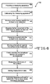
- FIG. 6 illustrates a flowchart of one embodiment of a method 162 of automatically measuring a surface 14.
- the surface 14 may comprise an airplane surface, a wing skin, a wing spar, a wing stringer, or another type of surface.
- a measuring apparatus 10 is provided.
- the provided measuring apparatus 10 comprises a computer 16, machine 20, a load cell 26, a solenoid 36, a slide housing 46, an inner housing 48, a fee-floating transducer housing retaining member 53 attached to the inner housing 48, a transducer 54 attached to a free-floating transducer housing 52, transducer springs 50 attached between the free-floating transducer housing 52 and the inner housing 48, and a couplant supply device 27.
- the machine 20 may comprise a milling machine, a robot, and/or another type of machine.
- the transducer 54 may comprise an ultrasonic transducer or another type of transducer.
- the provided measuring apparatus 10 may comprise any of the embodiments disclosed herein.
- the measuring apparatus 10 is calibrated using a reference standard 29 and at least one of the computer 16 and a controller 18.
- the reference standard 29 may comprise a known thickness 31 and a known material.
- the slide housing 46 is moved against the surface 14 to be measured using the machine 20.
- step 170 further movement of the slide housing 46 against the surface 14 to be measured is stopped based on calculations of the load cell 26 regarding an amount of force applied by the slide housing 46 against the surface 14.
- step 172 couplant 27c is disposed onto the surface 14 to be measured using the couplant supply device 27.
- step 174 the transducer 54 is moved against the surface 14 to be measured using a moveable solenoid member 38 of the solenoid 36.
- Step 174 may comprise the moveable solenoid member 38 moving the inner housing 48 relative to the slide housing 46.
- step 176 a bottom measuring surface 54a of the transducer 54 is freely oriented substantially parallel to and against the surface 14 to be measured as a result of the free-floating transducer housing 52.
- Step 176 may comprise the free-floating transducer housing 52 separating from the free-floating transducer housing retaining member 53 to compress the transducer springs 50 and to orient the bottom measuring surface 54a of the transducer 54 substantially parallel to and against the surface 14 to be measured.
- Step 178 a thickness 12 of the surface 14 is measured using the transducer 54.
- Step 178 may comprise emitting an ultrasonic signal 60 from the ultrasonic transducer 54, reflecting the ultrasonic signal 60 off a bottom surface 14a of the surface 14, receiving the reflected ultrasonic signal 60 with the ultrasonic transducer 54, and calculating the thickness 12 of the surface 14 based on a known velocity of the ultrasonic signal 60, based on a known material of the surface 14, and based on a time of flight of the ultrasonic signal 60 between the ultrasonic transducer 54 and the surface 14.
- step 180 measurement data regarding the thickness 12 of the surface 14 is stored using the computer 16.
- step 183 the stored measurement data is analyzed to determine if the surface 14 meets tolerance standards in order to accept or reject the surface 14.
- one or more of the steps of the method 162 may be changed in order, deleted, or altered.
- varying steps may be added.
- the steps of the method 162 may be done automatically in less than two seconds. In other embodiments, the steps of the method 162 may be done automatically in varying amounts of time.
- One or more embodiments of the disclosure may reduce or eliminate one or more problems associated with one or more of the conventional apparatus and/or methods for measuring the thickness of a surface. For instance, one or more embodiments of the disclosure may: allow a surface to be automatically measured in less than two seconds thereby saving time, saving labor, saving cost, and reducing the likelihood of a couplant oxiding the surface; may allow for angular deviations of the transducer while still taking accurate measurements of the surface; may be completely automated and computer-controlled thereby increasing accuracy and reducing or eliminating repetitive injuries to operators; may reduce the need for extra manufacturing processes due to the resulting increased tolerance-accuracy of measured surfaces; or may reduce and/or eliminate other types of problems.
Landscapes
- Physics & Mathematics (AREA)
- General Physics & Mathematics (AREA)
- Length Measuring Devices Characterised By Use Of Acoustic Means (AREA)
Claims (15)
- Vorrichtung (10) zum Messen der Dicke einer Oberfläche (14), wobei die Vorrichtung Folgendes aufweist:- eine Normalsierungsanordnung (25), die einen zum Messen einer Dicke durch Kontaktieren einer Oberfläche geeigneten Messwandler (54), ein Messwandlergehäuse (52), Messwandlerfedern (50), ein inneres Gehäuse (48) und ein Führungsgehäuse (46) aufweist, wobei der Messwandler (54) an dem Messwandlergehäuse (52) angebracht ist, die Messwandlerfedern (50) zwischen dem Messwandlergehäuse (52) und dem inneren Gehäuse (48) angebracht sind, und das innere Gehäuse (48) verschiebbar angeordnet ist und sich so zumindest teilweise innerhalb des Führungsgehäuses (46) befindet, dass das Messwandlergehäuse (52) innerhalb des inneren Gehäuses (48) frei verschiebbar ist;- eine Elektromagnetenanordnung (23), die einen Elektromagneten (36) und ein verschiebbares Elektromagnetenelement (38) aufweist, wobei der Elektromagnet (36) und das verschiebbare Elektromagnetenelement (38) so zum Verschieben des inneren Gehäuses (48) relativ zum Führungsgehäuse (46) ausgebildet sind, dass der Messwandler (54) gegen die zu messende Oberfläche (14) verschoben werden kann; und- eine Rückstellanordnung (22), die eine Kraftmesszelle (26) und zumindest ein Rückstellgehäuse (30, 32) aufweist, wobei die Kraftmesszelle (26) zum Messen der von der zu messenden Oberfläche (14) auf das Führungsgehäuse (46) ausgeübten Kraft ausgebildet ist.
- Vorrichtung nach Anspruch 1, die ferner eine Kopplungsmittelaufbringungsvorrichtung zum Aufbringen eines Kopplungsmittels auf eine mithilfe der Messwandlervorrichtung zu messenden Oberfläche aufweist.
- Vorrichtung nach Anspruch 1, worin die Normalisierungsanordnung ferner ein an dem inneren Gehäuse angebrachtes Halteelement für das frei verschiebbare Messwandlergehäuse aufweist, wobei das Halteelement für das frei verschiebbare Messwandlergehäuse durch ein Loch bestimmt ist, das schräge Oberflächen aufweist, die sich an die schrägen Oberflächen des frei verschiebbaren Messwandlergehäuses angepasst an diese anlegen, wenn das frei verschiebbare Messwandlergehäuse sich nicht in einer frei verschiebbaren Position befindet.
- Vorrichtung nach Anspruch 1, worin zwischen dem frei verschiebbaren Messwandlergehäuse und dem inneren Gehäuse fünf Messwandlerfedern angebracht sind.
- Vorrichtung nach Anspruch 1, worin das verschiebbare Elektromagnetenelement eine an einer Kupplung angebrachte Betätigungsstange aufweist, die Kupplung an einer anderen Stange angebracht ist und die andere Stange an dem inneren Gehäuse angebracht ist.
- Vorrichtung nach Anspruch 1, worin der Messwandler einen Ultraschallwandler aufweist und der Messkopf des Ultraschallwandlers über eine untere Oberfläche des frei verschiebbaren Messwandlergehäuses hinausreicht.
- Vorrichtung nach Anspruch 1, worin die Rückstellanordnung eine oberes Rückstellgehäuse, ein unteres Rückstellgehäuse und eine Rückstellfeder aufweist, und worin das obere und das untere Rückstellgehäuse relativ zueinander verschiebbar angeordnet sind und die Rückstellfeder bei Relativbewegungen des oberen zum unteren Gehäuse gestaucht und gedehnt wird.
- Vorrichtung nach Anspruch 1, die ferner eine Apparatur und/oder einen Automaten und/oder eine Fräsvorrichtung zum Verschieben der Normalisierungsanordnung, der Elektromagnetenanordnung und der Rückstellanordnung relativ zur zu messenden Oberfläche aufweist.
- Vorrichtung nach Anspruch 1, die ferner einen Computer und/oder eine Steuerung zum Speichern der mit der Vorrichtung gemessenen Dickendaten und/oder zum Kalibrieren der Vorrichtung und/oder zum Steuern der Vorrichtung aufweist.
- Verfahren zum automatischen Messen der Dicke einer Oberfläche (14), wobei das Verfahren Folgendes aufweist:- Bereitstellen einer Messvorrichtung (10) nach Anspruch 1, die ein Führungsgehäuse (46), eine Apparatur (20), eine Kraftmesszelle (26), eine Kopplungsmittelaufbringungsvorrichtung (27), einen Elektromagneten (36), einen Messwandler (54), ein frei verschiebbares Messwandlergehäuse (52) und einen Computer (16) aufweist;- Verschieben des Führungsgehäuses (46) gegen die zu messende Oberfläche (14) unter Verwendung der Apparatur (20);- Beenden eines weiteren Verschiebens des Führungsgehäuses (46) in Richtung der zu messenden Oberfläche (14) gestützt auf Ermittlungen der Kraftmesszelle (26) bezüglich einer Stärke der von dem Führungsgehäuse (46) auf die Oberfläche (14) ausgeübten Kraft;- Aufbringen von Kopplungsmittel auf die zu messende Oberfläche (14) unter Verwendung der Kopplungsmittelaufbringungsvorrichtung (27);- Verschieben des Messwandlers (54) in Richtung der zu messenden Oberfläche (14) unter Verwendung eines verschiebbaren Elektromagnetenelements (38) des Elektromagneten (36);- Ausrichten einer Messwandleroberfläche des Messwandlers (54) im Wesentlichen parallel zu in Richtung der zu messenden Oberfläche (14) unter Verwendung des frei verschiebbaren Messwandlergehäuses (52);- Messen einer Dicke der Oberfläche (14) unter Verwendung des Messwandlers (54); und- Speichern von Messdaten bezüglich der Oberflächendicke (14) unter Verwendung des Computers (16).
- Verfahren nach Anspruch 10, das ferner einen Schritt zum Analysieren der gespeicherten Messdaten aufweist, um zu bestimmen, ob die Oberfläche einer Toleranzanforderung genügt.
- Verfahren nach Anspruch 10, das ferner einen Schritt zum Kalibrieren der Messvorrichtung unter Verwendung eines Referenzstandards und eines Computers und/oder einer Steuerung aufweist, wobei der Referenzstandard ein bekanntes Material mit einer bekannten Dicke umfasst.
- Verfahren nach Anspruch 10, worin die Apparatur eine Fräsvorrichtung und/oder einen Automaten aufweist.
- Verfahren nach Anspruch 10, worin die bereitgestellte Messvorrichtung ferner ein inneres Gehäuse aufweist und der Schritt zum Verschieben des Messwandlers ferner ein Verschieben des inneren Gehäuses durch das verschiebbare Elektromagnetenelement relativ zum Führungsgehäuse umfasst.
- Verfahren nach Anspruch 10, worin der Messwandler der bereitgestellten Messvorrichtung einen Ultraschallwandler aufweist und der Schritt zum Messen der Dicke ein Aussenden eines Ultraschallsignals von dem Ultraschallwandler, Reflektieren des Ultraschallsignals an einer unteren Oberfläche der Oberfläche, Empfangen des reflektierten Ultraschallsignals mit dem Ultraschallwandler und Berechnen der Dicke der Oberfläche gestützt auf eine bekannte Geschwindigkeit des Ultraschallsignals, einem bekannten Material der Oberfläche und einer Laufzeit des Ultraschallsignals zwischen dem Messwandler und der Oberfläche umfasst.
Applications Claiming Priority (1)
| Application Number | Priority Date | Filing Date | Title |
|---|---|---|---|
| US12/394,471 US8104350B2 (en) | 2009-02-27 | 2009-02-27 | Automated thickness measurement device |
Publications (2)
| Publication Number | Publication Date |
|---|---|
| EP2224203A1 EP2224203A1 (de) | 2010-09-01 |
| EP2224203B1 true EP2224203B1 (de) | 2011-06-22 |
Family
ID=42237048
Family Applications (1)
| Application Number | Title | Priority Date | Filing Date |
|---|---|---|---|
| EP10250310A Active EP2224203B1 (de) | 2009-02-27 | 2010-02-22 | Automatisierte Dickenmessvorrichtung |
Country Status (4)
| Country | Link |
|---|---|
| US (1) | US8104350B2 (de) |
| EP (1) | EP2224203B1 (de) |
| AT (1) | ATE514047T1 (de) |
| ES (1) | ES2365665T3 (de) |
Families Citing this family (3)
| Publication number | Priority date | Publication date | Assignee | Title |
|---|---|---|---|---|
| IT1399605B1 (it) | 2010-04-14 | 2013-04-26 | Esaote Spa | Metodo per la misurazione dello spessore di un tessuto biologico tramite ultrasuoni e dispositivo per attuare tale metodo. |
| NL2020338B1 (en) * | 2018-01-29 | 2019-08-02 | Acquaint B V | Method for measuring cement elements, such as piping, and measurement system there for |
| EP4227639A1 (de) * | 2022-02-09 | 2023-08-16 | Renishaw plc | Ultraschallprüfsonde für eine werkzeugmaschine |
Family Cites Families (8)
| Publication number | Priority date | Publication date | Assignee | Title |
|---|---|---|---|---|
| US3205702A (en) * | 1963-12-30 | 1965-09-14 | Chemetron Corp | Ultrasonic coupling device |
| FR2172808B1 (de) * | 1972-02-22 | 1978-09-29 | Inst Francais Du Petrole | |
| DE2743394C3 (de) * | 1977-09-27 | 1980-06-26 | Endress U. Hauser Gmbh U. Co, 7867 Maulburg | Vorrichtung zur Befestigung eines für die Füllstandsmessung bestimmten Schall- oder Ultraschallwandlers an einem Behälter |
| NL8200586A (nl) * | 1982-02-16 | 1983-09-16 | Fokker Bv | Omzetter van elektrische in mechanische trillingen ten behoeve van het niet-destructief onderzoek van objecten. |
| US5507185A (en) * | 1993-03-16 | 1996-04-16 | Southwest Research Institute | Adaptive scanning technique for ultrasonic testing utilizing realtime lift-off detection |
| US5549004A (en) * | 1995-02-28 | 1996-08-27 | Nugent; Michael J. | Hand held tube wall thickness ultrasonic measurement probe and system |
| DE10302312B4 (de) | 2003-01-20 | 2005-03-10 | Daimler Chrysler Ag | Sensoranordnung und Roboteranordnung zur Positionierung de Meßsensoranordnung |
| US7249512B2 (en) * | 2005-01-24 | 2007-07-31 | The Boeing Company | Non-destructive stringer inspection apparatus and method |
-
2009
- 2009-02-27 US US12/394,471 patent/US8104350B2/en active Active
-
2010
- 2010-02-22 EP EP10250310A patent/EP2224203B1/de active Active
- 2010-02-22 ES ES10250310T patent/ES2365665T3/es active Active
- 2010-02-22 AT AT10250310T patent/ATE514047T1/de not_active IP Right Cessation
Also Published As
| Publication number | Publication date |
|---|---|
| ATE514047T1 (de) | 2011-07-15 |
| US20100218590A1 (en) | 2010-09-02 |
| ES2365665T3 (es) | 2011-10-10 |
| EP2224203A1 (de) | 2010-09-01 |
| US8104350B2 (en) | 2012-01-31 |
Similar Documents
| Publication | Publication Date | Title |
|---|---|---|
| US5189808A (en) | Measurement gauge | |
| US8347746B2 (en) | Crawling automated scanner for non-destructive inspection of aerospace structural elements | |
| CN108015312B (zh) | 用于机器人高精度制孔与锪窝的末端执行器及测量方法 | |
| KR102168442B1 (ko) | 스트링거의 비파괴 검사 장치 | |
| CN107322930B (zh) | 一种具有检测现有工件功能的3d打印机 | |
| US9594059B1 (en) | System and method for automated bond testing | |
| EP2224203B1 (de) | Automatisierte Dickenmessvorrichtung | |
| EP3838767A1 (de) | Schadensbeurteilungsvorrichtung zur ferngesteuerten inspektion von flugzeugen | |
| CN111331431B (zh) | 接触式曲面壁板法向测量与锪窝深度补偿装置及测量方法 | |
| CN102507344A (zh) | 一种和变形速度关联的金属板料杯突试验方法 | |
| KR20070074463A (ko) | 항공기 기체의 검사 방법 및 장치 | |
| US9086386B1 (en) | Sensor coupling apparatus | |
| CN101520321B (zh) | 精度检测设备 | |
| CN114942200A (zh) | 一种蜂窝材料超声加工直刃刀锋利度分析方法 | |
| CN112050744A (zh) | 轴承装配高尺寸检测仪器 | |
| CN107560584B (zh) | 一种主动齿轮零件专用检具 | |
| CN102589783A (zh) | 智能型飞机载荷机构通用测试系统 | |
| CN207976126U (zh) | 一种用于检测精密工件的高度仪 | |
| CN208520320U (zh) | 一种金属板规格检测治具 | |
| CN117606327A (zh) | 一种航空发动机叶片型面检测设备 | |
| US20190360973A1 (en) | Ultrasonic cap radius probe providing constant fluid path length | |
| CN114800606A (zh) | 一种连续体机械臂直线距离传感器标定系统及标定方法 | |
| EP2893339B1 (de) | Schwebender kopfkonturverfolgungshalter für ultraschalluntersuchung | |
| CN113251971B (zh) | 一种汽车扶手箱用自动检测设备 | |
| CN223711251U (zh) | 一种高精准便携微压痕检测仪 |
Legal Events
| Date | Code | Title | Description |
|---|---|---|---|
| PUAI | Public reference made under article 153(3) epc to a published international application that has entered the european phase |
Free format text: ORIGINAL CODE: 0009012 |
|
| 17P | Request for examination filed |
Effective date: 20100319 |
|
| AK | Designated contracting states |
Kind code of ref document: A1 Designated state(s): AT BE BG CH CY CZ DE DK EE ES FI FR GB GR HR HU IE IS IT LI LT LU LV MC MK MT NL NO PL PT RO SE SI SK SM TR |
|
| AX | Request for extension of the european patent |
Extension state: AL BA RS |
|
| GRAP | Despatch of communication of intention to grant a patent |
Free format text: ORIGINAL CODE: EPIDOSNIGR1 |
|
| RIC1 | Information provided on ipc code assigned before grant |
Ipc: G01B 21/08 20060101ALI20101214BHEP Ipc: G01B 17/02 20060101ALI20101214BHEP Ipc: G01B 5/00 20060101AFI20101214BHEP |
|
| GRAS | Grant fee paid |
Free format text: ORIGINAL CODE: EPIDOSNIGR3 |
|
| GRAA | (expected) grant |
Free format text: ORIGINAL CODE: 0009210 |
|
| AK | Designated contracting states |
Kind code of ref document: B1 Designated state(s): AT BE BG CH CY CZ DE DK EE ES FI FR GB GR HR HU IE IS IT LI LT LU LV MC MK MT NL NO PL PT RO SE SI SK SM TR |
|
| REG | Reference to a national code |
Ref country code: GB Ref legal event code: FG4D |
|
| REG | Reference to a national code |
Ref country code: CH Ref legal event code: EP |
|
| REG | Reference to a national code |
Ref country code: IE Ref legal event code: FG4D |
|
| REG | Reference to a national code |
Ref country code: DE Ref legal event code: R096 Ref document number: 602010000081 Country of ref document: DE Effective date: 20110804 |
|
| REG | Reference to a national code |
Ref country code: ES Ref legal event code: FG2A Ref document number: 2365665 Country of ref document: ES Kind code of ref document: T3 Effective date: 20111010 |
|
| REG | Reference to a national code |
Ref country code: NL Ref legal event code: VDEP Effective date: 20110622 |
|
| PG25 | Lapsed in a contracting state [announced via postgrant information from national office to epo] |
Ref country code: HR Free format text: LAPSE BECAUSE OF FAILURE TO SUBMIT A TRANSLATION OF THE DESCRIPTION OR TO PAY THE FEE WITHIN THE PRESCRIBED TIME-LIMIT Effective date: 20110622 Ref country code: SE Free format text: LAPSE BECAUSE OF FAILURE TO SUBMIT A TRANSLATION OF THE DESCRIPTION OR TO PAY THE FEE WITHIN THE PRESCRIBED TIME-LIMIT Effective date: 20110622 Ref country code: LT Free format text: LAPSE BECAUSE OF FAILURE TO SUBMIT A TRANSLATION OF THE DESCRIPTION OR TO PAY THE FEE WITHIN THE PRESCRIBED TIME-LIMIT Effective date: 20110622 Ref country code: NO Free format text: LAPSE BECAUSE OF FAILURE TO SUBMIT A TRANSLATION OF THE DESCRIPTION OR TO PAY THE FEE WITHIN THE PRESCRIBED TIME-LIMIT Effective date: 20110922 |
|
| PG25 | Lapsed in a contracting state [announced via postgrant information from national office to epo] |
Ref country code: GR Free format text: LAPSE BECAUSE OF FAILURE TO SUBMIT A TRANSLATION OF THE DESCRIPTION OR TO PAY THE FEE WITHIN THE PRESCRIBED TIME-LIMIT Effective date: 20110923 Ref country code: SI Free format text: LAPSE BECAUSE OF FAILURE TO SUBMIT A TRANSLATION OF THE DESCRIPTION OR TO PAY THE FEE WITHIN THE PRESCRIBED TIME-LIMIT Effective date: 20110622 Ref country code: AT Free format text: LAPSE BECAUSE OF FAILURE TO SUBMIT A TRANSLATION OF THE DESCRIPTION OR TO PAY THE FEE WITHIN THE PRESCRIBED TIME-LIMIT Effective date: 20110622 Ref country code: CY Free format text: LAPSE BECAUSE OF FAILURE TO SUBMIT A TRANSLATION OF THE DESCRIPTION OR TO PAY THE FEE WITHIN THE PRESCRIBED TIME-LIMIT Effective date: 20110622 Ref country code: LV Free format text: LAPSE BECAUSE OF FAILURE TO SUBMIT A TRANSLATION OF THE DESCRIPTION OR TO PAY THE FEE WITHIN THE PRESCRIBED TIME-LIMIT Effective date: 20110622 Ref country code: FI Free format text: LAPSE BECAUSE OF FAILURE TO SUBMIT A TRANSLATION OF THE DESCRIPTION OR TO PAY THE FEE WITHIN THE PRESCRIBED TIME-LIMIT Effective date: 20110622 |
|
| PG25 | Lapsed in a contracting state [announced via postgrant information from national office to epo] |
Ref country code: NL Free format text: LAPSE BECAUSE OF FAILURE TO SUBMIT A TRANSLATION OF THE DESCRIPTION OR TO PAY THE FEE WITHIN THE PRESCRIBED TIME-LIMIT Effective date: 20110622 Ref country code: BE Free format text: LAPSE BECAUSE OF FAILURE TO SUBMIT A TRANSLATION OF THE DESCRIPTION OR TO PAY THE FEE WITHIN THE PRESCRIBED TIME-LIMIT Effective date: 20110622 |
|
| PG25 | Lapsed in a contracting state [announced via postgrant information from national office to epo] |
Ref country code: CZ Free format text: LAPSE BECAUSE OF FAILURE TO SUBMIT A TRANSLATION OF THE DESCRIPTION OR TO PAY THE FEE WITHIN THE PRESCRIBED TIME-LIMIT Effective date: 20110622 Ref country code: PT Free format text: LAPSE BECAUSE OF FAILURE TO SUBMIT A TRANSLATION OF THE DESCRIPTION OR TO PAY THE FEE WITHIN THE PRESCRIBED TIME-LIMIT Effective date: 20111024 Ref country code: IS Free format text: LAPSE BECAUSE OF FAILURE TO SUBMIT A TRANSLATION OF THE DESCRIPTION OR TO PAY THE FEE WITHIN THE PRESCRIBED TIME-LIMIT Effective date: 20111022 Ref country code: EE Free format text: LAPSE BECAUSE OF FAILURE TO SUBMIT A TRANSLATION OF THE DESCRIPTION OR TO PAY THE FEE WITHIN THE PRESCRIBED TIME-LIMIT Effective date: 20110622 |
|
| PG25 | Lapsed in a contracting state [announced via postgrant information from national office to epo] |
Ref country code: SK Free format text: LAPSE BECAUSE OF FAILURE TO SUBMIT A TRANSLATION OF THE DESCRIPTION OR TO PAY THE FEE WITHIN THE PRESCRIBED TIME-LIMIT Effective date: 20110622 Ref country code: PL Free format text: LAPSE BECAUSE OF FAILURE TO SUBMIT A TRANSLATION OF THE DESCRIPTION OR TO PAY THE FEE WITHIN THE PRESCRIBED TIME-LIMIT Effective date: 20110622 |
|
| PLBE | No opposition filed within time limit |
Free format text: ORIGINAL CODE: 0009261 |
|
| STAA | Information on the status of an ep patent application or granted ep patent |
Free format text: STATUS: NO OPPOSITION FILED WITHIN TIME LIMIT |
|
| 26N | No opposition filed |
Effective date: 20120323 |
|
| PG25 | Lapsed in a contracting state [announced via postgrant information from national office to epo] |
Ref country code: DK Free format text: LAPSE BECAUSE OF FAILURE TO SUBMIT A TRANSLATION OF THE DESCRIPTION OR TO PAY THE FEE WITHIN THE PRESCRIBED TIME-LIMIT Effective date: 20110622 |
|
| REG | Reference to a national code |
Ref country code: DE Ref legal event code: R097 Ref document number: 602010000081 Country of ref document: DE Effective date: 20120323 |
|
| REG | Reference to a national code |
Ref country code: DE Ref legal event code: R409 Ref document number: 602010000081 Country of ref document: DE |
|
| PG25 | Lapsed in a contracting state [announced via postgrant information from national office to epo] |
Ref country code: MC Free format text: LAPSE BECAUSE OF NON-PAYMENT OF DUE FEES Effective date: 20120229 |
|
| REG | Reference to a national code |
Ref country code: IE Ref legal event code: MM4A |
|
| REG | Reference to a national code |
Ref country code: DE Ref legal event code: R119 Ref document number: 602010000081 Country of ref document: DE Effective date: 20120901 |
|
| PG25 | Lapsed in a contracting state [announced via postgrant information from national office to epo] |
Ref country code: IE Free format text: LAPSE BECAUSE OF NON-PAYMENT OF DUE FEES Effective date: 20120222 |
|
| PG25 | Lapsed in a contracting state [announced via postgrant information from national office to epo] |
Ref country code: MK Free format text: LAPSE BECAUSE OF FAILURE TO SUBMIT A TRANSLATION OF THE DESCRIPTION OR TO PAY THE FEE WITHIN THE PRESCRIBED TIME-LIMIT Effective date: 20110622 |
|
| PG25 | Lapsed in a contracting state [announced via postgrant information from national office to epo] |
Ref country code: DE Free format text: LAPSE BECAUSE OF NON-PAYMENT OF DUE FEES Effective date: 20120901 Ref country code: BG Free format text: LAPSE BECAUSE OF FAILURE TO SUBMIT A TRANSLATION OF THE DESCRIPTION OR TO PAY THE FEE WITHIN THE PRESCRIBED TIME-LIMIT Effective date: 20110922 |
|
| REG | Reference to a national code |
Ref country code: DE Ref legal event code: R409 Ref document number: 602010000081 Country of ref document: DE |
|
| PG25 | Lapsed in a contracting state [announced via postgrant information from national office to epo] |
Ref country code: MT Free format text: LAPSE BECAUSE OF FAILURE TO SUBMIT A TRANSLATION OF THE DESCRIPTION OR TO PAY THE FEE WITHIN THE PRESCRIBED TIME-LIMIT Effective date: 20110622 |
|
| PG25 | Lapsed in a contracting state [announced via postgrant information from national office to epo] |
Ref country code: TR Free format text: LAPSE BECAUSE OF FAILURE TO SUBMIT A TRANSLATION OF THE DESCRIPTION OR TO PAY THE FEE WITHIN THE PRESCRIBED TIME-LIMIT Effective date: 20110622 |
|
| PG25 | Lapsed in a contracting state [announced via postgrant information from national office to epo] |
Ref country code: LU Free format text: LAPSE BECAUSE OF NON-PAYMENT OF DUE FEES Effective date: 20120222 Ref country code: SM Free format text: LAPSE BECAUSE OF FAILURE TO SUBMIT A TRANSLATION OF THE DESCRIPTION OR TO PAY THE FEE WITHIN THE PRESCRIBED TIME-LIMIT Effective date: 20110622 |
|
| PGRI | Patent reinstated in contracting state [announced from national office to epo] |
Ref country code: DE Effective date: 20130702 |
|
| PG25 | Lapsed in a contracting state [announced via postgrant information from national office to epo] |
Ref country code: HU Free format text: LAPSE BECAUSE OF FAILURE TO SUBMIT A TRANSLATION OF THE DESCRIPTION OR TO PAY THE FEE WITHIN THE PRESCRIBED TIME-LIMIT Effective date: 20100222 |
|
| REG | Reference to a national code |
Ref country code: CH Ref legal event code: PL |
|
| PG25 | Lapsed in a contracting state [announced via postgrant information from national office to epo] |
Ref country code: CH Free format text: LAPSE BECAUSE OF NON-PAYMENT OF DUE FEES Effective date: 20140228 Ref country code: LI Free format text: LAPSE BECAUSE OF NON-PAYMENT OF DUE FEES Effective date: 20140228 |
|
| REG | Reference to a national code |
Ref country code: FR Ref legal event code: PLFP Year of fee payment: 7 |
|
| REG | Reference to a national code |
Ref country code: FR Ref legal event code: PLFP Year of fee payment: 8 |
|
| REG | Reference to a national code |
Ref country code: FR Ref legal event code: PLFP Year of fee payment: 9 |
|
| P01 | Opt-out of the competence of the unified patent court (upc) registered |
Effective date: 20230516 |
|
| PGFP | Annual fee paid to national office [announced via postgrant information from national office to epo] |
Ref country code: GB Payment date: 20260227 Year of fee payment: 17 |
|
| PGFP | Annual fee paid to national office [announced via postgrant information from national office to epo] |
Ref country code: ES Payment date: 20260302 Year of fee payment: 17 |
|
| PGFP | Annual fee paid to national office [announced via postgrant information from national office to epo] |
Ref country code: DE Payment date: 20260227 Year of fee payment: 17 |
|
| PGFP | Annual fee paid to national office [announced via postgrant information from national office to epo] |
Ref country code: IT Payment date: 20260219 Year of fee payment: 17 |
|
| PGFP | Annual fee paid to national office [announced via postgrant information from national office to epo] |
Ref country code: FR Payment date: 20260225 Year of fee payment: 17 |