EP2224362A1 - Procédé d'évaluation de comportement d'absorption d'articles absorbants - Google Patents
Procédé d'évaluation de comportement d'absorption d'articles absorbants Download PDFInfo
- Publication number
- EP2224362A1 EP2224362A1 EP09153881A EP09153881A EP2224362A1 EP 2224362 A1 EP2224362 A1 EP 2224362A1 EP 09153881 A EP09153881 A EP 09153881A EP 09153881 A EP09153881 A EP 09153881A EP 2224362 A1 EP2224362 A1 EP 2224362A1
- Authority
- EP
- European Patent Office
- Prior art keywords
- fluid
- swellable
- composite material
- absorbent article
- swellable composite
- Prior art date
- Legal status (The legal status is an assumption and is not a legal conclusion. Google has not performed a legal analysis and makes no representation as to the accuracy of the status listed.)
- Withdrawn
Links
Images


Classifications
-
- G—PHYSICS
- G06—COMPUTING OR CALCULATING; COUNTING
- G06F—ELECTRIC DIGITAL DATA PROCESSING
- G06F30/00—Computer-aided design [CAD]
- G06F30/20—Design optimisation, verification or simulation
- G06F30/23—Design optimisation, verification or simulation using finite element methods [FEM] or finite difference methods [FDM]
-
- G—PHYSICS
- G06—COMPUTING OR CALCULATING; COUNTING
- G06F—ELECTRIC DIGITAL DATA PROCESSING
- G06F2111/00—Details relating to CAD techniques
- G06F2111/10—Numerical modelling
Definitions
- the present invention relates to a method for designing an absorbent article, and in particular its absorption behaviour and swelling behaviour, using a specific model and a system using said model and a computer.
- the substance may be a fluid containing only a single constituent, such as water.
- the substance may be a multi-phase fluid such as human menstrual fluid, animal menses or bowel movement material.
- testing of prototypes of absorbent articles exposed to substances comprising multiple components in multiple phases can be problematic, because the designer of the absorbent article may be unable to identify the particular impacts of specific phenomena on the performance of the absorbent article.
- the testing equipment used to test absorbent articles is often designed to test the absorbency with respect to clean water, rather than a substance containing a variety of solid, organic or inorganic fluid, and gaseous phases.
- the fluid transport properties of absorbent materials commonly used in absorbent articles can be difficult to measure.
- Key fluid transport properties which partially describe interactions between the absorbent and fluid, include the capillary pressure as a function of saturation and the relative permeability as function of saturation. However, some of these properties are not constant over time or throughout a product. Most commonly used methods for measuring the absorbent-fluid interaction properties are not suitable for testing with fluids other than water. Thus, there is a continuing unaddressed need for methods for developing absorbent articles that integrates physical measurements of the absorbent properties of absorbent materials into the design process.
- Copending US application 11/504993 describes a model and method to design articles with a certain fluid acquisition, solving the equation of continuity and partially saturated flow in porous media (also known as the Richard's equation).
- fluid-swellable material also called superabsorbent material or hydrogel-forming
- hydrogel-forming that absorb liquid due to an osmotic pressure gradients between the material and the surrounding fluid, and that subsequently swell upon absorption
- the traditional Richard's equation is no longer sufficient to describe correctly the fluid flow through the swelling structure formed by the particles.
- the swelling process is an important factor because it can cause the structure to increase its thickness significantly, even (e.g.) 10 to up to 100 times.
- Such swelling leads to changes of intrinsic properties, namely permeability, capillary pressure and porosity. Such changes are controlled by the swelling kinetics of the water-swellable material in the product structure. It is thus important that said equations used and models used include the two- or three-dimensional swelling behaviour of the fluid-swellable composite material, or solid component thereof.
- the inventors have found improved methods and computer systems as described herein, for determining certain properties of certain features of absorbent articles by not only determining the liquid present in the fluid-absorbent material, in the solid parts and voids thereof, but that also take into account the displacement of the absorbent article locations, defined by a mesh overlapped to the absorbent article, and redefining the locations and mesh continuously over time, to obtain improved predictions of said properties.
- the present invention provides, for example in a computer system having a central processing unit, a graphical user interface including a display communicatively coupled to said central processing unit, and a user interface selection device communicatively coupled to the central processing unit, an improved method for analyzing the two- or three-dimensional movement of a fluid in an absorbent article that comprises fluid-swellable composite material, which comprises a fluid-swellable solid material, and that comprises void spaces in said fluid-swellable composite material, said fluid-swellable composite material being defined by a virtual two-dimensional or three-dimensional mesh, to determine the performance or property of at least one feature of said fluid-swellable composite material thereof, or said absorbent article, said method comprising:
- the invention in another embodiment, relates to an improved method, for example in a computer system having a central processing unit, a graphical user interface including a display communicatively coupled to said central processing unit, and a user interface selection device communicatively coupled to the central processing unit, for analyzing the two- or three-dimensional movement of a fluid in an absorbent article that comprises fluid-swellable composite material, which comprises a fluid-swellable solid material, and that comprises void spaces in said fluid-swellable composite material, said fluid-swellable composite material being defined by a virtual two-dimensional or three-dimensional mesh, to determine the performance of at least one feature of the absorbent article or said fluid-swellable composite material thereof, said method comprising:
- the invention also relates to a computer system, as described above, using a method as set out above above.
- the invention also relates to a system whereby a computer (e.g. as above) uses a method, as set out above.
- the properties of said fluid-swellable composite material, or solid material thereof, inputted into the model are selected from the permeability (k), capillary pressure (p c ), porosity (c), fluid-swellable solid material (e.g. AGM) speed rate constant ( ⁇ ), maximum fluid-swellable solid material (e.g. AGM) x-load m max s and/ or concentration (of the fluid-swellable solid material).
- the model may determine for example the amount of liquid absorbed by said fluid-swellable composite material (thus present in said solid, e.g. particulate, parts of the fluid-swellable composite material) and the amount of liquid present in said void space(s), present between said solid parts (e.g. particles) of the fluid-swellable composite material, and the displacement of said material due to swelling, at a certain time and/ or location in the article, typically by defining said material, or said article, by a mesh, and determining the displacement of the mesh due to swelling, and redefining (herein referred to as refinement) of the mesh after displacement.
- the present method and system provides a way to include swelling of the article or composite material thereof over time, by including locations displacement and continuously updated locations displacement (e.g. mesh deformation and movement, as described herein after) in the equations.
- the model may also determine the dimensions at a given location, e.g. including thickness, of the absorbent article, or structure or fluid-swellable composite material thereof, at a function of time or at a given time.
- the fluid-swellable composite or absorbent article comprises in addition a non-swellable material and said step a) includes in addition inputting a property of said non-swellable material.
- the present invention provides as solution to evaluate the swelling of fluid-swellable composite materials and/ or absorbent articles comprising said composite material and coupling it with the Richard's equation.
- the flow and deformation processes in swelling porous media are modeled for absorbent hygiene products (e.g., diapers, wipes, papers), in order to determine certain performances or properties thereof.
- absorbent hygiene products e.g., diapers, wipes, papers
- the hysteretic unsaturated flow, liquid absorption and deformation of fibrous porous structures are described through a resulting set of equations, including a generalized Richards equation, an equation for the solid-mass conservation with kinetic reaction term, and a relationship for the solid strain.
- the system of equations must be closed by multiple constitutive relations that include rather complex expressions and make the system highly nonlinear.
- the swelling porous structures are modeled as a large-scale deformation problem with accumulating discrete spatial movements over finite time intervals. Importantly, it requires a moving-mesh technique which incrementally updates two- or three-dimensional model domains based directly on the current spatial distribution of the solid displacement within a Newton-type or Picard-type iteration scheme, as described in more detail below, whereby spatial, temporal and residual errors are mutually controlled. Spline approximations can be used for better and more flexible descriptions of experimental data and measured relations. These equations and the relevant finite element solution strategy are used for practical applications to simulate flow in absorbent articles and design those absorbent articles.
- Fluid-swellable means herein that the fluid-swellable composite material or fluid-swellable solid material (e.g. particles, fibres) herein changes volume due to contact with a fluid.
- the fluid-swellable composite material herein is also referred to herein as AGM, for simplicity reasons. It should be understood for the purpose of the invention that this material may be any fluid-swellable material, and is or comprises only in preferred situations so-called absorbent gelling material, or AGM.
- Said fluid-swellable material useable herein typically absorbs fluid, and then swells, due to an osmotic pressure gradient between fluid in said material and fluid outside said material.
- Said fluid-swellable composite material useable herein typically absorbs fluid, and then increases in its content and volume and thus swells.
- said fluid-swellable composite material useable herein absorbs fluid, and then swells, due to the fact that the fluid changes mechanical properties of the material.
- a decrease of volume is also envisaged herein.
- the model encompasses situations like fluff pulp fibers softening, fluff pulp fiber wet collapse, or decrease of volume of the fluid-swellable material due to external pressure and softening of the material.
- any fluid may be used herein, but typically fluids (or liquids) used herein include water, artificial menstrual fluid, blood, menstrual blood, human and animal menstrual fluid, synthetic vaginal discharge, human and menstrual vaginal discharge, synthetic urine, urine, fluid from a bowel movement, bowel movement analogue, sweat, synthetic sweat, skin care product, a lubricant, a surfactant, a cleanser, a detergent, a beverage, a petroleum product, and vomit, and mixtures thereof.
- fluids include water, artificial menstrual fluid, blood, menstrual blood, human and animal menstrual fluid, synthetic vaginal discharge, human and menstrual vaginal discharge, synthetic urine, urine, fluid from a bowel movement, bowel movement analogue, sweat, synthetic sweat, skin care product, a lubricant, a surfactant, a cleanser, a detergent, a beverage, a petroleum product, and vomit, and mixtures thereof.
- the absorbent article herein may comprise fluid-swellable composite material and void space in said fluid-swellable composite material, e.g. between the fluid-swellable solid material, e.g. such as the fluid-swellable superabsorbent material particles or fluid-swellable absorbent gelling materials, or AGM, and optionally fluid-swellable fibres.
- the absorbent article may be any article, but in one embodiment, the absorbent article is diaper, such as baby diapers, pull-on diapers, training pants, adult incontinence products (pads or diapers); or a feminine hygiene products, such as sanitary napkins or panty-liners or tampons; or tissue paper products, such as breast pads, handkerchiefs; or wipes.
- diaper such as baby diapers, pull-on diapers, training pants, adult incontinence products (pads or diapers); or a feminine hygiene products, such as sanitary napkins or panty-liners or tampons; or tissue paper products, such as breast pads, handkerchiefs; or wipes.
- the article may comprise said fluid-swellable composite material in a single absorbent region, layer (e.g. core), or in multiple regions or layers, for example distinct layers as described herein below. It may comprise in additions one or more regions or layers that temporarily absorb or distribute fluid, but do not swell (e.g. less than 20% volume increase, or preferably less than 10% or even less than 5%).
- the fluid-swellable composite material herein comprises at least one fluid-swellable material in solid form, e.g. particles.
- the composite material comprises at least two such fluid-swellable materials, for example fluid-swellable particles and fluid-swellable fibres.
- the fluid-swellable composite material additionally comprises non-fluid-swellable (solid) material, including thermoplastic and/ or non-swellable fibrous material, and including adhesive.
- the absorbent structure or article comprises said fluid-swellable composite material, which comprises at least fluid-swellable superabsorbent particles (herein also referred to as absorbent gelling particles or AGM) and/ or at least fluid-swellable fibres, preferably at least such particles, and optionally also binders, adhesives, non-swellable fibres, fillers.
- AGM absorbent gelling particles
- the absorbent structure comprises at least two such fluid-swellable composite materials (which may be the same) that are separated at least partially from one another by a non-swellable material that is however water-permeable.
- this may be an absorbent structure with two or more layers, each comprising a fluid-swellable composite material, (partially) separated from one another by for example a nonwoven layer, or an adhesive layer.
- the absorbent structure comprises one or more non-swellable materials, for instance a topsheet and/or an acquisition layer and/or a distribution layer, and 1 or more fluid-swellable composite material(s).
- the fluid-swellable composite material(s) can be placed on the top, in the middle or on the bottom of the absorbent structure or anywhere else in the absorbent structure, depending on specific applications.
- the virtual model, method and system herein may be a one dimensional or a two or three dimensional model. In one embodiment, it is a three dimensional method and system.
- Boundary condition could e.g. be that fluid can neither enter nor leave the composite material at some boundary areas of the fluid swellable, whilst at other boundary areas fluid is pressed into the fluid swellable composite material with a given pressure.
- Another boundary condition could be to keep the saturation (or the capillary pressure) at some area of the boundary constant. All the boundary conditions may be time dependent (i.e. change over time), and/or dependent on (time and /or space integrals over) m 1 and m 2 .
- the saturation of the liquid phase s l is a secondary variable derivable from a VG capillary-pressure relationship at a known pressure head ⁇ l .
- AGM - refers to the fluid-swellable solid material, e.g. including absorbent gelling material, as described herein above.
- AF- refers to airfelt material or any other non fluid-swellable component of the fluid-swellable solid material, e.g. glues, polymers, etc.
- a p L 2 solid-liquid interface area per REV; A p, total L 2 maximum solid-liquid interface area per REV; ⁇ sl ( s l ) 1 saturation-dependent fraction of the solid-liquid interface area; a 1 solid displacement direction vector; a i 1 direction vector at node i ; a i 1 spatial components of a ; B L thickness; C ML -1 T -2 stiffness tensor, C ML -3 intrinsic concentration; C ML -3 bulk concentration; C ⁇ L -1 pore constant; D / Dt T -1 material derivative; d 1 strain vector; d s 1 volumetric solid strain; e 1 - g /
- , gravitational unit vector ; f external supply or function; G 1 geometry constant; g LT - 2 gravity vector; g LT -2
- , gravitational acceleration; H L 2 surface tension head; h l L x 3 + ⁇ l , hydraulic head of liquid phase l ; I
- deformation terms ⁇ l ( u l ) and ⁇ s (u s ) herein are negligible if the product from the solid velocity ⁇ u s / ⁇ t and the gradient of the saturation s l as well as the gradient in the solid fluid-swellable material (i.e. referred to herein as AGM) x-load m s 2 remains small relative to the other terms. This is accepted because the major displacement direction u s is taken herein to be perpendicular to the gradient of the fluid-swellable material x-load ⁇ m s 2 and the gradient of the saturation ⁇ s l .
- the solid displacement u s may be computed from the hyperbolic differential equation ⁇ .
- u s d s
- the scalar solid strain d s is a function of the volume dilatation J s and therefore a function of the AGM x -load m 2 s .
- the second term on the RHS will be zero for a homogeneous displacement direction, i.e., if all points of the domain move in the same direction. This term may be neglected if the restriction below is satisfied a s ⁇ ⁇ u s » u s ⁇ a s
- a geometric constraint on the curvature of the domain can be developed using an idealized domain of thickness B and spherical inner ⁇ 1 s and outer ⁇ 2 s surfaces, both centered at the origin, as shown in Figure 9 ( R denote the radius of the outer surface).
- Any pair of adjacent nodes on the fixed boundary defines a boundary segment.
- Normal vectors can be defined for boundary nodes as the resultant of the normals of the two segments connected by that node, scaled to unit size (the two end nodes of a boundary sequence have only one adjacent segment each).
- P and Q be the positions of the two adjacent boundary nodes that delimit the boundary segment where A is located.
- Line A'A defines the stationary displacement a i s direction for node i .
- a crossing of nodal displacement paths, which would lead to ill-defined mesh geometry, is completely prevented if the fixed boundary has no concave parts.
- Concave boundary sections are acceptable if the final (maximum) displacement is less than the distance at which the first crossover between neighboring nodes would occur. This condition is expected to be met in many practical applications.
- FIG 10 the sequence of mesh nodes that define the fixed boundary of the model domain can defined.
- Figure 11 shows how the mesh displacement and mesh refinement as used herein can be done for the purpose of the invention.
- L ( ⁇ ) is the differential-equation system written in terms of the state variable ⁇ ( x,t ).
- the main nonlinear functional dependence is shown in parentheses.
- the reaction term R ⁇ possesses a sink for mobile liquid due to absorption by the fluid-swellable material. It is a complex relation and implies dependencies on liquid saturation s (accordingly pressure head ( ⁇ ) with its derivation, porosity ⁇ with its derivation, solid displacement u and sorbed liquid concentration C of the fluid-swellable solid material (e.g. AGM).
- the reaction R c possesses a kinetic production term of sorbed (immobile) liquid and is controlled by a reaction constant rate and said sorbed liquid concentration C .
- R c incorporates dependencies on liquid saturation s (via the solid-liquid interface area) and the solid displacement u .
- the solid strain d is a function of the said sorbed liquid concentration C .
- the first equation of (E14) represents a generalized Richards-type flow equation written in a mixed ( ⁇ - s ) -form where both variables of pressure head ⁇ and saturation s are employed, which is superior to a standard Richards-type form, where the saturation variable is substituted by the pressure head from beginning.
- the pressure head ⁇ may be chosen as primary variable in the present ( ⁇ - s ) -formulation, which is capable of simulating both saturated and unsaturated porous media.
- the finite element method known in the art is used to discretize the governing equation system E14.
- the equations are expressed on the physical domain ⁇ s ⁇ R D , t ⁇ t o of porous solid, with the boundary ⁇ s , lying on D -dimensional Euclidean space R D , and for time t starting at, and proceeding from some initial time t o .
- the temporal dependence is considered within a finite interval ( t n ,t n + ⁇ t n ), where the subscript n denotes the time level and ⁇ t n is a variable time step length.
- ⁇ , C and U represent the resulting nodal vectors of the liquid pressure head for the deformed (swollen) volume ⁇ n + 1 s , the concentration of absorbed liquid per reference (initial, undeformed) bulk volume ⁇ o s , and the solid displacement for the deformed volume ⁇ n + 1 s , respectively.
- Vector S is evaluated with known ⁇ ).
- the superposed dot indicates differentiation with respect to time t.
- the main nonlinear functional dependence is shown in parentheses.
- the second equation in (E17) is based on ⁇ o s as it involves no transport within the domain and its primary variable C is defined with respect to the undeformed geometry.
- the matrices B, O, A, and P are symmetric.
- the conductance matrix K is unsymmetrical if a Newton iteration technique is employed for the solution procedure, otherwise it is symmetric.
- the displacement matrix D is always unsymmetrical.
- the remaining vectors F,Z and Q represent the RHS terms for liquid sink, kinetic absorption reaction and solid-strain source, respectively.
- the matrix system ( 4 ) may be solved in time t by applying a first-order fully implicit predictor-corrector (forward Euler/backward Euler) time stepping scheme with a residual control, as known in the art ( Diersch and Perrochet (1999), On the primary variable switching techniques for simulating unsatured-saturated flows, Adv. Water Resour. 23 (1999) 271-301 ) and further described in DHI-WASY GmbH., Fleflow finite element subsurface flow and transport simulation system- User's Manual/ reference Manual/ White papers; Release 5.4; available from DHI-Wasy, Berlin (2008).
- a first-order fully implicit predictor-corrector forward Euler/backward Euler time stepping scheme with a residual control
- ⁇ ... ⁇ L2 are the RMS L 2 error norms and ⁇ is a prescribed temporal error tolerance. This allows an automatic adaptation of the time step size ⁇ t n+1 in accordance with accuracy requirements.
- the Jacobian matrices J (10d) and (10e) are unsymmetrical for the Newton method and symmetrical for the Picard method, respectively.
- the iterations ⁇ in (10a) may be repeated until a satisfactory convergence is achieved. For example, the iterations are terminated if the residual falls under a user-given error tolerance ⁇ , viz., ⁇ R n + 1 ⁇ ⁇ L 2 ⁇ ⁇ where the weighted RMS L 2 error norm is used.
- the finite element mesh is updated incrementally in time, as for example shown in Figure 11 .
- the same procedure may be applicable for quadrilateral elements and 3D meshes, in another embodiment of the invention herein.
- ⁇ is determined by a recovery technique and ⁇ by a direct differentiation, as known in the art.
- finite elements are refined, herein also referred to continuous mesh refinement , according to the accuracy requirements.
- Splines are piecewise polynomial continuous functions defined on a given interval and represent a very flexible approach to data approximation (as defined in De Boor, A practical guide to splines, Rev. ed. Springer, New York, 2001 ); classical cubic interpolating splines, may be used herein; these are shown to correspond exactly with the experimental points.
- Figure 12 shows an example of a spline approximation curve, which is for the purpose of exemplification compared with a curve obtained by analytical methods (experimental points).
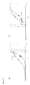
- the saturation relationship s ( ⁇ ) implies a strongly hysteretic behavior, represented by a main drying curve and main wetting curve, as shown in Figures 13 a) and b ).
- s min and s max denote the minimum (i.e., residual) and maximum saturation values, respectively, for a given material. If a particular node reverses from wetting to drying, the main drying curve is scaled by changing the maximum saturation value for that curve such that the reversal point falls on the resulting curve. Analogously, if the reversal is in the opposite direction, the main wetting curve is scaled by changing the minimum saturation value. An individual scanning curve is maintained for each node.
- the reversal point ⁇ rev is used to define a linear scaling according to Figure 13 .
- AGM - refers to the fluid-swellable solid material, e.g. including absorbent gelling material, as described herein above.
- AF- refers to airfelt material or any other non fluid-swellable component of the fluid-swellable solid material, e.g. glues, polymers, etc.
- FIG 2 is a schematic of the components of the virtual test environment 22.
- the virtual test environment may include the equations herein above
- the spatial domain of the absorbent (structure or region or layer thereof) 40 is specified and is divided into suitable volume elements, which together form what is commonly referred to as the mesh, further exemplified in Figure 10 and 11 .
- Each vertex of a mesh element is called node.
- the mesh can be coarse or fine, the choice of which requires consideration of the computing time for the virtual test environment 22 and the precision of results. A suitable coarseness or fineness can be determined by trial and error.
- Such mesh elements can be triangles and quadrilaterals in 2D, while in 3D they can be hexahedra (also known as hexes or hex elements), tetrahedra (tets), square pyramids (pyramids) and extruded triangles (wedges or triangular prisms).
- Representative initial conditions of the absorbent core or layer 42 are also specified.
- the initial conditions of the absorbent 42 can be the same throughout the entire absorbent 40 or vary spatially.
- Initial saturation can be assumed to be zero, which is representative of an absorbent region or layer free of fluid.
- the absorbent in the virtual test environment 22 can be assumed to have an initial saturation that is not zero.
- a non-zero initial saturation can be representative of an absorbent that has absorbed fluid even in ambient conditions.
- Ambient conditions are the conditions of the absorbent prior to exposure to an insult of fluid.
- Representative boundary conditions of the absorbent 44 are prescribed for the virtual test environment 22. Boundary conditions can be for instance a given flux or a given constant saturation.
- An example of a boundary condition may be determined by a standard acquisition test with four 75 ml gushes and 5 minutes between the gushes, or 1 single gush of 10ml. However any other test protocol can be herein described via properly formulating the boundary conditions.
- Representative physical properties of the absorbent 46 are including permeability, capillary pressure, swelling speed, maximum capacity, porosity, fluid-swellable composite material concentration.
- Representative absorbent-fluid interaction properties 48 for the absorbent are also specified and include parameters of capillary pressure as function of saturation, relative permeability as function of saturation; they include all the dependencies of permeability, capillary pressure, swelling speed, and porosity on AGM x-load.,
- Physical properties of the fluid 52 are also specified and include the fluid density, fluid viscosity.
- the equations describing the virtual test environment 22 can be solved using direct methods, iterative methods, or any other methods known to those skilled in the art.
- Physical properties of the fluid-swellable (composite) material (also referred to as absorbent) in the absorbent article are also specified for the virtual model of an absorbent article.
- the physical properties of the absorbents in the absorbent article can be obtained from direct measurements of the properties, indirect measurements, inverse modelling, curve-fitting, material property databases, estimation, and/or any other method known to those skilled in the art.
- the equations may for example be inputted into commercially available software.
- One example is to solve the equations herein, e.g. (E1), with general purpose solvers such as Fortran, gPROMS, or with commercial software, as for example Feflow, from Wasy GmbH, Walterdorfer Str. 105, 12526 Berlin Germany.
- the virtual model may also be performed iteratively by a software program developed in FORTRAN, C++, or similar programming language.
- solver conditions and convergence criteria are specified.
- the start time, end time, maximum time-step, and initial time-step are also specified and put into the data set.
- the gravitational acceleration constant, reference temperature, and reference pressure are also put into the solver data set.
- the matrix of equations describing the virtual model may need to be preconditioned so that a solution meeting the specified convergence criteria is obtained.
- Trial and error can be used to determine if preconditioning is required.
- convergence criteria and stability parameters are input to control the virtual test environment 22.
- the convergence criteria and stability parameters can be selected on a trial and error basis. As with most numerical solution approaches, there can be some trade-off between the criteria selected to control the virtual test environment 22 and the time required for solution and precision of results.
- Feflow When Feflow is executed, Feflow creates output files as specified by the output controls.
- the output controls specify which time-steps output files are to be generated and what information is to be reported with each output file.
- Output from the virtual test environment 22 can comprise fluid saturation as a function of time and position. For each time-step for which output data is generated, the saturation S, amount of liquid in fluid-swellable composite material m 2 , the capillary pressure for each cell can be reported.
- the virtual test environment 22 can be used to generate a virtual spatial map of saturation as a function of location as a function of time.
- the mesh can be uniform or non-uniform within a single layer structure, e.g. of said fluid-swellabel composite material.
- a mesh example is shown on Figures 10 and 11 .
- Figure 3 is a block diagram illustrating one example of a computer system 200 for operating the virtual test environment 22 and the virtual model of an absorbent article.
- the computer system 200 comprises a central processing unit 210, a graphical user interface 220 including a display communicatively coupled to the central processing unit 210, and a user interface selection device 230 communicatively coupled to the central processing unit 210.
- the user interface selection device 230 can be used to input data and information into the central processing unit 210.
- the central processing unit 210 can include or has access to memory or data storage units, e.g., hard drive(s), compact disk(s), tape drive(s), and similar memory or data storage units for storing various data and inputs which can be accessed and used in operating the virtual test environment 22 and the virtual model of an absorbent article.
- Central processing unit 210 can be part of a SUN workstation running a UNIX® operating system, part of a personal computer using INTEL® PC architecture and running a MICROSOFT WINDOWS® operating system, or part of another similarly capable computer architecture and accompanying operating system.
- the above described method and system can be used to calculate features correlated with the performance of an absorbent article, or said fluid-swellable composite material herein, that may comprise one or more fluid-swellable solid materials; one or more non-swellable materials; one or more layers; different geometries, including flat and curved and/ or two- or three dimensional geometries, symmetrical or non-symmetrical etc.
- the swelling behaviour can be determined and exemplified in such a manner, but also other features such a level of saturation of the void space(s), for one or more locations of the article or of the fluid-swellable composite material thereof; or for example the absorption/ liquid present in the fluid-swellable solid material of the article; or for example values of capillary pressure, permeability, porosity at a certain location of the article or of the fluid-swellable composite material, at a given time; or to determine the dimensions at a given location, e.g. including thickness, of the absorbent article, or structure or fluid-swellable composite material thereof, at a function of time or at a given time.
- the fluid-swellable composite comprises in addition a non-swellable material that has a certain porosity and permeability, and a property of said non-swellable material is inputted into the virtual model herein, e.g. the porosity, permeability and/ or the capillary pressure, and typically the dimensions such a width, length, or surface areas, and thickness (calliper) (as further set out in co pending application US application 11/504993 .
- non-swellable materials may include acquisition materials, surge layers, cellulosic materials, nonwovens, as known in the art in absorbent structures.
- the model herein is useful to predict the performance of the absorbent article or a fluid-swellable composite material thereof, for example in the form of a (layered) structure, while only needing to obtain certain fluid-swellable composite material properties such as:
- Porosity of the fluid-swellable (composite) material can be obtained from the capillary pressure versus saturation function (or data), computed using mass/volume/density relationships, measured using a column test, determined from image interpretation, or any other method known to those skilled in the art.
- porosity data can be determined as function of fluid-swellable composite material load (different salt concentration would induce a different swelling extent). Data of porosity as function of fluid-swellable composite material x-load m 2 s may then be fitted with any convenient mathematical dependency.
- ⁇ max , ⁇ scale and ⁇ exp are fitting parameters, to be determined with fitting methods, known in the art.
- AGM speed rate constant and Maximum AGM x-load are properties dependent on the type of fluid-swellable (composite) material used, the external pressure, temperature, and the liquid type used.
- the method as described below in the "capillary pressure section” can be executed with air pressure equal to atmospheric pressure, where the absorbent material will be fully loaded.
- the recorded "uptake versus time” data is then used with equation (E34) and (E33), getting the unknown parameters AGM speed rate constant ( ⁇ ) and Maximum AGM x-load m max s
- permeability is a tensor, i.e. the components in the different directions, should be considered, as described in the model equations.
- K being the conductivity
- k being the permeability
- ⁇ being the density
- g being the gravitational acceleration
- ⁇ being the viscosity
- I being the unity vector, as described herein and/ or as defined in the first nomenclature list above.
- the saturated permeability k of an absorbent can be directly measured in the laboratory.
- the in-plane and thru-plane saturated permeability can be measured using any means known to those skilled in the art including, but not limited to, constant hydrostatic pressure head method, and constant volume flow rate method.
- the saturated absorbent can be subjected to a constant hydrostatic pressure head from a column of fluid about 1 to about 100 cm in height. The preferred column height range is from about 5 to about 50 cm.
- the material can be held in place solely by the hydrostatic pressure head of the fluid or with additional confining pressure.
- the mass flow rate of fluid through the absorbent layer or core is recorded for a set period of time.
- the mass flow rate is used to calculate the saturated permeability of the absorbent, knowing the area of the absorbent orthogonal to the direction of flow, the thickness of the absorbent in a direction in-plane with the direction of flow, and the change in total pressure head across the absorbent.
- k as function of x-load m 2 s can be obtained by modifying any of the methods above as follows.
- liquids with different salt concentrations e.g. ranging for instance from 0.5 to 25% of NaCl by weight, are used (a different salt concentration would induce a different swelling extent) and then permeability at a specific x-load m 2 s can be measured.
- the specific x-load m 2 s corresponding to a certain salt concentration can be measured as in the porosity method described herein.
- the relative permeability is described through a power model, where the coefficient ⁇ can be estimated based on the literature values or calculated with inverse fitting. A typical value for ⁇ ranges between 3 and 5. Alternatively, other models, such as the van Genuchten-Mualem model for relative permeability, can be used for this scope.
- Capillary pressure for a fluid swellable (composite) material is herein given as a complex function of fluid-swellable composite material x-load m 2 s and saturation s l e .
- Equation (E38) and (E39) can be determined from fitting experimental capillary pressure curves, including both uptake and retention curves, obtained at different m 2 s , different parameters will be determined for the uptake and retention branches of the hysteresis curves. (The parameters are as specific in the first nomenclature list above).
- Figure 5 represents a schematic of a typical method used to measure capillary pressure curves of porous media.
- the pre-saturated specimen is place on a microporous membrane which is itself supported by a rigid porous plate.
- the pre-saturated specimen may be obtained by any method, such as placing a dry sample onto the membrane and decreasing the chamber gas pressure to the atmospheric pressure, and allowing the liquid to enter into all the pores of the material.
- the gas pressure within the chamber is increased in steps, causing liquid to flow out of some of the pores, i.e. out of the largest pores first.
- the amount of liquid removed is monitored by the top-loading recording balance. In this way each level of applied pressure (which determines the largest effective pore size that remains filled) is related to an increment of liquid mass.
- the chamber is pressurized by means of a computer controlled, reversible, motor driven piston/ cylinder arrangement that can produce the required changes in pressure to cover a pore radius range from 1 to 1000 micron.
- fluid-swellable (composite) material itself that is pre-swollen to full load (e.g. by leaving the specimen under atmospheric pressure for at least 2 hours in the test liquid), by then increasing the outside air pressure and measuring the retention curve, and then decreasing this again to measure the uptake curve.
- fluid-swellable composite material can be swollen to different x-load with liquids having different salt concentration, as explained in the permeability section.
- Figure 5 shows typical capillary pressure curves as measured with the method above with the test equipment shown in Figure 4 .
- the capillary pressure for a specific liquid of known contact angle and surface tension may be obtained from the measured capillary pressure of a second liquid of known contact angle and surface tension.
- Viscosity can be determined with any viscosity method available in the art, e.g. ISO/TR 3666:1998 or DIN 53018-1:1976.
Landscapes
- Engineering & Computer Science (AREA)
- Physics & Mathematics (AREA)
- Theoretical Computer Science (AREA)
- Computer Hardware Design (AREA)
- Evolutionary Computation (AREA)
- Geometry (AREA)
- General Engineering & Computer Science (AREA)
- General Physics & Mathematics (AREA)
- Absorbent Articles And Supports Therefor (AREA)
Priority Applications (3)
| Application Number | Priority Date | Filing Date | Title |
|---|---|---|---|
| EP09153881A EP2224362A1 (fr) | 2009-02-27 | 2009-02-27 | Procédé d'évaluation de comportement d'absorption d'articles absorbants |
| PCT/US2010/024265 WO2010099001A1 (fr) | 2009-02-27 | 2010-02-16 | Procédé d'évaluation de comportement d'absorption d'articles absorbants |
| US12/660,446 US8498851B2 (en) | 2009-02-27 | 2010-02-26 | Method for evaluation of absorption behavior of absorbent articles |
Applications Claiming Priority (1)
| Application Number | Priority Date | Filing Date | Title |
|---|---|---|---|
| EP09153881A EP2224362A1 (fr) | 2009-02-27 | 2009-02-27 | Procédé d'évaluation de comportement d'absorption d'articles absorbants |
Publications (1)
| Publication Number | Publication Date |
|---|---|
| EP2224362A1 true EP2224362A1 (fr) | 2010-09-01 |
Family
ID=40679267
Family Applications (1)
| Application Number | Title | Priority Date | Filing Date |
|---|---|---|---|
| EP09153881A Withdrawn EP2224362A1 (fr) | 2009-02-27 | 2009-02-27 | Procédé d'évaluation de comportement d'absorption d'articles absorbants |
Country Status (3)
| Country | Link |
|---|---|
| US (1) | US8498851B2 (fr) |
| EP (1) | EP2224362A1 (fr) |
| WO (1) | WO2010099001A1 (fr) |
Cited By (4)
| Publication number | Priority date | Publication date | Assignee | Title |
|---|---|---|---|---|
| US7979256B2 (en) | 2007-01-30 | 2011-07-12 | The Procter & Gamble Company | Determining absorbent article effectiveness |
| US8737704B2 (en) | 2006-08-08 | 2014-05-27 | The Procter And Gamble Company | Methods for analyzing absorbent articles |
| US9244022B2 (en) | 2011-06-16 | 2016-01-26 | The Procter & Gamble Company | Mannequins for use in imaging and systems including the same |
| CN113155678A (zh) * | 2021-04-22 | 2021-07-23 | 浙江昱升个人护理用品有限公司 | 防溢乳垫吸收性能测试仪 |
Families Citing this family (6)
| Publication number | Priority date | Publication date | Assignee | Title |
|---|---|---|---|---|
| CA2954181C (fr) | 2014-07-03 | 2023-01-24 | Zohar Laufer | Systeme de suivi et de detection de proximite personnel |
| US11612278B2 (en) | 2019-01-02 | 2023-03-28 | Charles Agnew Osborne, Jr. | Power management system for dispensers |
| CN111690831B (zh) * | 2020-05-29 | 2022-05-24 | 江西理工大学 | 一种离子型稀土矿的注液工艺优化方法 |
| US12587274B2 (en) | 2023-03-28 | 2026-03-24 | Quantum Generative Materials Llc | Satellite optimization management system based on natural language input and artificial intelligence |
| US12368503B2 (en) | 2023-12-27 | 2025-07-22 | Quantum Generative Materials Llc | Intent-based satellite transmit management based on preexisting historical location and machine learning |
| US12603701B2 (en) | 2023-12-27 | 2026-04-14 | Quantum Generative Materials Llc | Distributed satellite constellation management and control system |
Citations (2)
| Publication number | Priority date | Publication date | Assignee | Title |
|---|---|---|---|---|
| US20050256686A1 (en) * | 2004-05-11 | 2005-11-17 | Kimberly-Clark Worldwide, Inc. | Method of evaluating the performance of a product using a virtual environment |
| US20080046202A1 (en) | 2006-08-16 | 2008-02-21 | The Procter & Gamble Company | Method for designing an absorbent article |
Family Cites Families (1)
| Publication number | Priority date | Publication date | Assignee | Title |
|---|---|---|---|---|
| US20070231901A1 (en) * | 2005-12-02 | 2007-10-04 | Shuichi Takayama | Microfluidic cell culture media |
-
2009
- 2009-02-27 EP EP09153881A patent/EP2224362A1/fr not_active Withdrawn
-
2010
- 2010-02-16 WO PCT/US2010/024265 patent/WO2010099001A1/fr not_active Ceased
- 2010-02-26 US US12/660,446 patent/US8498851B2/en not_active Expired - Fee Related
Patent Citations (2)
| Publication number | Priority date | Publication date | Assignee | Title |
|---|---|---|---|---|
| US20050256686A1 (en) * | 2004-05-11 | 2005-11-17 | Kimberly-Clark Worldwide, Inc. | Method of evaluating the performance of a product using a virtual environment |
| US20080046202A1 (en) | 2006-08-16 | 2008-02-21 | The Procter & Gamble Company | Method for designing an absorbent article |
Non-Patent Citations (6)
| Title |
|---|
| "Absorbent Technology", ELSEVIER, pages: 426 - 436 |
| BARRY J ET AL: "COMPUTATIONAL FLUID DYNAMICS MODELING OF FABRIC SYSTEMS FOR INTELLIGENT GARMENT DESIGN", MRS BULLETIN, PITTSBURGH, US, vol. 28, no. 8, 1 August 2003 (2003-08-01), pages 568 - 573, XP009052181 * |
| DE BOOR: "A practical guide to splines, Rev", 2001, SPRINGER |
| DIERSCH; PERROCHET: "On the primary variable switching techniques for simulating unsatured-saturated flows", ADV. WATER RESOUR., vol. 23, 1999, pages 271 - 301 |
| FREDRIC L. BUCHHOLZ: "Journal of Applied Polymer Science", vol. 102, 2006, DOW CHEMICAL COMPANY, article "Model of Liquid Permeability in Swollen Composites of Superabsorbent Polymer and Fiber", pages: 4075 - 4084 |
| MILLER; TYOMKIN: "Liquid Porosimetry: New Methodology and Applications", JOURNAL OF COLLOID AND INTERFACE SCIENCE, vol. 162, 1994, pages 163 - 170 |
Cited By (5)
| Publication number | Priority date | Publication date | Assignee | Title |
|---|---|---|---|---|
| US8737704B2 (en) | 2006-08-08 | 2014-05-27 | The Procter And Gamble Company | Methods for analyzing absorbent articles |
| US9224032B2 (en) | 2006-08-08 | 2015-12-29 | The Procter & Gamble Company | Methods for analyzing absorbent articles |
| US7979256B2 (en) | 2007-01-30 | 2011-07-12 | The Procter & Gamble Company | Determining absorbent article effectiveness |
| US9244022B2 (en) | 2011-06-16 | 2016-01-26 | The Procter & Gamble Company | Mannequins for use in imaging and systems including the same |
| CN113155678A (zh) * | 2021-04-22 | 2021-07-23 | 浙江昱升个人护理用品有限公司 | 防溢乳垫吸收性能测试仪 |
Also Published As
| Publication number | Publication date |
|---|---|
| US8498851B2 (en) | 2013-07-30 |
| US20110138894A1 (en) | 2011-06-16 |
| WO2010099001A1 (fr) | 2010-09-02 |
Similar Documents
| Publication | Publication Date | Title |
|---|---|---|
| US8498851B2 (en) | Method for evaluation of absorption behavior of absorbent articles | |
| US7869964B2 (en) | Method for evaluation of absorption behavior of absorbent articles | |
| WO2008020411A2 (fr) | Méthode de conception d'un article absorbant | |
| CN101595483B (zh) | 确定吸收制品功效 | |
| Ehlers et al. | A linear viscoelastic biphasic model for soft tissues based on the theory of porous media | |
| US8386219B2 (en) | Computer based models for absorbent articles | |
| Masoodi et al. | Numerical simulation of liquid absorption in paper‐like swelling porous media | |
| EP2054825A2 (fr) | Procédé pour mesurer les propriétés de transport de fluide partiellement saturé d'un absorbant | |
| US20130018348A1 (en) | Absorbent core | |
| CN103002847B (zh) | 吸收芯 | |
| Wein et al. | Topology optimization of unsaturated flows in multi-material porous media: Application to a simple diaper model | |
| Mirnyy et al. | Wicking in absorbent swelling porous materials | |
| US20140005983A1 (en) | Microscale modeling of porous media flow | |
| US9092585B2 (en) | Computer based models for absorbent articles | |
| US20140149097A1 (en) | Method to determine lotion effectiveness of a virtual absorbent article | |
| Santagata et al. | Modelling and experimental characterization of unsaturated flow in absorbent and swelling porous media: material characterization | |
| US8468000B1 (en) | Computer based models for absorbent articles | |
| US9292636B2 (en) | Method for modeling an exudate on a substrate | |
| Πουρνάρας et al. | Permeability of fluid absorbing media | |
| Gaballa | Nonlinear multiphasic mechanics of soft tissue using finite element methods | |
| Brandão | Modeling of water up-take in superabsorbent systems |
Legal Events
| Date | Code | Title | Description |
|---|---|---|---|
| PUAI | Public reference made under article 153(3) epc to a published international application that has entered the european phase |
Free format text: ORIGINAL CODE: 0009012 |
|
| AK | Designated contracting states |
Kind code of ref document: A1 Designated state(s): AT BE BG CH CY CZ DE DK EE ES FI FR GB GR HR HU IE IS IT LI LT LU LV MC MK MT NL NO PL PT RO SE SI SK TR |
|
| AX | Request for extension of the european patent |
Extension state: AL BA RS |
|
| 17P | Request for examination filed |
Effective date: 20110202 |
|
| 17Q | First examination report despatched |
Effective date: 20110222 |
|
| AKX | Designation fees paid |
Designated state(s): AT BE BG CH CY CZ DE DK EE ES FI FR GB GR HR HU IE IS IT LI LT LU LV MC MK MT NL NO PL PT RO SE SI SK TR |
|
| RIN1 | Information on inventor provided before grant (corrected) |
Inventor name: MYRNYY, VOLODYMYR Inventor name: DIERSCH, HANS-JOERG Inventor name: BERUDA, HOLGER Inventor name: ROSATI, RODRIGO Inventor name: CLAUSNITZER, VOLKER Inventor name: SCHMIDT, MATTIAS Inventor name: EHRNSPERGER, BRUNO JOHANNES Inventor name: VIRGILIO, RAFFAELE |
|
| STAA | Information on the status of an ep patent application or granted ep patent |
Free format text: STATUS: THE APPLICATION IS DEEMED TO BE WITHDRAWN |
|
| 18D | Application deemed to be withdrawn |
Effective date: 20140902 |