EP2224480A1 - Verbesserte Struktur eines Kühlkörpers - Google Patents
Verbesserte Struktur eines Kühlkörpers Download PDFInfo
- Publication number
- EP2224480A1 EP2224480A1 EP09153656A EP09153656A EP2224480A1 EP 2224480 A1 EP2224480 A1 EP 2224480A1 EP 09153656 A EP09153656 A EP 09153656A EP 09153656 A EP09153656 A EP 09153656A EP 2224480 A1 EP2224480 A1 EP 2224480A1
- Authority
- EP
- European Patent Office
- Prior art keywords
- radiator
- area
- heat
- dissipating
- chips
- Prior art date
- Legal status (The legal status is an assumption and is not a legal conclusion. Google has not performed a legal analysis and makes no representation as to the accuracy of the status listed.)
- Withdrawn
Links
- 239000000853 adhesive Substances 0.000 claims description 3
- 230000001070 adhesive effect Effects 0.000 claims description 3
- 230000000694 effects Effects 0.000 claims description 3
- 125000006850 spacer group Chemical group 0.000 description 10
- 238000000034 method Methods 0.000 description 2
- 241001391944 Commicarpus scandens Species 0.000 description 1
- XAGFODPZIPBFFR-UHFFFAOYSA-N aluminium Chemical compound [Al] XAGFODPZIPBFFR-UHFFFAOYSA-N 0.000 description 1
- 229910052782 aluminium Inorganic materials 0.000 description 1
- 230000002860 competitive effect Effects 0.000 description 1
- 238000002844 melting Methods 0.000 description 1
- 230000008018 melting Effects 0.000 description 1
- 230000000149 penetrating effect Effects 0.000 description 1
Images




Classifications
-
- H—ELECTRICITY
- H10—SEMICONDUCTOR DEVICES; ELECTRIC SOLID-STATE DEVICES NOT OTHERWISE PROVIDED FOR
- H10H—INORGANIC LIGHT-EMITTING SEMICONDUCTOR DEVICES HAVING POTENTIAL BARRIERS
- H10H20/00—Individual inorganic light-emitting semiconductor devices having potential barriers, e.g. light-emitting diodes [LED]
- H10H20/80—Constructional details
- H10H20/85—Packages
- H10H20/858—Means for heat extraction or cooling
- H10H20/8586—Means for heat extraction or cooling comprising fluids, e.g. heat-pipes
Definitions
- the present invention is related with the improved structure of LED radiator, especially for a radiator comprises with a better heat-dissipating plate bended through the machine as plurality of continuously arranged bottom area, side areas and top area. Because of the fast continuously caulking method for forming the radiator, it speeds the production, saves the time for dismantling and lowers the cost. It is very competitive and has economical efficiency.
- the radiator comprises each heat-dissipating chip dismantled one after one by hand.
- Each top end of the heat-dissipating chip has a top spacer and the bottom end of the heat-dissipating chip has a bottom spacer.
- a through hole is set on the corner between the top spacer and the heat-dissipating chip and between the bottom spacer and the heat-dissipating chip.
- the present invention is to improve the shortcomings of the prior invention for composing each heat-dissipating chip one after one.
- the present invention relates to a radiator comprising with a better heat-dissipating plate bended through machine as plurality of continuously arranged bottom area, side areas and top area.
- the length of the top area and the bottom area is the same.
- the top and the bottom areas are respectively vertical with the side area.
- the length of each side area is longer than each top and bottom area.
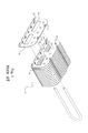
- the improved structure of the LED radiator comprises a better heat-dissipating plate (2) .
- a radiator (3) bended through machine has plurality of bottom area (21), side area (22), top area (23) and side area (22) which arranged continuously in upwardly opening order.
- the length of the top area (23) and the bottom area (21) on the radiator (3) is the same.
- the top area (23) and the bottom area (21) are respectively vertical with the side area (22), therefore, there is a space between top and the bottom as shown in Figs. 4 and 5 .
- the length of each side area (22) is the same and is longer than the length of the top area (23) and the bottom area (21).
- the radiator (3) can be adhesive with the top radiator (40) and the bottom radiator (41) to form a two-piece radiator (4) which has the same size as the radiator (3) shown in Fig. 4 .
- the radiator (5) comprises a bottom plate (52) and two-piece heat-dissipating chips (50) or plurality of heat-dissipating chips (51).
- the two-piece heat-dissipating chips (50) and the plurality of heat-dissipating chips (51) are formed through the machine, the two-piece heat-dissipating chips (50) has a bottom area (21) and two side areas (22) vertical with the bottom area (21), and the plurality of heat-dissipating chips (51) has more than two bottom areas (21) and more than two side areas (22).
- a bottom plate (52) in proper size can be fixed with more two-piece heat-dissipating chips (50) or plurality of heat-dissipating chips (51) thereon to form a radiator (5).
- fastened members (53) are set upwardly on the surface of the bottom plate (52).
- the fastened members (53) can be bended on the bottom area (21) between two side areas (22) to fix the two-piece heat-dissipating chips (50) or plurality of heat-dissipating chips (51).
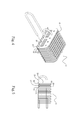
- the radiator (3) can be designed as a long-shaped radiator (6).
- the way to produce the long-shaped radiator (6) and the radiator (3) is the same, but the shape and the size are different.
- Move the long-shaped radiator (6) shown in Fig. 10 clockwise or counterclockwise to an angle of ninety degree, we will see the long-shaped radiator (6) shown in Fig. 11 is the same as the radiator (3) shown in Fig. 4 .
- the difference is where the bottom area (21) and the top area (23) are in lengthwise position and the side areas (22) are in sidelong position.
- the bottom of the radiator (3) can be designed as an arc and can be fixed with the curved heat-dissipating pipe (7). Therefore, the side areas (22) will spread radially to larger the space of each side area (22) and to increase the heat dissipating effect.
Landscapes
- Cooling Or The Like Of Semiconductors Or Solid State Devices (AREA)
Priority Applications (1)
| Application Number | Priority Date | Filing Date | Title |
|---|---|---|---|
| EP09153656A EP2224480A1 (de) | 2009-02-25 | 2009-02-25 | Verbesserte Struktur eines Kühlkörpers |
Applications Claiming Priority (1)
| Application Number | Priority Date | Filing Date | Title |
|---|---|---|---|
| EP09153656A EP2224480A1 (de) | 2009-02-25 | 2009-02-25 | Verbesserte Struktur eines Kühlkörpers |
Publications (1)
| Publication Number | Publication Date |
|---|---|
| EP2224480A1 true EP2224480A1 (de) | 2010-09-01 |
Family
ID=40983451
Family Applications (1)
| Application Number | Title | Priority Date | Filing Date |
|---|---|---|---|
| EP09153656A Withdrawn EP2224480A1 (de) | 2009-02-25 | 2009-02-25 | Verbesserte Struktur eines Kühlkörpers |
Country Status (1)
| Country | Link |
|---|---|
| EP (1) | EP2224480A1 (de) |
Citations (7)
| Publication number | Priority date | Publication date | Assignee | Title |
|---|---|---|---|---|
| EP0706212A2 (de) * | 1994-10-03 | 1996-04-10 | Sumitomo Chemical Company, Limited | Kühlrippenanordnung für ein LSI-Gehäuse |
| US6199624B1 (en) * | 1999-04-30 | 2001-03-13 | Molex Incorporated | Folded fin heat sink and a heat exchanger employing the heat sink |
| US6230789B1 (en) * | 1998-07-08 | 2001-05-15 | Foxconn Precision Componment Co., Ltd | Heat dissipating device and method making the same |
| US20020121365A1 (en) * | 2001-03-05 | 2002-09-05 | Kozyra Kazimierz L. | Radial folded fin heat sink |
| US20030048608A1 (en) * | 2001-09-10 | 2003-03-13 | Intel Corporation | Radial folded fin heat sinks and methods of making and using same |
| US6681847B1 (en) * | 2003-02-20 | 2004-01-27 | Advanced Thermal Technologies | Radiator fin formed by sintering operation |
| DE202004002339U1 (de) * | 2004-01-30 | 2004-04-15 | Datech Technology Co., Ltd., Hsin-Chuang | Kühlvorrichtung für integrierte Schaltkreise |
-
2009
- 2009-02-25 EP EP09153656A patent/EP2224480A1/de not_active Withdrawn
Patent Citations (7)
| Publication number | Priority date | Publication date | Assignee | Title |
|---|---|---|---|---|
| EP0706212A2 (de) * | 1994-10-03 | 1996-04-10 | Sumitomo Chemical Company, Limited | Kühlrippenanordnung für ein LSI-Gehäuse |
| US6230789B1 (en) * | 1998-07-08 | 2001-05-15 | Foxconn Precision Componment Co., Ltd | Heat dissipating device and method making the same |
| US6199624B1 (en) * | 1999-04-30 | 2001-03-13 | Molex Incorporated | Folded fin heat sink and a heat exchanger employing the heat sink |
| US20020121365A1 (en) * | 2001-03-05 | 2002-09-05 | Kozyra Kazimierz L. | Radial folded fin heat sink |
| US20030048608A1 (en) * | 2001-09-10 | 2003-03-13 | Intel Corporation | Radial folded fin heat sinks and methods of making and using same |
| US6681847B1 (en) * | 2003-02-20 | 2004-01-27 | Advanced Thermal Technologies | Radiator fin formed by sintering operation |
| DE202004002339U1 (de) * | 2004-01-30 | 2004-04-15 | Datech Technology Co., Ltd., Hsin-Chuang | Kühlvorrichtung für integrierte Schaltkreise |
Non-Patent Citations (1)
| Title |
|---|
| "HEAT TRANSFER STRUCTURE FOR SEMIRIGIDLY MOUNTED, SOLDER BALL-CONNECTED, IC CHIP", IBM TECHNICAL DISCLOSURE BULLETIN, IBM CORP. NEW YORK, US, vol. 32, no. 9B, 1 February 1990 (1990-02-01), pages 408/409, XP000082396, ISSN: 0018-8689 * |
Similar Documents
| Publication | Publication Date | Title |
|---|---|---|
| US20100218915A1 (en) | Structure of LED Radiator | |
| ES2736282T3 (es) | Unidad de visualización de pantalla LED y método de producción para la misma | |
| US20150122465A1 (en) | Heat sink device | |
| JP2016110076A5 (de) | ||
| WO2016025054A3 (en) | Engine components with impingement cooling features | |
| US20120199336A1 (en) | Heat sink with columnar heat dissipating structure | |
| US20180077817A1 (en) | Heat sink for head up display | |
| US20120251780A1 (en) | Building board | |
| RU2016137144A (ru) | Компоновка кинозалов в многозальных кинотеатрах и кинозал для многоэкранного кинотеатра | |
| JP2013254772A (ja) | ヒートシンク及びヒートシンク製造方法 | |
| US20030213582A1 (en) | Radiator with heat dissipation pieces connected in series | |
| JP2018025373A (ja) | 冷蔵庫用熱交換器及び冷蔵庫 | |
| JP6054423B2 (ja) | 流路部材およびこれを用いた熱交換器ならびに半導体装置 | |
| US20170260984A1 (en) | Fan blade with improved structure | |
| US20090183863A1 (en) | Connecting Structure for Connecting Heat Radiation Fins | |
| EP2224480A1 (de) | Verbesserte Struktur eines Kühlkörpers | |
| JP3171782U (ja) | 放熱を増強するフィン式放熱器 | |
| EP3131154A3 (de) | Kühlrippe, kühlmodul mit der kühlrippe und batteriemodul damit | |
| WO2010121428A1 (en) | Method of manufacturing heatsink with angled fins | |
| JP3181237U (ja) | Ledランプ | |
| JP3170440U (ja) | 鍛造品 | |
| JP2014126258A5 (de) | ||
| KR20120052509A (ko) | 히트싱크의 방열핀 | |
| CN203980207U (zh) | 一种散热器及具有该散热器的led灯具 | |
| KR200351757Y1 (ko) | 히트싱크 |
Legal Events
| Date | Code | Title | Description |
|---|---|---|---|
| PUAI | Public reference made under article 153(3) epc to a published international application that has entered the european phase |
Free format text: ORIGINAL CODE: 0009012 |
|
| AK | Designated contracting states |
Kind code of ref document: A1 Designated state(s): AT BE BG CH CY CZ DE DK EE ES FI FR GB GR HR HU IE IS IT LI LT LU LV MC MK MT NL NO PL PT RO SE SI SK TR |
|
| AX | Request for extension of the european patent |
Extension state: AL BA RS |
|
| 17P | Request for examination filed |
Effective date: 20110225 |
|
| 17Q | First examination report despatched |
Effective date: 20110406 |
|
| AKX | Designation fees paid |
Designated state(s): AT BE BG CH CY CZ DE DK EE ES FI FR GB GR HR HU IE IS IT LI LT LU LV MC MK MT NL NO PL PT RO SE SI SK TR |
|
| STAA | Information on the status of an ep patent application or granted ep patent |
Free format text: STATUS: THE APPLICATION IS DEEMED TO BE WITHDRAWN |
|
| 18D | Application deemed to be withdrawn |
Effective date: 20130903 |