EP2224576A2 - Stator pour un moteur à courant continu commuté électroniquement - Google Patents
Stator pour un moteur à courant continu commuté électroniquement Download PDFInfo
- Publication number
- EP2224576A2 EP2224576A2 EP09015223A EP09015223A EP2224576A2 EP 2224576 A2 EP2224576 A2 EP 2224576A2 EP 09015223 A EP09015223 A EP 09015223A EP 09015223 A EP09015223 A EP 09015223A EP 2224576 A2 EP2224576 A2 EP 2224576A2
- Authority
- EP
- European Patent Office
- Prior art keywords
- stator
- clamping ring
- stator according
- ring
- poles
- Prior art date
- Legal status (The legal status is an assumption and is not a legal conclusion. Google has not performed a legal analysis and makes no representation as to the accuracy of the status listed.)
- Granted
Links
Images


Classifications
-
- H—ELECTRICITY
- H02—GENERATION; CONVERSION OR DISTRIBUTION OF ELECTRIC POWER
- H02K—DYNAMO-ELECTRIC MACHINES
- H02K1/00—Details of the magnetic circuit
- H02K1/06—Details of the magnetic circuit characterised by the shape, form or construction
- H02K1/12—Stationary parts of the magnetic circuit
- H02K1/14—Stator cores with salient poles
- H02K1/146—Stator cores with salient poles consisting of a generally annular yoke with salient poles
- H02K1/148—Sectional cores
-
- H—ELECTRICITY
- H02—GENERATION; CONVERSION OR DISTRIBUTION OF ELECTRIC POWER
- H02K—DYNAMO-ELECTRIC MACHINES
- H02K1/00—Details of the magnetic circuit
- H02K1/06—Details of the magnetic circuit characterised by the shape, form or construction
- H02K1/12—Stationary parts of the magnetic circuit
- H02K1/18—Means for mounting or fastening magnetic stationary parts on to, or to, the stator structures
-
- H—ELECTRICITY
- H02—GENERATION; CONVERSION OR DISTRIBUTION OF ELECTRIC POWER
- H02K—DYNAMO-ELECTRIC MACHINES
- H02K15/00—Processes or apparatus specially adapted for manufacturing, assembling, maintaining or repairing of dynamo-electric machines
- H02K15/02—Processes or apparatus specially adapted for manufacturing, assembling, maintaining or repairing of dynamo-electric machines of stator or rotor bodies
- H02K15/028—Fastening stator or rotor bodies to casings, supports, shafts or hubs
-
- H—ELECTRICITY
- H02—GENERATION; CONVERSION OR DISTRIBUTION OF ELECTRIC POWER
- H02K—DYNAMO-ELECTRIC MACHINES
- H02K3/00—Details of windings
- H02K3/04—Windings characterised by the conductor shape, form or construction, e.g. with bar conductors
- H02K3/28—Layout of windings or of connections between windings
Definitions
- the invention relates to a stator (10) for an electronically commutated DC motor, having a plurality of stator poles (1) designed as individual parts, consisting of a pole core (25), pole shoes (26) and return sections (27), the return circuit sections (27).
- the stator poles (1) have interlocking profiles on which they abut one another so that they form a hollow cylindrical return (35) with each other, wherein the pole cores (25) radially inwardly connect to the return sections (27) that the individual stator poles (1 ) are each provided with an insulation and a winding and that the wound stator poles (1) are held together by a non-serving as a motor housing holding part.
- a generic stator is known in which two plastic holding parts are provided with axially projecting pins which engage in holes of the yoke portions of the stator poles and thereby connect them together. These plastic holding parts can only serve as adjustment means for the stator poles, but they do not sufficiently clamp together. For the bracing of the poles they must be pressed in a known manner in the motor housing. It is known by way of example to mount motor housings by shrinking onto the stator poles or to provide stator poles with yielding protrusions in order to allow them to be pressed into the motor housing. However, all these known methods can be carried out only with great difficulty.
- Object of the present invention is to present a stator for an electronically commutated DC motor, which can be easily and reliably mounted and facilitates the assembly of the stator in the motor housing.
- the characterizing part of claim 1 Since the holding part is a metallic clamping ring, which is placed under pretension around the entire circumference of the hollow cylindrical yoke around the stator poles can be easily clamped together, the clamping ring is needed neither as scrub gleichnoch as a motor housing element and therefore can for its primary task be designed and optimized. Since the stator does not necessarily have to be braced with the motor housing and the clamping ring and the motor housing does not have to serve as a return element, there is a greater freedom of design also in terms of the housing density and weight.
- Fig. 1 1 shows a stator pole 1, comprising a pole core 25, pole shoes 26, return sections 27, which have matching profiles in the form of a concave profile 28 and a convex profile 29, a trench-shaped recess 30 from which a projection 23 emerges.
- the projection 23 does not cover the entire length of the stator pole 1, but is arranged centrally and leaves at both ends a receiving space.
- the stator poles can be designed both as stanzmpêt parts and as powder-pressed parts.
- Fig. 2 shows an end cap 3, with a receiving space 24 for one-sided recording of the stator, in addition, the end cap 3 comprises receiving areas for a winding of a stator winding and slots 19 for fixing winding ends of the stator winding.
- Fig. 3 shows a further end cap 2, which is designed without slots, but otherwise as the end cap 3 is formed.
- Fig. 4 shows the end cap 2 from a different perspective.
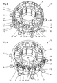
- Fig. 5 represents a stator 1 with mounted on the opposite end faces end caps 2, 3. End caps of this type are known and used in a variety of configurations.
- Fig. 6 shows for illustrative purposes a stator ring composed of nine stator poles without end caps and without winding.
- the stator is not present in any assembly step, because first the end caps and the winding are applied.
- Fig. 7 shows the stator Fig. 6 with mounted end caps 2 and 3.
- the winding is omitted for the sake of simplicity.
- the end caps do not extend into a radial region between the stator pole or pole shoe and a rotor, not shown here.
- All end caps 3 with slots 19 are arranged on the same side of the stator poles and all end caps 2 without slots on the opposite side.
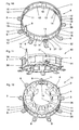
- Fig. 8 shows the arrangement according to Fig. 7 with additionally mounted clamping ring 4, which serves as a holding part for the stator poles.
- the clamping ring 4 is shown as a single part.
- the clamping ring is rolled in the example shown from a stamped sheet metal strip and mechanically connected at the ends.
- the connection point 13 is formed as caulked button.
- the clamping ring consists essentially of two annular regions 36, which are connected to each other via bridges 18.
- the bridges 18 are slightly deformed radially inwardly in their middle, so that a radial bias is given, which ensures a backlash-free connection between the clamping ring and the stator poles after assembly.
- connection between the two annular regions 36 is partially interrupted by recesses 37, so that webs 14 remain and H-shaped connecting regions remain between the annular regions 36.
- the annular regions 36 are deformed on the peripheral portions relative to the webs 14 radially inwardly.
- the axially inwardly deformed areas serve as Axialtechnischsstege 11 for axial fixation to the projections 23 of the stator poles 1.
- the clamping ring 4 is also integral with Anschraubgraphy 8, which are angled at right angles and extending radially outward.
- the Anschraubgraphy 8 are arranged in the peripheral portions in which bridges 18 or webs 14 between the annular regions 36 are present.
- the Anschraubgraphy 8 serve as a mounting option of the mounted stator in a motor housing.
- Next adjustment apertures 16 are provided parallel to the Anschraubösen 8, which are necessary for a precise position assignment of the stator in the motor housing.
- the clamping ring 4 comprises a star point terminal 9 which protrudes axially.
- the clamping ring can thus serve as an additional function as an electrical star point terminal 9 for the stator winding.
- Fig. 9 shows the arrangement according to Fig. 8 with additionally mounted insulating ring 5, which is pushed over the clamping ring 4 and fixed thereto.
- the insulating ring 5 is shown as a single part.
- the insulating ring has at a first axial end on its inner circumference on a reduced diameter portion which forms a stop ring 38.
- At the opposite axial end of the insulating ring is interrupted several times to achieve a radial compliance for its mounting on the stator.
- snap hook 17 are formed on the inner circumference.
- the area between the snap hook and the stop ring 38 is as Receiving space for the clamping ring 4 is provided.
- Justageroze 15 are mitgeformt that arephilgbar in the Justagesurchbrüche 16 of the clamping ring and thus allow accurate alignment.
- Justageroze 21 are mitgeformt on the axially opposite side, which serve to adjust a circuit board.
- the insulating ring 5 further has slots 20 for receiving the winding ends of the stator windings. To the inner regions of the slots 20 include receptacles 22 for insulation displacement contacts, which are mounted on the circuit board.
- the slots 20 are aligned with the slots 19 of the end caps 3 and are respectively mounted on the same side of the stator poles.
- Fig. 11 shows the simplified illustrated stator 10 without end caps and winding with mounted clamping ring 4.
- the Axialommesstege 11 take the space of recesses 30 and hold the clamping ring 4 axially fixed to the projections 23 at the stator poles.
- Fig. 12 shows a different perspective of the stator according to Fig. 11 with a pole omitted for ease of illustration. It can be clearly seen that the web 14, the circumferential contour of the clamping ring 4 is maintained while the Axialommesstege 11 are deformed inwards. In order to obtain this shape, the axial securing webs 11 must be stretched in relation to the original shape.
- Fig. 15 shows the stator 10, which is axially mounted in the motor housing 6 via screws 34.
- the stator is shown without Isolierring.
- connector pins 32 are mounted in a subsequent to the stator region of the motor housing 6 in a subsequent to the stator region of the motor housing 6 in a subsequent to the stator region of the motor housing 6 connector pins 32 are mounted.
- Fig. 16 shows the arrangement Fig. 15 with insulating ring 5, wherein insulation displacement contacts 31 are shown, which are actually not provided without circuit board in this mounting state.
- Fig. 17 shows the arrangement Fig. 16 with a printed circuit board 33 which are plugged onto the alignment pins 21 of the insulating ring 5 and interconnect the stator windings and connects to the connector pins 32.
- Fig. 18 shows the closed motor housing 6 with a housing cover. 7
Landscapes
- Engineering & Computer Science (AREA)
- Power Engineering (AREA)
- Manufacturing & Machinery (AREA)
- Insulation, Fastening Of Motor, Generator Windings (AREA)
Applications Claiming Priority (1)
| Application Number | Priority Date | Filing Date | Title |
|---|---|---|---|
| DE102009010782A DE102009010782A1 (de) | 2009-02-26 | 2009-02-26 | Stator für einen elektronisch kommutierten Gleichstrommotor |
Publications (3)
| Publication Number | Publication Date |
|---|---|
| EP2224576A2 true EP2224576A2 (fr) | 2010-09-01 |
| EP2224576A3 EP2224576A3 (fr) | 2016-09-07 |
| EP2224576B1 EP2224576B1 (fr) | 2020-04-01 |
Family
ID=42243025
Family Applications (1)
| Application Number | Title | Priority Date | Filing Date |
|---|---|---|---|
| EP09015223.2A Active EP2224576B1 (fr) | 2009-02-26 | 2009-12-09 | Stator pour un moteur à courant continu commuté électroniquement |
Country Status (3)
| Country | Link |
|---|---|
| US (1) | US8198780B2 (fr) |
| EP (1) | EP2224576B1 (fr) |
| DE (1) | DE102009010782A1 (fr) |
Cited By (1)
| Publication number | Priority date | Publication date | Assignee | Title |
|---|---|---|---|---|
| US11025128B2 (en) | 2016-11-16 | 2021-06-01 | Mitsubishi Electric Corporation | Protective cover for rotary electric machine |
Families Citing this family (8)
| Publication number | Priority date | Publication date | Assignee | Title |
|---|---|---|---|---|
| DE102010056120A1 (de) * | 2010-12-20 | 2012-07-05 | C. & E. Fein Gmbh | Verschaltungseinrichtung für einen Elektromotor |
| US9343930B2 (en) | 2012-05-25 | 2016-05-17 | Baldor Electric Company | Segmented stator assembly |
| DE102012020547A1 (de) * | 2012-10-19 | 2014-04-24 | Sew-Eurodrive Gmbh & Co Kg | Elektromotor mit Stator |
| JP6234457B2 (ja) * | 2013-07-19 | 2017-11-22 | 本田技研工業株式会社 | ステータ |
| US10177633B2 (en) | 2014-12-23 | 2019-01-08 | Abb Schweiz Ag | Multiphase fractional slot concentrated winding machine with end mounted detachable or integrated multiphase series converter circuit |
| EP3425770B1 (fr) * | 2016-02-29 | 2021-01-13 | Kabushiki Kaisha Yaskawa Denki | Machine électrique tournante et procédé de fabrication de machine électrique tournante |
| JP2020156147A (ja) * | 2019-03-18 | 2020-09-24 | 株式会社デンソー | ブラシレスモータ |
| JP6900988B2 (ja) * | 2019-10-15 | 2021-07-14 | ダイキン工業株式会社 | ロータリ圧縮機 |
Citations (1)
| Publication number | Priority date | Publication date | Assignee | Title |
|---|---|---|---|---|
| DE102005051506A1 (de) | 2005-10-26 | 2007-05-16 | Sew Eurodrive Gmbh & Co | Elektromotor und Verfahren zum Herstellen eines Elektromotors |
Family Cites Families (10)
| Publication number | Priority date | Publication date | Assignee | Title |
|---|---|---|---|---|
| US4425523A (en) * | 1982-06-04 | 1984-01-10 | Westinghouse Electric Corp. | Core spring support system for a dynamoelectric machine |
| US6941644B2 (en) * | 1999-09-27 | 2005-09-13 | Reliance Electric Technologies, Llc | Method for winding segments of a segmented wound member of an electromechanical device |
| DE10026003A1 (de) * | 2000-05-25 | 2001-12-06 | Bosch Gmbh Robert | Stator |
| JP3661589B2 (ja) * | 2000-11-21 | 2005-06-15 | 日産自動車株式会社 | モータまたは発電機 |
| WO2007107131A1 (fr) * | 2006-03-20 | 2007-09-27 | Temic Automotive Electric Motors Gmbh | Stator destiné à un moteur électrique et procédé de fabrication |
| JP2007259620A (ja) * | 2006-03-24 | 2007-10-04 | Matsushita Electric Ind Co Ltd | 固定子 |
| JP2008086172A (ja) * | 2006-09-28 | 2008-04-10 | Sumitomo Electric Ind Ltd | 焼嵌リングおよびモータのステータ |
| JP4807219B2 (ja) * | 2006-10-20 | 2011-11-02 | トヨタ自動車株式会社 | ステータコアおよび回転電機 |
| JP5172199B2 (ja) * | 2007-04-27 | 2013-03-27 | 住友電気工業株式会社 | ステータ |
| JP5354888B2 (ja) * | 2007-11-05 | 2013-11-27 | 株式会社ミツバ | ブラシレスモータ |
-
2009
- 2009-02-26 DE DE102009010782A patent/DE102009010782A1/de not_active Withdrawn
- 2009-12-09 EP EP09015223.2A patent/EP2224576B1/fr active Active
-
2010
- 2010-02-04 US US12/700,237 patent/US8198780B2/en active Active
Patent Citations (1)
| Publication number | Priority date | Publication date | Assignee | Title |
|---|---|---|---|---|
| DE102005051506A1 (de) | 2005-10-26 | 2007-05-16 | Sew Eurodrive Gmbh & Co | Elektromotor und Verfahren zum Herstellen eines Elektromotors |
Cited By (2)
| Publication number | Priority date | Publication date | Assignee | Title |
|---|---|---|---|---|
| US11025128B2 (en) | 2016-11-16 | 2021-06-01 | Mitsubishi Electric Corporation | Protective cover for rotary electric machine |
| EP3544155B1 (fr) * | 2016-11-16 | 2021-10-06 | Mitsubishi Electric Corporation | Capot de protection pour une machine dynamo-électrique |
Also Published As
| Publication number | Publication date |
|---|---|
| EP2224576B1 (fr) | 2020-04-01 |
| US8198780B2 (en) | 2012-06-12 |
| DE102009010782A1 (de) | 2010-09-09 |
| US20100213788A1 (en) | 2010-08-26 |
| EP2224576A3 (fr) | 2016-09-07 |
Similar Documents
| Publication | Publication Date | Title |
|---|---|---|
| EP2224576A2 (fr) | Stator pour un moteur à courant continu commuté électroniquement | |
| EP1748534B1 (fr) | Stator pour moteurs électriques comprenant un système d'interconnexion d'enroulement | |
| DE10152006B4 (de) | Stator für eine elektrische Maschine | |
| DE102015200093A1 (de) | Verschaltungsplatte eines Stators für eine elektrische Maschine und Verfahren zum Herstellen einer solchen | |
| DE102017222076B4 (de) | Elektromotor sowie Schalteinheit hierfür | |
| DE102018102976A1 (de) | Drahthalter | |
| EP2022157A1 (fr) | Procede de fabrication d'un stator et stator correspondant | |
| DE10115852A1 (de) | Elektrische Umlaufvorrichtung sowie zugehöriges Herstellungsverfahren | |
| DE10324666A1 (de) | Elektrische Maschine mit einem Ständer und einem Läufer | |
| DE4034277C2 (fr) | ||
| DE4241085A1 (fr) | ||
| DE102014220620A1 (de) | Anker, drehende elektrische Vorrichtung und Ankerherstellungsverfahren | |
| DE102010033699B4 (de) | Schaltkopf für Elektromotoren und Verfahren zum Verbinden eines Schaltkopfes mit den Anschlusslitzen einer Elektromotorwicklung | |
| DE20212273U1 (de) | Stator für einen Elektromotor | |
| DE3639004C2 (fr) | ||
| EP3192152B1 (fr) | Segment de bobinage pour l'enroulement de bobines statoriques d'un moteur électrique | |
| DE102012106224A1 (de) | Endkappenanordnung für einen Elektromotor | |
| DE102016211599A1 (de) | Segmentierter Stator und Verfahren zum Verschalten des Stators | |
| EP2226917A1 (fr) | Stator pour un moteur électrique, procédé de fabrication d'un tel stator et moteur électrique doté d'un tel stator | |
| DE102021214766A1 (de) | Stator für eine elektrische Maschine, eine elektrische Maschine und Verfahren zum Herstellen eines solchen Stators | |
| DE3538942A1 (de) | Feldstecker fuer einen elektromotor | |
| DE2064220A1 (de) | Anordnung zur Halterung und Fuhrung der Stromwenderbursten einer dynamoelektn sehen Maschine | |
| DE4339384A1 (de) | Schaltverbindung parallel gewickelter Schaltdrähte zu einem Sternpunkt einer Sternschaltung in Drehstrommotoren | |
| DE7720975U1 (de) | Spaltpolmotor | |
| DE2421480A1 (de) | Kommutator fuer elektrische maschinen |
Legal Events
| Date | Code | Title | Description |
|---|---|---|---|
| PUAI | Public reference made under article 153(3) epc to a published international application that has entered the european phase |
Free format text: ORIGINAL CODE: 0009012 |
|
| AK | Designated contracting states |
Kind code of ref document: A2 Designated state(s): AT BE BG CH CY CZ DE DK EE ES FI FR GB GR HR HU IE IS IT LI LT LU LV MC MK MT NL NO PL PT RO SE SI SK SM TR |
|
| AX | Request for extension of the european patent |
Extension state: AL BA RS |
|
| PUAL | Search report despatched |
Free format text: ORIGINAL CODE: 0009013 |
|
| AK | Designated contracting states |
Kind code of ref document: A3 Designated state(s): AT BE BG CH CY CZ DE DK EE ES FI FR GB GR HR HU IE IS IT LI LT LU LV MC MK MT NL NO PL PT RO SE SI SK SM TR |
|
| AX | Request for extension of the european patent |
Extension state: AL BA RS |
|
| RIC1 | Information provided on ipc code assigned before grant |
Ipc: H02K 3/28 20060101ALI20160803BHEP Ipc: H02K 1/14 20060101AFI20160803BHEP Ipc: H02K 15/02 20060101ALI20160803BHEP Ipc: H02K 1/18 20060101ALI20160803BHEP |
|
| STAA | Information on the status of an ep patent application or granted ep patent |
Free format text: STATUS: REQUEST FOR EXAMINATION WAS MADE |
|
| 17P | Request for examination filed |
Effective date: 20161213 |
|
| GRAP | Despatch of communication of intention to grant a patent |
Free format text: ORIGINAL CODE: EPIDOSNIGR1 |
|
| STAA | Information on the status of an ep patent application or granted ep patent |
Free format text: STATUS: GRANT OF PATENT IS INTENDED |
|
| INTG | Intention to grant announced |
Effective date: 20190920 |
|
| GRAS | Grant fee paid |
Free format text: ORIGINAL CODE: EPIDOSNIGR3 |
|
| GRAA | (expected) grant |
Free format text: ORIGINAL CODE: 0009210 |
|
| STAA | Information on the status of an ep patent application or granted ep patent |
Free format text: STATUS: THE PATENT HAS BEEN GRANTED |
|
| AK | Designated contracting states |
Kind code of ref document: B1 Designated state(s): AT BE BG CH CY CZ DE DK EE ES FI FR GB GR HR HU IE IS IT LI LT LU LV MC MK MT NL NO PL PT RO SE SI SK SM TR |
|
| REG | Reference to a national code |
Ref country code: GB Ref legal event code: FG4D Free format text: NOT ENGLISH |
|
| REG | Reference to a national code |
Ref country code: AT Ref legal event code: REF Ref document number: 1252628 Country of ref document: AT Kind code of ref document: T Effective date: 20200415 Ref country code: CH Ref legal event code: EP |
|
| REG | Reference to a national code |
Ref country code: DE Ref legal event code: R096 Ref document number: 502009016149 Country of ref document: DE |
|
| REG | Reference to a national code |
Ref country code: IE Ref legal event code: FG4D Free format text: LANGUAGE OF EP DOCUMENT: GERMAN |
|
| PG25 | Lapsed in a contracting state [announced via postgrant information from national office to epo] |
Ref country code: BG Free format text: LAPSE BECAUSE OF FAILURE TO SUBMIT A TRANSLATION OF THE DESCRIPTION OR TO PAY THE FEE WITHIN THE PRESCRIBED TIME-LIMIT Effective date: 20200701 |
|
| REG | Reference to a national code |
Ref country code: NL Ref legal event code: MP Effective date: 20200401 |
|
| REG | Reference to a national code |
Ref country code: LT Ref legal event code: MG4D |
|
| PG25 | Lapsed in a contracting state [announced via postgrant information from national office to epo] |
Ref country code: IS Free format text: LAPSE BECAUSE OF FAILURE TO SUBMIT A TRANSLATION OF THE DESCRIPTION OR TO PAY THE FEE WITHIN THE PRESCRIBED TIME-LIMIT Effective date: 20200801 Ref country code: SE Free format text: LAPSE BECAUSE OF FAILURE TO SUBMIT A TRANSLATION OF THE DESCRIPTION OR TO PAY THE FEE WITHIN THE PRESCRIBED TIME-LIMIT Effective date: 20200401 Ref country code: GR Free format text: LAPSE BECAUSE OF FAILURE TO SUBMIT A TRANSLATION OF THE DESCRIPTION OR TO PAY THE FEE WITHIN THE PRESCRIBED TIME-LIMIT Effective date: 20200702 Ref country code: NO Free format text: LAPSE BECAUSE OF FAILURE TO SUBMIT A TRANSLATION OF THE DESCRIPTION OR TO PAY THE FEE WITHIN THE PRESCRIBED TIME-LIMIT Effective date: 20200701 Ref country code: FI Free format text: LAPSE BECAUSE OF FAILURE TO SUBMIT A TRANSLATION OF THE DESCRIPTION OR TO PAY THE FEE WITHIN THE PRESCRIBED TIME-LIMIT Effective date: 20200401 Ref country code: NL Free format text: LAPSE BECAUSE OF FAILURE TO SUBMIT A TRANSLATION OF THE DESCRIPTION OR TO PAY THE FEE WITHIN THE PRESCRIBED TIME-LIMIT Effective date: 20200401 Ref country code: PT Free format text: LAPSE BECAUSE OF FAILURE TO SUBMIT A TRANSLATION OF THE DESCRIPTION OR TO PAY THE FEE WITHIN THE PRESCRIBED TIME-LIMIT Effective date: 20200817 Ref country code: LT Free format text: LAPSE BECAUSE OF FAILURE TO SUBMIT A TRANSLATION OF THE DESCRIPTION OR TO PAY THE FEE WITHIN THE PRESCRIBED TIME-LIMIT Effective date: 20200401 Ref country code: CZ Free format text: LAPSE BECAUSE OF FAILURE TO SUBMIT A TRANSLATION OF THE DESCRIPTION OR TO PAY THE FEE WITHIN THE PRESCRIBED TIME-LIMIT Effective date: 20200401 |
|
| PG25 | Lapsed in a contracting state [announced via postgrant information from national office to epo] |
Ref country code: LV Free format text: LAPSE BECAUSE OF FAILURE TO SUBMIT A TRANSLATION OF THE DESCRIPTION OR TO PAY THE FEE WITHIN THE PRESCRIBED TIME-LIMIT Effective date: 20200401 Ref country code: HR Free format text: LAPSE BECAUSE OF FAILURE TO SUBMIT A TRANSLATION OF THE DESCRIPTION OR TO PAY THE FEE WITHIN THE PRESCRIBED TIME-LIMIT Effective date: 20200401 |
|
| REG | Reference to a national code |
Ref country code: DE Ref legal event code: R097 Ref document number: 502009016149 Country of ref document: DE |
|
| PG25 | Lapsed in a contracting state [announced via postgrant information from national office to epo] |
Ref country code: DK Free format text: LAPSE BECAUSE OF FAILURE TO SUBMIT A TRANSLATION OF THE DESCRIPTION OR TO PAY THE FEE WITHIN THE PRESCRIBED TIME-LIMIT Effective date: 20200401 Ref country code: ES Free format text: LAPSE BECAUSE OF FAILURE TO SUBMIT A TRANSLATION OF THE DESCRIPTION OR TO PAY THE FEE WITHIN THE PRESCRIBED TIME-LIMIT Effective date: 20200401 Ref country code: RO Free format text: LAPSE BECAUSE OF FAILURE TO SUBMIT A TRANSLATION OF THE DESCRIPTION OR TO PAY THE FEE WITHIN THE PRESCRIBED TIME-LIMIT Effective date: 20200401 Ref country code: EE Free format text: LAPSE BECAUSE OF FAILURE TO SUBMIT A TRANSLATION OF THE DESCRIPTION OR TO PAY THE FEE WITHIN THE PRESCRIBED TIME-LIMIT Effective date: 20200401 Ref country code: IT Free format text: LAPSE BECAUSE OF FAILURE TO SUBMIT A TRANSLATION OF THE DESCRIPTION OR TO PAY THE FEE WITHIN THE PRESCRIBED TIME-LIMIT Effective date: 20200401 Ref country code: SM Free format text: LAPSE BECAUSE OF FAILURE TO SUBMIT A TRANSLATION OF THE DESCRIPTION OR TO PAY THE FEE WITHIN THE PRESCRIBED TIME-LIMIT Effective date: 20200401 |
|
| PLBE | No opposition filed within time limit |
Free format text: ORIGINAL CODE: 0009261 |
|
| STAA | Information on the status of an ep patent application or granted ep patent |
Free format text: STATUS: NO OPPOSITION FILED WITHIN TIME LIMIT |
|
| PG25 | Lapsed in a contracting state [announced via postgrant information from national office to epo] |
Ref country code: PL Free format text: LAPSE BECAUSE OF FAILURE TO SUBMIT A TRANSLATION OF THE DESCRIPTION OR TO PAY THE FEE WITHIN THE PRESCRIBED TIME-LIMIT Effective date: 20200401 Ref country code: SK Free format text: LAPSE BECAUSE OF FAILURE TO SUBMIT A TRANSLATION OF THE DESCRIPTION OR TO PAY THE FEE WITHIN THE PRESCRIBED TIME-LIMIT Effective date: 20200401 |
|
| 26N | No opposition filed |
Effective date: 20210112 |
|
| PG25 | Lapsed in a contracting state [announced via postgrant information from national office to epo] |
Ref country code: SI Free format text: LAPSE BECAUSE OF FAILURE TO SUBMIT A TRANSLATION OF THE DESCRIPTION OR TO PAY THE FEE WITHIN THE PRESCRIBED TIME-LIMIT Effective date: 20200401 |
|
| REG | Reference to a national code |
Ref country code: CH Ref legal event code: PL |
|
| PG25 | Lapsed in a contracting state [announced via postgrant information from national office to epo] |
Ref country code: MC Free format text: LAPSE BECAUSE OF FAILURE TO SUBMIT A TRANSLATION OF THE DESCRIPTION OR TO PAY THE FEE WITHIN THE PRESCRIBED TIME-LIMIT Effective date: 20200401 |
|
| REG | Reference to a national code |
Ref country code: BE Ref legal event code: MM Effective date: 20201231 |
|
| PG25 | Lapsed in a contracting state [announced via postgrant information from national office to epo] |
Ref country code: IE Free format text: LAPSE BECAUSE OF NON-PAYMENT OF DUE FEES Effective date: 20201209 Ref country code: LU Free format text: LAPSE BECAUSE OF NON-PAYMENT OF DUE FEES Effective date: 20201209 |
|
| PG25 | Lapsed in a contracting state [announced via postgrant information from national office to epo] |
Ref country code: LI Free format text: LAPSE BECAUSE OF NON-PAYMENT OF DUE FEES Effective date: 20201231 Ref country code: CH Free format text: LAPSE BECAUSE OF NON-PAYMENT OF DUE FEES Effective date: 20201231 |
|
| REG | Reference to a national code |
Ref country code: AT Ref legal event code: MM01 Ref document number: 1252628 Country of ref document: AT Kind code of ref document: T Effective date: 20201209 |
|
| PG25 | Lapsed in a contracting state [announced via postgrant information from national office to epo] |
Ref country code: AT Free format text: LAPSE BECAUSE OF NON-PAYMENT OF DUE FEES Effective date: 20201209 |
|
| PG25 | Lapsed in a contracting state [announced via postgrant information from national office to epo] |
Ref country code: TR Free format text: LAPSE BECAUSE OF FAILURE TO SUBMIT A TRANSLATION OF THE DESCRIPTION OR TO PAY THE FEE WITHIN THE PRESCRIBED TIME-LIMIT Effective date: 20200401 Ref country code: MT Free format text: LAPSE BECAUSE OF FAILURE TO SUBMIT A TRANSLATION OF THE DESCRIPTION OR TO PAY THE FEE WITHIN THE PRESCRIBED TIME-LIMIT Effective date: 20200401 Ref country code: CY Free format text: LAPSE BECAUSE OF FAILURE TO SUBMIT A TRANSLATION OF THE DESCRIPTION OR TO PAY THE FEE WITHIN THE PRESCRIBED TIME-LIMIT Effective date: 20200401 |
|
| PG25 | Lapsed in a contracting state [announced via postgrant information from national office to epo] |
Ref country code: MK Free format text: LAPSE BECAUSE OF FAILURE TO SUBMIT A TRANSLATION OF THE DESCRIPTION OR TO PAY THE FEE WITHIN THE PRESCRIBED TIME-LIMIT Effective date: 20200401 |
|
| PG25 | Lapsed in a contracting state [announced via postgrant information from national office to epo] |
Ref country code: BE Free format text: LAPSE BECAUSE OF NON-PAYMENT OF DUE FEES Effective date: 20201231 |
|
| P01 | Opt-out of the competence of the unified patent court (upc) registered |
Effective date: 20230920 |
|
| PGFP | Annual fee paid to national office [announced via postgrant information from national office to epo] |
Ref country code: DE Payment date: 20251218 Year of fee payment: 17 |
|
| PGFP | Annual fee paid to national office [announced via postgrant information from national office to epo] |
Ref country code: GB Payment date: 20251219 Year of fee payment: 17 |
|
| PGFP | Annual fee paid to national office [announced via postgrant information from national office to epo] |
Ref country code: FR Payment date: 20251208 Year of fee payment: 17 |