EP2224765A2 - Funkkommunikationssystem, Basisstationsvorrichtung, Gateway-Vorrichtung und Fernsteuerung - Google Patents
Funkkommunikationssystem, Basisstationsvorrichtung, Gateway-Vorrichtung und Fernsteuerung Download PDFInfo
- Publication number
- EP2224765A2 EP2224765A2 EP10001670A EP10001670A EP2224765A2 EP 2224765 A2 EP2224765 A2 EP 2224765A2 EP 10001670 A EP10001670 A EP 10001670A EP 10001670 A EP10001670 A EP 10001670A EP 2224765 A2 EP2224765 A2 EP 2224765A2
- Authority
- EP
- European Patent Office
- Prior art keywords
- intercell interference
- base station
- transmission method
- terminal
- base stations
- Prior art date
- Legal status (The legal status is an assumption and is not a legal conclusion. Google has not performed a legal analysis and makes no representation as to the accuracy of the status listed.)
- Withdrawn
Links
- 238000004891 communication Methods 0.000 title claims abstract description 92
- 230000009467 reduction Effects 0.000 claims abstract description 231
- 230000005540 biological transmission Effects 0.000 claims description 88
- 230000002093 peripheral effect Effects 0.000 claims description 53
- 238000000034 method Methods 0.000 claims description 50
- 230000004044 response Effects 0.000 claims description 41
- 238000012545 processing Methods 0.000 claims description 25
- 238000006243 chemical reaction Methods 0.000 claims description 4
- 238000011156 evaluation Methods 0.000 claims description 2
- 230000006870 function Effects 0.000 description 18
- 230000007704 transition Effects 0.000 description 15
- 230000006866 deterioration Effects 0.000 description 14
- 230000000694 effects Effects 0.000 description 10
- 238000001228 spectrum Methods 0.000 description 8
- 230000006872 improvement Effects 0.000 description 7
- 238000005259 measurement Methods 0.000 description 3
- 230000008901 benefit Effects 0.000 description 2
- 230000001419 dependent effect Effects 0.000 description 2
- 238000005516 engineering process Methods 0.000 description 2
- 238000012423 maintenance Methods 0.000 description 2
- 230000007246 mechanism Effects 0.000 description 2
- 238000011144 upstream manufacturing Methods 0.000 description 2
- 230000002776 aggregation Effects 0.000 description 1
- 238000004220 aggregation Methods 0.000 description 1
- 230000006399 behavior Effects 0.000 description 1
- 230000003247 decreasing effect Effects 0.000 description 1
- 239000006185 dispersion Substances 0.000 description 1
- 230000002452 interceptive effect Effects 0.000 description 1
- 238000012886 linear function Methods 0.000 description 1
- 230000007774 longterm Effects 0.000 description 1
- 230000008569 process Effects 0.000 description 1
- 238000012887 quadratic function Methods 0.000 description 1
- 238000012552 review Methods 0.000 description 1
- 230000008054 signal transmission Effects 0.000 description 1
- 238000012546 transfer Methods 0.000 description 1
Images











Classifications
-
- H—ELECTRICITY
- H04—ELECTRIC COMMUNICATION TECHNIQUE
- H04W—WIRELESS COMMUNICATION NETWORKS
- H04W72/00—Local resource management
- H04W72/50—Allocation or scheduling criteria for wireless resources
- H04W72/54—Allocation or scheduling criteria for wireless resources based on quality criteria
- H04W72/541—Allocation or scheduling criteria for wireless resources based on quality criteria using the level of interference
-
- H—ELECTRICITY
- H04—ELECTRIC COMMUNICATION TECHNIQUE
- H04W—WIRELESS COMMUNICATION NETWORKS
- H04W72/00—Local resource management
- H04W72/20—Control channels or signalling for resource management
- H04W72/27—Control channels or signalling for resource management between access points
-
- H—ELECTRICITY
- H04—ELECTRIC COMMUNICATION TECHNIQUE
- H04W—WIRELESS COMMUNICATION NETWORKS
- H04W72/00—Local resource management
- H04W72/20—Control channels or signalling for resource management
- H04W72/29—Control channels or signalling for resource management between an access point and the access point controlling device
-
- H—ELECTRICITY
- H04—ELECTRIC COMMUNICATION TECHNIQUE
- H04W—WIRELESS COMMUNICATION NETWORKS
- H04W72/00—Local resource management
- H04W72/50—Allocation or scheduling criteria for wireless resources
- H04W72/51—Allocation or scheduling criteria for wireless resources based on terminal or device properties
Definitions
- the present invention relates to a radio communications system in which plural base stations perform transmission/reception at the same frequency.
- intercell interference occurring to a radio communications system.
- FIG. 1 is view showing a radio communications system.
- a base station 101 transmits a radio signal to plural terminals 102, respectively, and receives a radio signal from the plural the terminals 102, respectively.
- a set of placements of the terminals 102, in which the base station 101 can communicate with the terminal 102 via a radio signal is a cell 103.
- the range of the cell 103 is dependent on propagation loss of a radio signal, interference between radio signals, that is, interference caused by signals to/from terminals belonging to other cells, respectively, and so forth.
- the range of the cell 103 is expressed by a circle for brevity. A portion where two circles overlap each other is susceptible to occurrence of the interference between radio signals. That is, it can be that the portion where two circles overlap each other is an area of intense intercell interference. Communication quality of terminals present in the vicinity of a boundary between the cells undergoes deterioration due to the intercell interference.
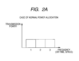
- FIG. 2A shows a transmission power spectrum in the case where reduction in intercell interference is not intended.
- the horizontal axis indicates fractional resource index, and the vertical axis indicates a transmission power for every fractional resource.
- time, frequency, or space can be considered as a candidate.
- a time frame can be cited.
- a transmission power may be defined for each of all time frames, however, as shown in an example of FIG. 2A , transmission powers corresponding to three time frames, respectively, may be first defined, and it may be defined that time frames whose number is divided by three, having a remainder equal in number, are treated as an identical fractional resource to be defined as corresponding to an identical transmission power.
- a sub-band that is a portion of a system-band can be cited.
- the system-band in whole is split into three portions as three sub-bands, thereby defining a transmission power for every sub-band.
- a directional beam can be cited.
- a cell formed by a base station is spatially split into three portions, thereby defining a transmission power as defined for every directional beam defined for every fractional space.
- a transmission power for every sector antenna is defined as shown in FIG. 2A .
- FIG. 2A shows an example where the transmission powers for the respective fractional resources are provided with a gradient in order to cause occurrence of the fractional resource low in the intercell interference.
- FIG. 2B shows a transmission power spectrum in the case where reduction in intercell interference is intended.
- FIG. 2B the vertical axis, and the horizontal axis each are the same in significance as those of FIG. 2A .
- FIG. 2B differs from FIG. 2A only in that a transmission power spectrum for every fractional resource varies from a base station to another.
- a fractional resource low in the intercell interference can be generated, and by allocating the fractional resource low in the intercell interference to a terminal at a cell boundary where intense intercell interference is received, it is possible to enhance the communication quality of the terminal at the cell boundary.
- a transmission power of a fractional resource 1 of a base station No. 1 is increased by reducing respective transmission powers of fractional resources 2, 3 of the base station No. 1.
- Transmission powers of respective fractional resources 1 of base stations Nos. 2, 3 are decreased under the same concept.
- the respective fractional resources 1 of the base stations Nos. 2, 3 have a transmission signal susceptible to have difficulty in reaching the neighborhood of a cell boundary
- the fractional resource 1 of the base station No. 1 has a transmission signal reaching the neighborhood of a cell with ease.
- a terminal in communication with the base station No. 1, and positioned in the neighborhood of the cell boundary will be able to communicate in an environment of low intercell interference if use is made of the fractional resource 1, thereby improving communication quality.
- a terminal in communication with the base station No. 2, and positioned in the neighborhood of the cell boundary a terminal in communication with the base station No.
- FIGs. 3A , 3B each show an example of the case where the number of the fractional resource axes is two.
- two fractional resources are selected out of three fractional resources including time, frequency, and space to be allocated to the respective axes.
- respective transmission powers of combinations of all the fractional resources are equal to each other, so that it is impossible to generate a fractional resource that is low in the intercell interference, however, in the case of an example shown in FIG. 3B , distribution of transmission powers between the fractional resources varies from one base station to another, so that it is possible to generate the fractional resource that is low in the intercell interference.
- the fractional resource of the terminal can be a combination of fractional resources where a transmission power from the base station No. 2 is weak, and a transmission power from the base station No. 1 is strong.
- three different way such as (1, B), (2, C) and (3, A) can be cited.
- the terminal since the communication quality of a radio channel changes every moment due to the effects of phasing, and shadowing, and the behavior of the fractional resource varies from one fractional resource to another, the terminal is able to make selective use of a fractional resource excellent in the communication quality among the combination (1, B), (2, C) and (3, A).
- an increase in the number of the fractional resource axes will contribute to an increase in selection diversity branches, and owing to advantageous effects thereof, the communication quality of the terminal can be enhanced.
- FIG. 4 there are shown results of analysis on the degree of improvement and deterioration in frequency utilization efficiency, due to execution of intercell interference reduction.
- the horizontal axis indicates received SNR at the terminal, and the vertical axis indicates received SIR at the terminal.
- This graph shows an improvement degree in the frequency utilization efficiency (bit/s/Hz), due to the execution of the intercell interference reduction.
- a minus improvement degree represents a deterioration degree.
- the number of base station is 2
- the number of terminals is 4
- the number of frequency sub-bands is 4
- a transmission power ratio among the four sub-bands is 2.5 : 2.5 : 2.5 : 2.5 when no intercell interference reduction is executed
- the transmission power ratio when the intercell interference reduction is executed is 1.0 : 7.0 : 1.0 : 1.0 among preferred base stations, and 1.0 : 1.0 : 7.0 : 1.0 among interference base stations, respectively.
- SIR is defined as a ratio of a signal reception power from a preferred base station of a sub-band having a transmission power equal to that of an interference base station to a signal reception power from the interference base station
- SNR is defined as a ratio of a noise power at a sub-band with its transmission power 1.0.
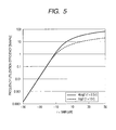
- FIG. 5 is a graph in which the horizontal axis indicates ⁇ , showing comparison results of frequency utilization efficiency.
- the invention provides a radio communications system in which a decision on whether or not intercell interference reduction is to be executed is made according to distribution of terminals, and in the case of execution, coordination among base stations is made before execution.
- Points for solving problems are the following three points:
- a radio communications system in which unit for checking terminal distribution on a base station-by-base station basis, unit for determining whether or not the intercell interference reduction is to be executed on the basis of results of the checking, and coordination unit for implementing the intercell interference reduction through cooperation among the base stations are installed a node closer to a core network than the base station, or the terminal is.
- the radio communications system according to the present invention has an advantageous effect in that reduction in the intercell interference leading to deterioration in communication quality can effectively executed.
- the reduction in the intercell interference can improve the communication quality of the terminal at the cell boundary, this can raise a possibility that the frequency utilization efficiency of the system as a whole undergoes deterioration.
- the reduction in the intercell interference is suitably executed according to distribution of terminals in such a way as to prevent deterioration in the frequency utilization efficiency of the system as a whole as much as possible, this will enable deterioration in the frequency utilization efficiency of the system as a whole to be prevented.
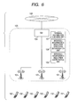
- FIG. 6 shows a system configuration according to the present invention.
- a radio access network is made up of one or plural base stations 101, one or plural terminals 102, in radio communication with one of the base stations 101, and a gateway 104, the radio access network incorporating a backhaul network 105 (excluding the terminals 102) in which a terminal distribution checking unit 107, an intercell interference reduction execution determination unit 108, and an intercell interference reduction coordination unit 109 are provided, this represents the best mode for carrying out the present invention.
- nodes where those three units are mounted respectively, three types of nodes including the base station 101, the gateway 104, and a remote controller for performing maintenance of the base station 101 can be cited.
- the gateway 104 is connected to a core network 106, but the core network 106 is unrelated to the invention.
- FIG. 7 shows a base station according to a first embodiment of the invention.
- This embodiment represents the case where the base station 101 is provided with the terminal distribution checking unit 107, the intercell interference reduction execution determination unit 108, and the intercell interference reduction coordination unit 109.
- reduction in the intercell interference can be achieved without the aid of the gateway 104, so that the present embodiment has an advantage in that the invention can be implemented without burdening the gateway 104 with a load.
- the present embodiment has a drawback in that there occurs an increase in process load of the base station 101, and an increase in communication using a control signal, for implementing intercell interference reduction through coordination between the base stations 101.
- the base station 101 is provided with a radio communication unit 201 for execution of radio communication with the terminal 102, the terminal distribution checking unit 107 for checking terminal distribution on the basis of a result of the radio communication with the terminal 102, the intercell interference reduction execution determination unit 108 for determining whether or not the intercell interference reduction is to be executed, the intercell interference reduction coordination unit 109 having a function for controlling whether or not the intercell interference reduction is to be executed by the base station 101 itself on the basis of results of determination by the intercell interference reduction execution determination unit 108 of the base station 101 itself, results of determination by the intercell interference reduction execution determination unit 108 of other base stations, and an execution state of the intercell interference reduction by the base station 101 itself, a function for exchanging control information on the intercell interference reduction execution with those other base stations, a function for controlling the execution state of the intercell interference reduction by the base station 101 itself, and a function for indicating whether or not the intercell interference reduction is executed to the radio communication unit 201 of the base station 101 itself, and a backhaul communication unit
- the radio communication unit 201 executes radio communication with the terminal 102 in accordance with a radio I/F (for example, Non-patent Document 3) of the radio communication protocol.
- a radio I/F for example, Non-patent Document 3
- This is realized with the use of a radio antenna for communication, an analog circuit for conversion of a carrier-band radio signal, and a baseband radio signal, and a logic circuit (ASIC, and FPGA) for taking out data of a received signal, and a control signal out of the baseband radio signal, or a program (DSP, and CPU).
- the control signal will be described in detail with reference to FIGs. 8A to 8D later on, and the radio communication unit 201 notifies the content of the control signal to the terminal distribution checking unit 107.
- the radio communication unit 201 holds a transmission power profile as shown in FIGs. 2A and 2B , and FIGs. 3A and 3B , executing switchover between FIGs. 2A and 2B , or switchover between FIGs. 3A
- the terminal distribution checking unit 107 can be realized by use a program (DSP, and CPU).
- the terminal distribution checking unit 107 generates a record which is to be referred to by the intercell interference reduction execution determination unit 108 on the basis of the relevant measurement result, and the control signal, outputted by the radio communication unit 201.
- the record will be described in detail with reference to FIGs. 10A to 10D later on.
- the intercell interference reduction execution determination unit 108 can be realized by use a program (DSP, and CPU).
- the intercell interference reduction execution determination unit 108 generates simple information which is to be referred to by the intercell interference reduction coordination unit 109, that is, information on whether or not the intercell interference reduction is to be executed through coordination between the base stations on the basis of the record generated by the terminal distribution checking unit 107.
- the intercell interference reduction coordination unit 109 has the following four functions, any of which can be realized by use a program (DSP, and CPU).
- the backhaul communication unit 202 communicates with those other base stations, and the gateway 104.
- the effect of the present invention remains unchanged regardless of the adoption of wire communication or radio communication.
- the backhaul communication unit 202 can be realized by use of network interface hardware in the case of wire communication, and by use of the same component as the radio communication unit 201 in the case of radio communication.
- FIG. 24 shows the configuration of the base station 101 in FIG. 7 .
- Each base station 101 is composed of a network interface device 301 which complies with the IEEE802.3 communication standard and which corresponds to the backhaul communications unit 202, a logic circuit 304 corresponding to the radio communications unit 201, an analog circuit 305, an antenna 306, a processor 302 to execute the terminal distribution checking unit 107, the intercell interference reduction execution unit 108, and the intercell interference reduction coordination unit 109, and a memory 303 which stores these executive programs.
- the logic circuit 304 performs baseband signal processing based on, for example, the LTE (long term evolution) communication standard.
- the analog circuit 305 makes conversion between baseband digital signals and radio frequency analog signal and thus includes a digital-analog converter, an analog-digital converter, an up-converter, down-converter, a power amplifier, a low-noise amplifier, and a duplexer
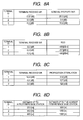
- FIGs. 8A to 8D each show an example of the control signal outputted by the radio communication unit 201, or the control signal whose information is processed.
- FIG. 8A shows the example in which measurement results of a received SIR (Signal to Interference Ratio), and a received SNR (Signal to Noise Ratio) of each of downstream signals at the respective terminals are mounted on an upstream signal before being fed back to the base station.
- the terminals each feed back an ID for uniquely fixing the identity of the terminal, and the received SNR as well as the received SIR, measured by a reference signal (a pilot signal) of the downstream signal, to the base station.
- a reference signal a pilot signal
- SIR can be estimated with relative ease by measuring a reference-signal power ratio between the base stations; however, SNR is difficult to be estimated because it is difficult to measure a noise power. Accordingly, use of RSSI (Received Signal Strength Indicator) instead of the received SNR is conceivable
- FIG. 8B shows the example in which RSSI is adopted.
- an operation at the terminal is substantially the same as that in the case of the example shown in FIG. 8A except that RSSI in place of the received SNR is adopted.
- RSSI represents a total receive power including the receive power of an interference signal
- RSSI has a feature that it nearly corresponds to SNR in an environment where SIR is high, and interference is less, but in an environment where SIR is low, and interference is strong, RSSI on a higher side is measured.
- FIG. 8C shows the example in which a propagation loss value in place of SNR, and RSSI is adopted.
- the propagation loss value can be calculated from the difference between a transmission power (dBm) and RSSI (dBm). If information on the transmission power is notified by the base station, the propagation loss value can be estimated by the terminal on the basis of the difference from RSSI.
- FIG. 8D shows the example in which a distance from a preferred base station transmitting a desired signal to a terminal, and a distance from an interference base station that is the nearest to a terminal among the base stations transmitting an interference signal to the terminal are used on the basis of position information on the base stations, and the terminal. More specifically, this example can be realized by a terminal measuring a terminal position with the use of GPS (Global Positioning System), HDP (Highly Detectable Pilot), and so forth, and feeding back the terminal position to a base station, whereupon the base station refers to a position information database of a neighborhood base station, thereby computing a distance between the terminal and the base station.
- GPS Global Positioning System
- HDP Highly Detectable Pilot
- the distance from the preferred base station to the terminal is related to SNR, and a relationship between two types of distances is related to SIR (the distance from the preferred base station is related to power of S, and the distance from the nearest interfering base station is related to power of I).
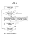
- FIG. 9 shows an example of the operation of the terminal distribution checking unit 107 according to the embodiment.
- the terminal distribution checking unit 107 execute a threshold determination against information shown in FIGs. 8A to 8D , respectively, thereby making a determination on whether or not the intercell interference reduction is to be executed on a terminal-by-terminal basis, and recording results of the determination.
- FIGs. 8A to 8D respectively, physical quantities (in FIG. 8A , terminal received sir) listed in the left-side column are designated ⁇ and physical quantities (in FIG. 8A , terminal received SNR) listed in the right -side column are designated ⁇ .
- a function with variables ⁇ , ⁇ is expressed as f ( ⁇ , ⁇ )
- a value of the function f ( ⁇ , ⁇ ) is less than the threshold ⁇ ⁇ it may be more than the threshold ⁇ depending on the definition of the function f ( ⁇ , ⁇ )
- an intercell interference reduction request flag is set to 1
- the intercell interference reduction request flag is set to 0
- Processing is repeated (S1001 to S1005, S1006) to give such determinations as above to all the terminals.
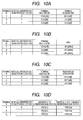
- FIGs. 10A to 10D each show an example of determination results of the intercell interference reduction request flag.
- f ⁇ , ⁇ ⁇ ⁇ 0.5 ⁇ ⁇ ⁇ ⁇
- FIG. 10A shows the determination results in the case where a rule according to the expression (1) is applied to a table of FIG. 8A , and the threshold ⁇ is 4.
- ⁇ is 15 while ⁇ is 20, and therefore, f ( ⁇ , ⁇ ) is found 5 by computation according to the expression (1), exceeding the threshold ⁇ , so that the terminal is determined as the terminal not requiring reduction in the intercell interference, whereupon the intercell interference reduction request flag is set to 0.
- ⁇ is 0 while ⁇ is 3, and therefore, f ( ⁇ , ⁇ ) is found - 1. 5 by computation according to the expression (1), falling short of the threshold ⁇ , so that the terminal is determined as the terminal requiring reduction in the intercell interference, whereupon the intercell interference reduction request flag is set to 1.
- the same can be of the terminal with the terminal ID "3".
- FIG. 10B shows the determination results in the case where a rule according to expression (2) is applied to a table of FIG. 8B , and the threshold ⁇ is 4.
- f ⁇ , ⁇ ⁇ ⁇ 0.5 ⁇ 100 + ⁇ ⁇ ⁇
- FIG. 10C shows the determination results in the case where a rule according to expression (3) is applied to a table of FIG. 8C , and the threshold ⁇ is 4.
- f ⁇ , ⁇ ⁇ ⁇ 0.5 ⁇ 130 ⁇ ⁇ ⁇ ⁇
- FIG. 10D shows the determination results in the case where a rule according to expression (4) is applied to a table of FIG. 8D , and the threshold ⁇ is 2000.
- f ⁇ , ⁇ ⁇ ⁇ 2 ⁇ ⁇ ⁇ ⁇ ⁇ ⁇ ⁇ ⁇
- ⁇ is 200 while ⁇ is 1800, and therefore, f ( ⁇ , ⁇ ) is found 3000 by computation according to the expression (4), exceeding the threshold ⁇ , so that the terminal is determined as the terminal not requiring reduction in the intercell interference, thereby setting the intercell interference reduction request flag to 0.
- ⁇ is 900 while ⁇ is 1000, and therefore, f ( ⁇ , ⁇ ) is found - 700 by computation according to the expression (4), falling short of the threshold ⁇ , so that the terminal is determined as the terminal requiring reduction in the intercell interference, thereby setting the intercell interference reduction request flag to 1.
- ⁇ is 900 while ⁇ is 1300, and therefore, f ( ⁇ , ⁇ ) is found - 100 by computation according to the expression (4), falling short of the threshold ⁇ , so that the terminal is determined as the terminal requiring reduction in the intercell interference, thereby setting the intercell interference reduction request flag to 1.
- f ( ⁇ , ⁇ ) physical quantities ⁇ , ⁇ , and ⁇ need be based on an identical unit, however, there is no particular limitation to a function form (a linear function, quadratic function, and so forth) and a unit (dB, m, and so forth). Further, f ( ⁇ , ⁇ ) may be a function in which either ⁇ , or ⁇ is multiplied by 0, that is, a function of one variable, in effect. If the coefficient of, for example, ⁇ is 0 in the expression (1), this will represent the case of the threshold determination against the terminal received SIR as ⁇ , which is, however, within the scope of the present invention.
- FIG. 11 shows an operation example of the intercell interference reduction execution determination unit 108.
- the sum of respective values (0 or 1) of the intercell interference reduction request flags generated by the terminal distribution checking unit 107 is found by addition of flag values of all the terminals in communication with the base station 101 itself (step S1101), and a threshold determination against the sum is executed, thereby determining whether the following four base station coordination policies are valid or invalid, respectively:
- the intercell interference reduction execution determination unit 108 counts the number of the terminals, each having the intercell interference reduction request flag designated as 1, among the terminals in communication with the base station 101 itself, in the step S1101, and compares the number of the terminals as counted (or the proportion of the terminals as counted to the number of all the terminals) with a first threshold in steps S1102 to S1104, respectively, determining that the policy under A) as above is valid if the number of the terminals counted exceeds the first threshold, and the policy under A) as above is invalid if the number of the terminals counted does not exceed the first threshold.
- the intercell interference reduction execution determination unit 108 similarly compares the number of the terminals as counted (or the proportion of the terminals counted to the number of all the terminals) with a second threshold in steps S1105 to S1107, respectively, determining that the policy under B) as above is valid if the number of the terminals counted falls short of the second threshold, and the policy under B) as above is invalid f the number of the terminals counted exceeds the second threshold.
- the intercell interference reduction execution determination unit 108 similarly compares the number of the terminals counted (or the proportion of the terminals counted to the number of all the terminals) with a third threshold in steps S1108 to S1110, respectively, determining that the policy under C) as above is valid if the number of the terminals counted exceeds the third threshold, and the policy under B) as above is invalid if the number of the terminals counted does not exceed the third threshold.
- the intercell interference reduction execution determination unit 108 similarly compares the number of the terminals counted (or the proportion of the terminals counted to the number of all the terminals) with a fourth threshold in steps S1111 to S1113, respectively, determining that the policy under D) as above is valid if the number of the terminals counted falls short of the fourth threshold, and the policy under D) as above is invalid if the number of the terminals counted exceeds the fourth threshold.
- FIG. 12 shows an output of the intercell interference reduction execution determination unit 108 by way of example.
- the first threshold corresponds to 30 units of the terminals (the proportion of the terminals each having the intercell interference reduction request flag 1: 60%)
- the second threshold corresponds to 10 units of the terminals (the proportion of the terminals each having the intercell interference reduction request flag 1: 20%)
- the third and fourth thresholds each correspond to 20 units of the terminals (the proportion of the terminals each having the intercell interference reduction request flag 1: 40%).
- the actual number of the terminals counted is 24 units (the terminals each having the intercell interference reduction request flag 1: 48 % of the total number of the terminals), falling short of the first threshold corresponding to 30 units of the terminals (the terminals each having the intercell interference reduction request flag 1 (60 % of the total number of the terminals), it is determined that the policy A is invalid in the steps S1102 to S1104, respectively.
- the actual number of the terminals counted is 24 units (the terminals each having the intercell interference reduction request flag 1: 48% of the total number of the terminals), exceeding the second threshold corresponding to 10 units of the terminals (the terminals each having the intercell interference reduction request flag 1: 20 % of the total number of the terminals), it is determined that the policy B is invalid in the steps S1105 to S1107, respectively.
- the actual number of the terminals counted is 24 units (the terminals each having the intercell interference reduction request flag 1: 48% of the total number of the terminals), exceeding the third threshold corresponding to correspond to 20 units of the terminals (of the terminals each having the intercell interference reduction request flag 1: 40% of the total number of the terminals), it is determined that the policy C is valid in the steps S1108 to S1110, respectively.
- the relevant base station (with the base station ID 1) passively executes the intercell interference reduction when other base stations work on the relevant station.
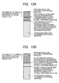
- FIGs. 13A, 13B each show a concept underlying a method for setting a threshold.
- FIGs. 13A shows the concept on the polices A, C, that is, the concept underlying a method for newly executing the intercell interference reduction.
- FIGs. 13B shows the concept on the polices B, D, that is, the concept underlying a method for stopping the intercell interference reduction.
- the longitudinal direction indicates the number, or the proportion of the terminals each having the intercell interference reduction request flag 1. There exist a region along the longitudinal direction, in which the intercell interference reduction is preferable in terms of system frequency utilization efficiency, and a region along the longitudinal direction, in which the intercell interference reduction is un-preferable.
- the intercell interference reduction is the intercell interference reduction is preferably executed the instant at which the number of the terminals each having the request flag 1 exceeds a boundary region between the preferable region and the un-preferable, and the intercell interference reduction is preferably stopped the instant at which the number of the terminals each having the request flag 1 falls short of the boundary region, however, since the number of the terminals each having the request flag 1 undergoes variation over time, if the threshold is set very close to the edge of the boundary region, the base station frequently works on other base stations, thereby raising the risk of control being un-stabilized.
- the first threshold, and the second threshold, for use in causing a chance for the base station to work on other base stations in order to execute or stop the intercell interference reduction, respectively, is kept away from the boundary region, this will enable the control to have a hysteresis, so that more stable control will be realized.
- the third and fourth thresholds for use in order that the base station passively executes or stops the intercell interference reduction upon receiving a chance from other base stations working on the base station, respectively, may be set closer to the boundary region than the first and second thresholds are.
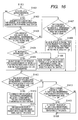
- FIG. 14 shows an operation example of the intercell interference reduction coordination unit 109.
- step S1201 an execution state of the intercell interference reduction of the relevant base station is initialized to non-execution, and the radio communication unit 201 as well is activated in a non-execution state of the intercell interference reduction.
- step S1202 processing is caused to branch according to the present state of the intercell interference reduction. That is, in this step, the processing is branched between a processing when the execution state of the intercell interference reduction is "execution" (step S1203), and a processing when the execution state of the intercell interference reduction is "non-execution” (step S1204).
- steps S1203, S1204 The processing in each of the steps S1203, S1204 will be described in detail later on, and an output thereof represents the latest execution state of the intercell interference reduction.
- state transition occurs in respect of the execution state of the intercell interference reduction.
- steps S1205, S1206, a determination is made on whether or not the state transition has occurred.
- steps S1207, S1208, respectively the base station issues a command to the radio communication unit 201 such that a radio signal is transmitted according to the latest execution state of the intercell interference reduction after the state transition.
- FIG. 15 is a flow chart showing coordinated processing (the step S1203) by the base station in the middle of execution of the intercell interference reduction.
- the policy B (refer to FIG. 12 ) of the relevant base station is valid, that is, the active stoppage is valid, the base station makes a request for stoppage of the intercell interference reduction to a peripheral base station (steps S1301, S1302) on the basis of a neighbor list held by the relevant base station.
- the base station receives a request for stoppage of the intercell interference reduction from the peripheral base station, if the policy D (refer to FIG.
- the base station transmits an OK response to the request for stoppage, transmitting an NG response if the passive stoppage is invalid (steps S1303 to S1306).
- the relevant the base station unconditionally transmits an OK response since the relevant the base station is in the middle of execution of the intercell interference reduction (steps S1307, S1308).
- the base station receives an OK response or an NG response.
- the base station formally issues a command for stoppage of the intercell interference reduction to the peripheral base station having transmitted the OK response, thereby causing the execution state of the intercell interference reduction of the relevant base station to undergo transition to "non-execution" (steps S1309 to S1311).
- the peripheral base station issues a command for stoppage of the intercell interference reduction to the relevant base station in the step S1310, the relevant base station is to receive the command.
- the relevant base station causes the execution state of the intercell interference reduction of the relevant base station to undergo transition to "non-execution" (steps 1312, S1313).
- FIG. 16 is a flow chart showing coordinated processing (the step S1204) by the base station having stopped execution of the intercell interference reduction.
- the basic operation is the same as that in FIG. 15 .
- the policy A (refer to FIG. 12 ) of the relevant base station is valid, that is, the active execution is valid
- the base station makes a request for execution of the intercell interference reduction to a peripheral base station (steps S1401, S1402) on the basis of the neighbor list (described later) held by the relevant base station.
- the base station receives a request for execution of the intercell interference reduction from the peripheral base station, if the policy C (refer to FIG.
- the base station transmits an OK response to the request for the execution, transmitting an NG response if the passive execution is invalid (steps S1403 to 1406).
- the relevant the base station unconditionally transmits an OK response since the relevant the base station is in the middle of stoppage of the intercell interference reduction (steps S1407, S1408).
- the base station receives an OK response or an NG response from the peripheral base station.
- the base station formally issues a command for execution of the intercell interference reduction to the peripheral base station having transmitted the OK response, thereby causing the execution state of the intercell interference reduction of the relevant base station to undergo transition to "execution” (steps S1409 to S1411).
- the peripheral base station issues a command for execution of the intercell interference reduction to the relevant base station in the step S1410, the relevant base station is to receive the command.
- the relevant base station causes the execution state of the intercell interference reduction of the relevant base station to undergo transition to "execution" (steps s1412, S1413).
- FIG. 17 is a view showing an example of the neighbor list to which reference is made by the base station according to the embodiment of the present invention.
- FIG. 17 shows the case where the base stations with IDs 2 to 5, respectively, exist in the neighborhood of the base station with ID 1.
- Information to which reference is made by the intercell interference reduction coordination unit 109 is concerned with the ID of a peripheral base station only, however, in order to compute a distance between the terminal - the base station, as shown in FIG. 10D , the intercell interference reduction coordination unit 109 may hold the position information on the base stations, in the form of a list.
- the neighbor list is not to be often updated, but to be updated at the time when the relevant base station is installed, and a peripheral base is additionally installed.
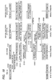
- FIG. 18 is a sequence chart for processing and control information, according to the present invention.
- the base stations each make a request for feeding back information (the received SIR, received RSSI, the propagation loss value, the received SNR, and so forth) for generation of tables shown in FIGs. 8A to 8D , respectively, to the base station, to all the terminals belonging to the base station itself (step S1501).
- the terminals each feed back information based on results of measurement taken in step S1502 to the base station by use of an upstream control channel.
- the base stations each receive the information fed back from all the terminals belonging to the base station itself via the radio communication unit 201, and subsequently, determine whether or not the intercell interference reduction is to be executed on the terminal-by-terminal basis (step S1503) in accordance with a procedure shown in FIG. 9 in the operation of the terminal distribution checking unit 107 shown in FIG. 7 , thereby preparing tables shown in FIGs. 10A to 10D , respectively.
- the base station determines whether the following four policies each are valid or invalid (step S1504) in accordance with a procedure shown in FIG. 11 , thereby preparing a table shown in FIG. 12 :
- the base station finally makes a determination on whether or not the intercell interference reduction is to be executed by the respective base stations in accordance with procedures shown in FIGs. 14 to 16 , respectively, (steps S1505 to S1508).
- the intercell interference reduction coordination unit 109 issues a command for execution, or stoppage of the intercell interference reduction to the radio communication unit 201, and the radio communication unit 201 adjusts a transmission output of a signal, as shown in FIG. 2A , or 2B , in accordance with the command (step S1509).
- communication between the base stations communication between the base stations is executed through a backhaul network via the backhaul communication unit 202.
- intercell interference reduction coordination unit 109 is described with reference to the sequence chart of FIG. 18 .
- the base station If the policy A (active execution) is found valid after the intercell interference reduction execution determination unit 108 has made the determination for execution of the intercell interference reduction, having prepared the table shown in FIG. 12 , the base station transmits a request for execution of the intercell interference reduction to peripheral base stations on the basis of the neighbor list of FIG. 17 . Similarly, if the policy B (active stoppage) is valid, the base station transmits a request for stoppage of the intercell interference reduction to the peripheral base stations (the step S1505).
- the peripheral base station having received either of the requests transmits a response to the request, based on its own table in FIG.12 , to the base station at a transmission source of the request (the step S1506). If the policy C (passive execution) of the peripheral base station having received the request is valid, and the request for execution of the intercell interference reduction is received, the peripheral base station transmits an OK response to the transmission source of the request. Similarly, if the policy C (passive execution) of the peripheral base station having received the request is invalid, and the request for execution of the intercell interference reduction is received, the peripheral base station transmits an NG response to the transmission source of the request.
- the peripheral base station transmits an OK response to the transmission source of the request.
- the peripheral base station transmits an NG response to the transmission source of the request.
- the peripheral base station transmits an OK response to the transmission source of the request.
- the peripheral base station transmits an OK response to the transmission source of the request.
- Processing described as above corresponds to the processing in the steps S1303 to S1308, and the steps S1403 to S1408.
- the base station When a base station at a request source has received an OK response from at least one of the peripheral base stations, the base station transmits a command for execution of intercell interference reduction, or stoppage of the intercell interference reduction to a peripheral base station at a transmission source of the OK response (the step S1507) in order to actually execute, or stop the intercell interference reduction.
- the peripheral base station having received the command causes an execution state of the intercell interference reduction of the peripheral base station itself to undergo transition to execution, or non-execution, thereby transmitting ACK to the base station at a transmission source of the command (the step S1508).
- the peripheral base station causes an execution state of the intercell interference reduction of the base station having received ACK at the transmission source of the command to undergo transition to execution, or non-execution (the step S1509).
- the base station that has caused the execution state of the intercell interference reduction of the base station itself to undergo transition to execution, or non-execution alters a signal transmission method using the radio communication unit 201 to that shown in, for example, FIG. 2B in the case of the transition to execution, or to that shown in, for example, FIG. 2A in the case of the transition to non-execution.
- the base station at the request source has not received an OK response at all, or has received an NG response only, the base station does not transmits any command to the peripheral base station.
- the processing described in the foregoing is an operation in one cycle, and the base stations each work on various parties by starting with a request for information, made to the terminals, thereby repeating the operation thereafter.
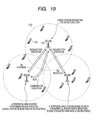
- FIG. 19 is a view showing flows of message exchange in the sequence chart shown in FIG. 18 .
- Three base stations each represent "a base station requesting for active execution of intercell interference reduction", with terminals distributed only on a cell boundary, "a peripheral base station performing passive execution", with most of terminals distributed on a cell boundary, and "a peripheral base station having no need for intercell interference reduction", with most of terminals distributed inside a cell.
- the base station requesting for active execution of intercell interference reduction is to make a request for active execution of intercell interference reduction to two peripheral base stations as the processing in the step S1505 in FIG. 18 .
- the respective peripheral base stations transmit an OK response, or an NG response to the base station at the request transmission source as the processing in the step S1506 in FIG. 18 .
- the base station at the request transmission source has received the OK response from one of the peripheral base stations, so that the base station has transmitted a command for execution of the intercell interference reduction to "the peripheral base station performing passive execution", having transmitted the OK response, as the processing in the step S1507 in FIG. 18 .
- the peripheral base station performing passive execution having received the command, decodes the command as the processing in the step S1508 in FIG. 18 , thereby transmitting ACK to the base station at a command transmission source.
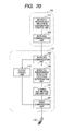
- FIG. 20 shows a second embodiment of the invention.
- This embodiment represents the case where part of the function of the base station 101 shown in FIG. 7 is transferred to a gateway 104.
- the second embodiment has a feature in that there is an increase in communication between the gateway 101 and the base stations 101, and a throughput of the gateway 104 itself.
- the gateway 101 communicates with one, or plural the base stations 101 by use of the backhaul communication unit 202.
- the respective base stations 101 transfer results of the output (refer to FIG. 12 ) of the intercell interference reduction execution determination unit 108 to the gateway 104, and the gateway 104 transmits an execution state (execution or non-execution) of intercell interference reduction of each of the base stations 101 to the respective base stations.
- the respective base stations 101 decode the execution state (execution or non-execution) of the intercell interference reduction, received from the gateway 104 via the backhaul communication unit 202, with the use of an output control unit 110, thereby issuing a command for output adjustment (such adjustment as shown in FIG. 2A in the case of the execution state of the intercell interference reduction being non-execution, or such adjustment as shown in FIG. 2B in the case of the execution state of the intercell interference reduction being execution) to the radio communication unit 2
- the processing of the intercell interference reduction coordination unit 109 described with reference to FIGs. 14 to 16 is performed by an intercell interference reduction coordination-control unit 111 inside the gateway 104.
- the gateway 104 repeatedly performs the processing in each of the steps S1201 and so forth against all the base stations 101 under control of the gateway 104 itself.
- this unit that the processing in the step S1202 is applied to all the base stations after the processing in the step S1201 is applied to all the base stations.
- a thread may be run on a base station-by-base station basis, thereby performing a multi-threaded processing.
- Execution of flag management inside the gateway 104 can be substituted for the request for execution of the intercell interference reduction, the request for stoppage of the intercell interference reduction, the OK response, the NG response, the command for execution of the intercell interference reduction, the command for stoppage of the intercell interference reduction, and ACK, for use in actual communication between the base stations as described with reference to FIGs. 14 to 16 .
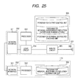
- FIG. 25 shows the configuration in case of a base station 101 and a gateway 104 in FIG. 20 .
- Programs to be stored in this embodiment are such executive programs as the terminal distribution checking unit 107, the intercell interference reduction execution determination unit 108, and the output control unit 111.
- the gateway 104 is composed of a network interface device 301 which complies with the IEEE802.3 communication standard and which corresponds to the backhaul communications unit 202, a processor 302 which executes the intercell interference reduction coordination unit 111, a memory 303 which stores an executive program of the intercell interference reduction coordination unit 111.
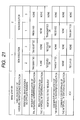
- FIG. 21 is a view showing an example of the flag management inside the gateway.
- the gateway 104 manages flags, the flags each indicating exchange of control information, such as the request for execution of the intercell interference reduction, and so forth, on a base station-by-base station basis.
- This example is concerned with a base station with ID 1, and a base station with ID 2, showing an example of the flag management when the execution state of the intercell interference reduction of each of the base stations is "non-execution"
- the base stations each hold two base stations, that is, base stations with ID 2, and ID 3, respectively, and base stations with ID 1, and ID 3, respectively, as peripheral base stations to be managed according to the neighbor list.
- the base station with ID 1 transmits a request for execution of intercell interference reduction to the peripheral base stations (ID 2, ID 3).
- the base station with ID 2 receives the request for the execution of the intercell interference reduction from the base station with ID 1.
- the base station with ID 2 transmits an OK response against the request to the base station with ID 1, and the base station with ID 1 receives the OK response. However, the base station with ID 1 receives an NG response from the base station with ID 3.
- the flag management executed inside the gateway can be substituted for communication between the base stations.
- the base station with ID 1 at an issuance source of the command for the execution of the intercell interference reduction together with the base station with ID 2 having received the command for the execution of the intercell interference reduction, causes the execution state of the intercell interference reduction to make a transition from non-execution to execution. Further, with respect to the base station with ID 3 that have neither transmitted, nor received the command for the execution of the intercell interference reduction, state transition does not occur.
- FIG. 22 is a sequence chart of the second embodiment of the invention.
- a mechanism for effecting information aggregation to the gateway, and causing the gateway to notify the result of a state transition to the respective base stations is added to the sequence chart shown in FIG. 18 .
- the gateway makes a request to the respective base stations for transmission of intercell interference reduction execution determination results, as the output results of the intercell interference reduction execution determination unit 108, to the gateway (step S1601).
- This operation is performed by the intercell interference reduction coordination-control unit 111 via the backhaul communication unit 202.
- the respective base stations upon receiving the request from the gateway, collect information from respective terminals in accordance with procedures shown in FIGs. 9 , and 11 , respectively, to generate the intercell interference reduction execution determination results shown in FIG. 12 , thereby transmitting the determination results to the gateway (the steps S1501 to1504).
- the intercell interference reduction coordination-control unit 111 of the gateway aggregates the determination results with respect to all the base stations (step S1602), and perform such processing as described with reference to FIGs. 20 , 21 , thereby generating the latest execution state of the intercell interference reduction (execution, or non-execution) with respect to each of the base stations (step S1603).
- the gateway notifies the latest execution state as the latest state to the respective base stations, whereupon the respective base stations decode the latest state with the use of the output control unit 110, thereby issuing a command for an output method corresponding to the latest state to the radio communication unit 201 (the step S1509).
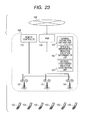
- FIG. 23 shows a third embodiment of the invention.
- This embodiment differs from the first embodiment, and the second embodiment in that a remote controller 112 for performing maintenance of the base station 101 at remote locations is incorporated in the backhaul network 105.
- the present embodiment is identical to the second embodiment except that the function performed by the gateway 104 in the second embodiment is implemented by the remote controller 112.
- the remote controller 112 is substituted for the gateway 104 shown in FIG. 20 , and if the gateway shown in FIG. 22 is read as the remote controller, the present invention can be carried out by use of a method identical to that in the case of the second embodiment.
- the present embodiment has a feature that a load imposed on the gateway 104 in the second embodiment is undertaken by the remote controller 112, so that to the load can be dispersed, thereby lessening the load imposed on the gateway 104.
- the radio communications system With the radio communications system according to the present invention, it is possible to enhance the communication quality of the terminal at the cell boundary while preventing deterioration in frequency utilization efficiency of the system as a whole as much as possible. As a result, it is possible to realize the trade-off between high frequency utilization efficiency of the system as a whole, and control of dispersion in service quality of the terminal, dependent on a distance from the base station.
Landscapes
- Engineering & Computer Science (AREA)
- Quality & Reliability (AREA)
- Computer Networks & Wireless Communication (AREA)
- Signal Processing (AREA)
- Mobile Radio Communication Systems (AREA)
Applications Claiming Priority (1)
| Application Number | Priority Date | Filing Date | Title |
|---|---|---|---|
| JP2009041664A JP2010199910A (ja) | 2009-02-25 | 2009-02-25 | 無線通信システム、基地局、端末及び通信装置 |
Publications (2)
| Publication Number | Publication Date |
|---|---|
| EP2224765A2 true EP2224765A2 (de) | 2010-09-01 |
| EP2224765A3 EP2224765A3 (de) | 2012-01-18 |
Family
ID=42115997
Family Applications (1)
| Application Number | Title | Priority Date | Filing Date |
|---|---|---|---|
| EP10001670A Withdrawn EP2224765A3 (de) | 2009-02-25 | 2010-02-18 | Funkkommunikationssystem, Basisstationsvorrichtung, Gateway-Vorrichtung und Fernsteuerung |
Country Status (4)
| Country | Link |
|---|---|
| US (1) | US20100216450A1 (de) |
| EP (1) | EP2224765A3 (de) |
| JP (1) | JP2010199910A (de) |
| CN (1) | CN101815356A (de) |
Cited By (1)
| Publication number | Priority date | Publication date | Assignee | Title |
|---|---|---|---|---|
| EP2393230A3 (de) * | 2010-06-03 | 2012-03-14 | Hitachi, Ltd. | Basisstation |
Families Citing this family (10)
| Publication number | Priority date | Publication date | Assignee | Title |
|---|---|---|---|---|
| WO2011148211A1 (en) * | 2010-05-26 | 2011-12-01 | Telefonaktiebolaget L M Ericsson (Publ) | Methods and systems for user equipment positioning using intercell interference coordination |
| US9203575B2 (en) | 2010-11-05 | 2015-12-01 | Hitachi, Ltd. | Wireless communication system, base station, and wireless communication method |
| CN102843697B (zh) * | 2011-06-22 | 2015-09-30 | 电信科学技术研究院 | 异系统间频谱共享情况下的干扰抑制方法和设备 |
| JP5785860B2 (ja) * | 2011-11-30 | 2015-09-30 | 株式会社日立製作所 | 基地局及び干渉制御方法 |
| KR20130088572A (ko) * | 2012-01-31 | 2013-08-08 | 삼성전자주식회사 | 상향링크 신호 채널을 이용한 다중 셀 협력을 위한 기지국과 서버의 자원 할당 방법 및 그 장치 |
| KR20130090669A (ko) * | 2012-02-06 | 2013-08-14 | 삼성전자주식회사 | 이종 네크워크에서 셀간 간섭을 조정하는 중앙집중형 스케쥴링 방법 및 장치 |
| US8964704B2 (en) * | 2013-03-29 | 2015-02-24 | Via Telecom Co., Ltd. | System and method of enhanced pilots for improved mobile station positioning |
| KR102143424B1 (ko) * | 2016-12-09 | 2020-10-15 | 한국전자통신연구원 | 서비스 레벨에 기초한 접속 제어 방법 및 장치 |
| EP3769446B1 (de) * | 2018-03-19 | 2021-11-17 | Signify Holding B.V. | Interferenzhandhabung für drahtlose netzwerke mit mehreren koordinatoren |
| CN109728871B (zh) * | 2019-01-10 | 2020-05-15 | 郑州轻工业大学 | 一种基于功率动态分配的干扰利用方法、无线通信系统 |
Citations (1)
| Publication number | Priority date | Publication date | Assignee | Title |
|---|---|---|---|---|
| US20070086406A1 (en) | 2005-10-03 | 2007-04-19 | Texas Instruments Incorporated | Methods for Assigning Resources in a Communication System |
Family Cites Families (3)
| Publication number | Priority date | Publication date | Assignee | Title |
|---|---|---|---|---|
| US7162250B2 (en) * | 2003-05-16 | 2007-01-09 | International Business Machines Corporation | Method and apparatus for load sharing in wireless access networks based on dynamic transmission power adjustment of access points |
| US7558577B2 (en) * | 2005-11-10 | 2009-07-07 | Motorola, Inc. | Methods for dividing base station resources |
| CN101034927A (zh) * | 2006-03-06 | 2007-09-12 | 松下电器产业株式会社 | 降低小区间/内干扰的多用户多天线上行发送-接收方法 |
-
2009
- 2009-02-25 JP JP2009041664A patent/JP2010199910A/ja active Pending
-
2010
- 2010-02-11 CN CN201010115615A patent/CN101815356A/zh active Pending
- 2010-02-18 EP EP10001670A patent/EP2224765A3/de not_active Withdrawn
- 2010-02-22 US US12/709,860 patent/US20100216450A1/en not_active Abandoned
Patent Citations (1)
| Publication number | Priority date | Publication date | Assignee | Title |
|---|---|---|---|---|
| US20070086406A1 (en) | 2005-10-03 | 2007-04-19 | Texas Instruments Incorporated | Methods for Assigning Resources in a Communication System |
Non-Patent Citations (1)
| Title |
|---|
| NORTEL: "3GPP DRAFT", vol. RAN WG1, 3 April 2007, MOBILE COMPETENCE CENTRE, article "Further Discussion on Adaptive Fractional Frequency Reuse" |
Cited By (2)
| Publication number | Priority date | Publication date | Assignee | Title |
|---|---|---|---|---|
| EP2393230A3 (de) * | 2010-06-03 | 2012-03-14 | Hitachi, Ltd. | Basisstation |
| US8744362B2 (en) | 2010-06-03 | 2014-06-03 | Hitachi, Ltd. | Base station |
Also Published As
| Publication number | Publication date |
|---|---|
| JP2010199910A (ja) | 2010-09-09 |
| US20100216450A1 (en) | 2010-08-26 |
| CN101815356A (zh) | 2010-08-25 |
| EP2224765A3 (de) | 2012-01-18 |
Similar Documents
| Publication | Publication Date | Title |
|---|---|---|
| EP2224765A2 (de) | Funkkommunikationssystem, Basisstationsvorrichtung, Gateway-Vorrichtung und Fernsteuerung | |
| US10104558B2 (en) | Joint optimization of a radio access network and a distributed antenna system | |
| US8717983B2 (en) | Mechanism of dynamic resource transaction for wireless OFDMA systems | |
| US9516508B2 (en) | System and method for heterogenous spectrum sharing between commercial cellular operators and legacy incumbent users in wireless networks | |
| US8670773B2 (en) | Control device, communication system, resource allocation method, and recording medium containing program | |
| KR102077831B1 (ko) | 무선 네트워크의 무선 자원 관리 방법 및 장치 | |
| US20140098695A1 (en) | Apparatus and method for transmitting/receiving feedback information in a wireless communication system using beamforming | |
| US9258785B2 (en) | Uplink signal transmitting and receiving method and device in a wireless communication system | |
| KR20120059989A (ko) | 대상 단말 및 협력 단말의 협력 통신 방법 | |
| EP3185435A1 (de) | Mehrzelliges strahlenbündelungsverfahren und vorrichtung | |
| US9078273B2 (en) | Base station, communication terminal, usable radio resource setting method, and base station control program | |
| US9648624B2 (en) | Semi-decentralized scheduling in a wireless network | |
| KR101981089B1 (ko) | 이종셀 무선 통신 시스템에서 셀을 선택하는 방법 및 장치 | |
| KR101584960B1 (ko) | 통신 시스템에서 기지국 간 정보 교환을 통한 간섭 제어 장치 및 방법 | |
| US10382176B2 (en) | Method and apparatus for determining multi-point transmission resource | |
| CN105393573A (zh) | 一种干扰控制方法、装置及网元设备 | |
| EP4598109A1 (de) | Drahtloses kommunikationssystem, drahtloses kommunikationsverfahren, clustering-verwaltungsvorrichtung und programm | |
| US20230028383A1 (en) | Beam optimization based on signal measurements in neighboring cells |
Legal Events
| Date | Code | Title | Description |
|---|---|---|---|
| PUAI | Public reference made under article 153(3) epc to a published international application that has entered the european phase |
Free format text: ORIGINAL CODE: 0009012 |
|
| 17P | Request for examination filed |
Effective date: 20100311 |
|
| AK | Designated contracting states |
Kind code of ref document: A2 Designated state(s): AT BE BG CH CY CZ DE DK EE ES FI FR GB GR HR HU IE IS IT LI LT LU LV MC MK MT NL NO PL PT RO SE SI SK SM TR |
|
| AX | Request for extension of the european patent |
Extension state: AL BA RS |
|
| PUAL | Search report despatched |
Free format text: ORIGINAL CODE: 0009013 |
|
| AK | Designated contracting states |
Kind code of ref document: A3 Designated state(s): AT BE BG CH CY CZ DE DK EE ES FI FR GB GR HR HU IE IS IT LI LT LU LV MC MK MT NL NO PL PT RO SE SI SK SM TR |
|
| AX | Request for extension of the european patent |
Extension state: AL BA RS |
|
| RIC1 | Information provided on ipc code assigned before grant |
Ipc: H04W 72/08 20090101AFI20111213BHEP |
|
| 17Q | First examination report despatched |
Effective date: 20130111 |
|
| STAA | Information on the status of an ep patent application or granted ep patent |
Free format text: STATUS: THE APPLICATION IS DEEMED TO BE WITHDRAWN |
|
| 18D | Application deemed to be withdrawn |
Effective date: 20130522 |