EP2226014B1 - Augenprobenvorrichtung - Google Patents
Augenprobenvorrichtung Download PDFInfo
- Publication number
- EP2226014B1 EP2226014B1 EP09305209A EP09305209A EP2226014B1 EP 2226014 B1 EP2226014 B1 EP 2226014B1 EP 09305209 A EP09305209 A EP 09305209A EP 09305209 A EP09305209 A EP 09305209A EP 2226014 B1 EP2226014 B1 EP 2226014B1
- Authority
- EP
- European Patent Office
- Prior art keywords
- sampling
- supporting means
- eye
- rest position
- sampling surface
- Prior art date
- Legal status (The legal status is an assumption and is not a legal conclusion. Google has not performed a legal analysis and makes no representation as to the accuracy of the status listed.)
- Not-in-force
Links
Images


Classifications
-
- A—HUMAN NECESSITIES
- A61—MEDICAL OR VETERINARY SCIENCE; HYGIENE
- A61B—DIAGNOSIS; SURGERY; IDENTIFICATION
- A61B10/00—Instruments for taking body samples for diagnostic purposes; Other methods or instruments for diagnosis, e.g. for vaccination diagnosis, sex determination or ovulation-period determination; Throat striking implements
- A61B10/02—Instruments for taking cell samples or for biopsy
Definitions
- the invention relates to a device with which conjunctival impressions may be taken.
- the conjunctival impression technique was developed at the end of the 1970s and is now an accepted technique allowing conjunctival epithelial cells to be collected from the conjunctival mucosa which is an immunologically reactive and complex tissue, in a quasi-painless and non-invasive way, for purposes of analyses and diagnose.
- the most superficial cells of the conjunctival epithelium i.e. the cells undergoing desquamation, are collected by this technique.
- Conjunctival epithelium renews itself from the basal layers, and the most superficial cells which have reached their final differentiation are regularly discharged into the lachrymal fluid. It is this surface layer comprising the terminally differentiated conjunctival cells, which may be sampled by the conjunctival impression for subsequent analysis.
- the most current present method consists in using membrane filters commonly used in biochemical industry, the most often in cellulose ester (a mixture of cellulose ester and cellulose nitrate) or in polyethersulfone, for example, and which are applied on the conjunctiva, generally without any local anesthesia (See Margarita Calonge et al., Impression cytology of the ocular surface: a review, Experimental Eye Research, 78 (2004), p 457-472 ).
- the sampling is totally bloodless, painless and non-invasive contrary to other more aggressive systems such as brushing or biopsy.
- the filter is generally applied on the upper bulbar conjunctiva of the eye, protected by the eyelid and removed after a contact of 3-5 seconds.
- the desquamating conjunctival cells then adhere to the membrane surface and form a thin and homogenous cell layer.
- the filters are then treated in order to recover the cells to be analyzed.
- Document US 5 137 030 discloses another method and device for taking a conjunctival impression wherein the device comprises a handle portion and a body portion, which is slotted for scraping conjuctival cells into the slots.
- An object of the invention is to provide a device for taking an eye impression which is simple to implement while supplying reliable and reproducible sampled impressions.
- an eye sampling device comprising supporting means comprising a sampling surface, the supporting means being elastically deformable between a rest position and a sampling position and conformed so that, upon being used for sampling, the sampling surface applied in the sampling position in a coinciding way onto a sampling area (2;402;502), is detached therefrom according to a peeling movement when passing from the sampling position to a rest position.
- the device according to the invention has at least one of the following features:
- the sampling area 2 of an eye impression is located on the conjunctiva, an area located at the periphery of the cornea, which extends from the limbus which delimits the junction between the cornea (nominal diameter of the cornea: about 12 mm for an adult) and the sclera, and extends outwardly to an area externally delimited by a circle with a diameter of about 22 mm and centered on the cornea.
- the sampling area 2 (and therefore the sampling surface 11) is ring-shaped with an inner diameter of about 12 mm and an outer diameter of about 17 mm. For a child, whose eye has not reached the adult size, these dimensions have to be adapted in proportion.
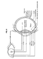
- the area 2 for taking an eye impression is moreover located on the eyeball which may be assimilated to a sphere with a diameter of 24 mm +/- 1 mm, except at the cornea.
- the eye's anatomy is recalled and illustrated in Fig. 8 .
- This kinematics is important in order to ensure reliability and reproducibility as well as quality of the eye impressions taken by means of the device 10 according to the invention in order to maximize the quality of the sampled cells while maintaining their integrity.
- the device 10 includes a piston forming component 30 having an end 22 on which supporting means 12 are attached.
- These supporting means 12 are elastically deformable between a rest position illustrated in Fig. 1a and a sampling position illustrated in Fig. 1b .
- these supporting means include a sampling face or surface 11 which is intended to face and to be pressed against a sampling area 2 of an eye 1.
- This sampling surface is made in one or more suitable materials forming a support for taking eye impressions and moreover known to one skilled in the art.
- the sampling surface when the supporting means 12 are in the rest position, has at least one low point 121 (or low contact line) and at least one high point 122 (or high contact line), along a longitudinal axis of the device depending on the direction in which a sampling movement is performed.
- sampling movement is obtained by presenting the sampling surface 11 in a non-parallel or non-coinciding way towards the sampling area 2 of the eye surface.
- the sampling surface 11, defined by a planar geometry here is presented so as to face the sampling area 2 of the eye surface according to a given orientation, so that, at the time of contact between both surfaces, there is no coincidence of these surfaces.
- contact between the sampling surface 11 and the sampling area 2 of the eye 1 is initiated by the contact of the low point (or low line) 121 on said sampling area and proceed by moving this contact point (or line) along the sampling surface 11, by sweeping through the latter, right up to the high point (or high line) 122 which lastly comes into contact with the sampling area 2, and this under the effect of a movement along the longitudinal axis of the device 10 according to the invention as illustrated by the arrow of Fig. la.
- the sampling surface 11 gradually deforms so as to become coincident with the sampling area 2 of the eye surface.
- the sampling support once it is placed on the eye 1, is then detached from the eye 1 in the least traumatic way, by exerting a peeling movement.
- concentrated stresses may exist at the location of the detachment which, here, is a point on the schematic view of Figs. 1a and 1b (or a line passing through this point) and which, during detachment, passes from the high point (or high line) 122 to the low point (or low line) 121, while the sampling surface 11 under the effect of the supporting means 12 which gradually resume their initial resting shape under the effect of the elastic forces, initial shape which does not coincide with the sampling area 2 of the eye 1.
- the supporting means 12 are made in a block of elastically deformable material such as a foam or a suitable elastomer (elastic polymer): polyurethane, polyethylene, silicone foam, a thermoplastic elastomer such as Styrene-ethylene/butylene-styrene (SEBS), Styrene-ethylene/propylene-styrene (SEPS) ethylene-propylene copolymer/polypropylene (EPDM-PP), polyether block amides (PEBAX), polyurethane or further a vulcanizable elastomers such as silicone rubber, latex, polybutadiene, a fluorinated elastomer, polychloroprene, polyisoprene...etc.
- a suitable elastomer elastic polymer
- FIGs. 2a and 2b Two alternative embodiments of the supporting means are illustrated in Figs. 2a and 2b .
- the supporting means are produced as a flexible blade 112 mounted on the component 20 forming a piston via a supporting rod.
- the supporting means are produced as a plate supported by spring blades 212, for example made in plastic, in metal or any other material having similar elastic properties.
- the sampling surface alternatively has different convex sectional geometries:
- the sampling surface 111,211,311 always has a low point and at least one high point in order to be able to allow the sampling movement according to the kinematics described earlier, with reference to Figs. 1a and 1b .
- the contact between the sampling surface 11,111,211,311 and the sampling area 2 of the eye surface is gradually made and as a dynamic contact point or/and then line gradually sweeping through the sampling area right up to intimate contact between both surfaces, the sampling surface being deformed as well as the supporting means.
- the progressive movement of this same dynamic contact line is the inverse of the movement performed during the contacting.
- the detachment movement is analogous to a peeling movement with which the cells of the sampling area 2 may be gradually detached from the eye surface, which have then adhered onto the sampling support of the sampling surface.
- This adhesion on the sampling support is achieved according to different well-known principles: by hydrophilicity, by standard surface tension, by adhesion of the cell mucus, or anionic electrostatic charges of the cells.
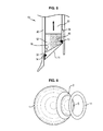
- the device 10 here is ring-shaped with a longitudinal axis X-X. It includes a piston 20.
- the piston 20 includes an upper end 23 comprising an interface for applying said piston 20.
- the supporting means 12 includes an opposite end 22 substantially perpendicular to the longitudinal axis X-X on which the supporting means 12 are positioned and attached, here as a sectional shape of a elastomeric trapezoidal block (or of a block formed with a truncated cylinder, an upper end of which is perpendicular to the axis, in contact on the end 22 of the piston 20 and an opposite lower face tilted with respect to said axis).
- These supporting means 12 as seen earlier, are elastically deformable between a rest position and a sampling position. An end of the supporting means 12, tilted with respect to the longitudinal axis, bears the sampling surface 11.
- This sampling surface 11 includes the sampling support intended to collect an eye impression upon sampling on a sampling area 2 of the eye 1.
- the sampling support includes at the periphery, around the sampling surface 11, a flexible edge 13, 14 (added by insert-molding, adhesive bonding, welding...etc.), this edge having a protrusion directed radially towards the supporting means 12, which will fit onto a notch 15, 16 located on the perimeter of the supporting means 12. Once it is in place, the edge 13, 14 extends and protrudes from the supporting means 12.
- the sampling support is itself also ring-shaped and includes a first edge 13 on a radially inner periphery and a second edge 14 on a radially outer periphery.
- the supporting means 12 are ring-shaped and include a first notch 15 on a radially inner face into which the protrusion of the first edge 13 will fit and a second notch 16 on a radially outer face into which the protrusion of the second edge 14 will fit.
- the piston 20 is slidably mounted in a body 30 of the device 10 according to the invention and this against an elastic return means 21, here as a compression spring.
- the body 30 includes a first radially inner wall including an end 32 intended to come into contact with the eye 1 during sampling. Additionally, the radially inner wall of the body 30 includes a radially outer shoulder 34, optionally with a frusto-conical shape, the role of which will be described subsequently with reference to Fig. 5 .
- the end 32 of the device 10 according to the invention includes a semi-circular supporting area intended to come into contact, by fitting its contour, with the limbus L of the eye 1, thereby ensuring proper positioning on the one hand and properly maintaining the relative position between the eye and the device according to the invention during the sampling, on the other hand.
- the body 30 further includes a second radially outer wall comprising an end 31 intended to come into contact with the eye 1 during sampling. Additionally, the radially outer wall of the body 30 includes a radially inner shoulder 33, the role of which will be described subsequently with reference to Fig. 5 .
- the edges of the eyelids are often contaminated by bacterial strains different from those present at the eye surface, there is a risk of contamination of the taken sample specifically dedicated to the analysis of this surface. Consequently, before putting the sampling support in contact with the sampling area of the eye, the surface including the sampling area of the edge of the eyelids has to be isolated. This is the role of the end 31 which is conformed in order to face the eyelid, by being accommodated below the eyelid, while maintaining the latter open and preventing any crossed contamination between the sample and the eyelid.
- the end 31 has a foot-shaped section, the sole of which has a section of a concave shape mating that of the eye surface upon which the end 31 is intended to bear during sampling, the eyelid will then come into contact and be retained by the top of said foot.
- the eye surface is covered with a lachrymal film consisting of tears and of a thin layer of lipids secreted by the Meibomian glands located at the lid margin of the lower and upper eyelids.
- This thin lipidic and hydrophobic layer will limit or prevent adhesion of the cells on the highly hydrophilic surface of the sampling support. Consequently, before having the sampling support come into contact with the sampling area of the eye, the tear film has to be broken. This is the additional role of the ends 31 and 32 of the body 30.
- these ends 31 and 32 are made in or covered with a semi-rigid or elastomeric (so as not to injure the eye surface and to achieve intimate contact with the latter) material and which is both absorbent and lipophilic so as to absorb the lipid portion of the tear film at the sampling area of the sampling surface thereby delimited by these ends 31 and 32.
- the device 10 according to the invention is placed on the eye 1 so that the end 32 of the body 30 will contact the limbus L and that the end 31 of the body 31 is inserted under the eyelids.
- pressure is exerted on the end 23 of piston 20 in order to accomplish the sampling. This pressure is exerted along the longitudinal axis X-X and oriented towards the eye 1 (see the arrow of Fig. 4 ).
- the sampling support 11 is then pressed on the eye according to the sampling kinematics which was described earlier with reference to Figs. 1a and 1b .
- the pressure on the end 23 of the piston 20 is released, the so compressed springs 24 exert a return force on the piston 20 forcing it to slide in the body 30 along the longitudinal axis X-X in the direction of the arrow as illustrated in Fig. 6 .
- the sampling support 11 is driven by the piston and is delicately detached according to the peeling movement described earlier. There is no suction cup effect between the sampling support 11 and sampling area 2 of the eye. The device 10 is then removed from the eye.
- sampling support 11 remains to be recovered in order to be able to carry out the intended analyses.
- Recovery of the sampling support 11 is performed after having placed at least the portion including the sampling support 11 of the device according to the invention inside a collecting means, such as for example a collecting tube.
- the piston 20 is then pulled backwards according to the arrow of Fig. 6 and the edges 14 and 13 of the sampling support 11 will bear upon the shoulders 33 and 34 of the body 30. As the movement of the piston 20 being pulled backwards continues, the edges 14 and 13 retained by the shoulders 33 and 34, each protrusion of the edges 14 and 13 are then disengaged from the notches 16 and 15 of the supporting means 12, respectively. The sampling support 11 is detached and falls into the collecting means.
- the detachment of the sampling support 11 is carried out according to a gradual movement defined by the initial position of the shoulders 33 and 34 along the travel covered by the piston 20 when it is pulled backwards in the body 30: the edge 14 will first bear upon the shoulder 33 and its protrusion disengages from the notch 16, and then the edge 14 will first bear upon the shoulder 34 and its protrusion disengages from the notch 15, thereby releasing the sampling support 11.
- the shoulders 33 and 34 are not located at a same height along the axis of the device and the edges 14 and 13 themselves are not at the same height, which is the case in the example of Fig. 5 .
- the shoulders 33 and 34 are located at a same height along the axis of the device and the edges 14 and 13 themselves are not at the same height. In still another alternative, the shoulders 33 and 34 are not located at a same height along the axis of the device and the edges 14 and 13 themselves are at the same height.
- the sampling support 11 falls into the collecting means without any other handling from behalf of the user and with very limited contact with open air. This thereby reduces the risks of accidental contamination (desirable for analyzing the germs present at the eye surface and detecting infestations of microorganisms, for example) and of damage before utilization. Indeed, cytology for example requires the cells to be very well attached onto the sampling support 11 so as to be marked with fluorescent markers and allow observation by conventional microscopy (with transparization of the support) or confocal microscopy.
- Cytometry as for it, requires the cells to adhere as much as possible on the support, while allowing to be easily detached when desirable into a collecting solution with order to proceed to cell counting and sorting.
- eye impressions may be optimized to the various kinds of analysis techniques by using different supports adapted to the analysis procedure.
- the sampling support 11 is here an insert-molded membrane filter type with a flexible plastic edge (which has the advantage of being a versatile solution, allowing the use of several types of membranes).
- a shaped one-piece part membrane + edge
- a treated surface optimized for the sampling (roughness, plasma treatment in order to increase hydrophilicity,...etc.) in order to produce the sampling support.
- the device 10 therefore provides control of the two following parameters when placing and removing the sampling support, for making the samplings more reliable:
- the problem of the tear film may be solved, and the sampling surface may be defined and localized always at the same location and the eye may be immobilized, as well as recovery may be optimum without damaging the taken eye impression.
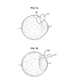
- the device according to the invention which has just been described according to one embodiment, where it has an axisymmetrical ring shape, may appear in any geometrical (sector, round, oval, ovoid ...etc.) shape able to be inscribed between the diameter at the limbus and the diameter of about 22 mm.
- a first alternative embodiment illustrated in Fig. 7a delimits a sampling area 402 (and so the sampling support 411) formed by a half-disc with a diameter of about 13 mm, the centre of which is tangential at the limbus and placed on the upper area of the conjunctiva.
- the disc is inscribed in the ring-shaped sampling surface with an inner diameter of about 12 mm and an outer diameter of about 18.5 mm in this case.
- a second alternative embodiment illustrated in Fig. 7b delimits a sampling area 502 (and so the sampling support 511) as a sector with an inner diameter of about 12 mm at the limbus and an outer diameter of about 17 mm.
- the shoulders 33 and 34 form a single and same shoulder inside the body of the device, as well as the notches 13 and 14 which are only a single notch at the periphery of the supporting means 12.
- the device according to the invention described earlier therefore operates by having the conjunctiva come into contact with a material allowing controlled adhesion of the cells. Most particularly, it ensures that:
- sampling support 11 The material allowing the sampling and forming the sampling support 11 (foam, woven or non-woven fabric filter, hydrogel, polymer whether treated or not...etc.) is compatible with the present methods of analysis, i.e:
- exemplary uses of the taken sample may relate to recovery of DNA (within the scope of forensic medicine for example) or to the analysis of germs present at the eye surface (viruses and bacteria).
Landscapes
- Health & Medical Sciences (AREA)
- Life Sciences & Earth Sciences (AREA)
- Surgery (AREA)
- Animal Behavior & Ethology (AREA)
- Biomedical Technology (AREA)
- Heart & Thoracic Surgery (AREA)
- Medical Informatics (AREA)
- Molecular Biology (AREA)
- Pathology (AREA)
- Engineering & Computer Science (AREA)
- General Health & Medical Sciences (AREA)
- Public Health (AREA)
- Veterinary Medicine (AREA)
- Investigating Or Analysing Biological Materials (AREA)
- Sampling And Sample Adjustment (AREA)
- Apparatus Associated With Microorganisms And Enzymes (AREA)
- Eye Examination Apparatus (AREA)
Claims (13)
- Augen-Probenahmevorrichtung (10), die eine Halteeinrichtung (12; 112; 212) mit einer Probenahmefläche (11; 111; 211; 311; 411; 511) aufweist, dadurch gekennzeichnet, dass die Halteeinrichtung zwischen einer Ruheposition und einer Probenahmeposition elastisch verformbar und so angepasst ist, dass bei Gebrauch zur Probenahme die in der Probenahmeposition koinzidierend auf ein Probenahmegebiet (2; 402, 502) aufgesetzte Probenahmefläche von diesem in Übereinstimmung mit einer Schälbewegung abgelöst wird, wenn sie aus der Probenahmeposition in eine Ruheposition übergeht.
- Vorrichtung nach Anspruch 1, dadurch gekennzeichnet, dass die Probenahmefläche in der Ruheposition mindestens einen Hochpunkt (122) und mindestens einen Tiefpunkt (121) aufweist, die beide so verschieden sind, dass im Verlauf der Schälbewegung eine Ablöselinie vom Hochpunkt (122) zum Tiefpunkt (121) allmählich übergeht.
- Vorrichtung nach Anspruch 1 oder 2, dadurch gekennzeichnet, dass die Halteeinrichtung so angepasst ist, dass bei Gebrauch zur Probenahme die Probenahmefläche auf das Probenahmegebiet in Übereinstimmung mit einer zur Schälbewegung entgegengesetzten Bewegung aufgesetzt wird, wenn sie aus einer Ruheposition in eine Probenahmeposition übergeht.
- Vorrichtung nach einem der Ansprüche 1 bis 3, dadurch gekennzeichnet, dass die Halteeinrichtung einen Block aus Elastomermaterial oder aus Schaumstoff (12) aufweist.
- Vorrichtung nach einem der Ansprüche 1 bis 3, dadurch gekennzeichnet, dass die Halteeinrichtung eine flexible Klinge (112) aufweist.
- Vorrichtung nach einem der Ansprüche 1 bis 3, dadurch gekennzeichnet, dass die Halteeinrichtung eine Folge von Federklingen (212) aufweist.
- Vorrichtung nach einem der Ansprüche 1 bis 6, dadurch gekennzeichnet, dass die Probenahmefläche im Wesentlichen eben (11) ist.
- Vorrichtung nach einem der Ansprüche 1 bis 6, dadurch gekennzeichnet, dass die Probenahmefläche einen Schnitt (111; 211; 311) mit allgemein konvexer Querschnittform hat.
- Vorrichtung nach einem der Ansprüche 1 bis 8, dadurch gekennzeichnet, dass die Probenahmefläche eine Probenahmestütz- und - befestigungseinrichtung (13, 14) auf der Halteeinrichtung aufweist.
- Vorrichtung nach Anspruch 9, dadurch gekennzeichnet, dass die Befestigungseinrichtung eine Kante (13, 14) mit einem ausgezogenen Vorsprung aufweist, der herausragt und mit einer Kerbe (15, 16) der Halteeinrichtung mit im Wesentlichen komplementärer Form zusammenwirken soll.
- Vorrichtung nach einem der Ansprüche 1 bis 10, dadurch gekennzeichnet, dass sie ferner einen Grundkörper (30) und eine Kolbenbildungskomponente (20) aufweist, die im Grundkörper gegen eine elastische Rückführeinrichtung (24) gleitfähig bewegt werden soll, wobei die Halteeinrichtung an einem Ende (22) der Kolbenbildungskomponente befestigt ist.
- Vorrichtung nach Anspruch 11, dadurch gekennzeichnet, dass der Grundkörper eine Einrichtung (33, 34) zum Trennen der Probenahmefläche von der Halteeinrichtung aufweist.
- Vorrichtung nach Anspruch 12, dadurch gekennzeichnet, dass die Trenneinrichtung Schultern (33, 34) aufweist, die an der Befestigungseinrichtung (13, 14) anliegen sollen, um sie abzulösen.
Priority Applications (10)
| Application Number | Priority Date | Filing Date | Title |
|---|---|---|---|
| AT09305209T ATE536808T1 (de) | 2009-03-06 | 2009-03-06 | Augenprobenvorrichtung |
| ES09305209T ES2378025T3 (es) | 2009-03-06 | 2009-03-06 | Dispositivo de obtención de muestras oculares |
| EP09305209A EP2226014B1 (de) | 2009-03-06 | 2009-03-06 | Augenprobenvorrichtung |
| US13/254,821 US20110319789A1 (en) | 2009-03-06 | 2010-03-05 | Eye sampling device |
| RU2011137857/14A RU2519422C2 (ru) | 2009-03-06 | 2010-03-05 | Устройство для взятия образцов с глаза |
| MX2011009287A MX2011009287A (es) | 2009-03-06 | 2010-03-05 | Dispositivo de muestreo ocular. |
| BRPI1009993A BRPI1009993A2 (pt) | 2009-03-06 | 2010-03-05 | dispositivo de amostragem de olho |
| JP2011552465A JP5710505B2 (ja) | 2009-03-06 | 2010-03-05 | 眼標本採取装置 |
| PCT/EP2010/052832 WO2010100258A1 (en) | 2009-03-06 | 2010-03-05 | Eye sampling device |
| CA2754576A CA2754576C (en) | 2009-03-06 | 2010-03-05 | Eye sampling device |
Applications Claiming Priority (1)
| Application Number | Priority Date | Filing Date | Title |
|---|---|---|---|
| EP09305209A EP2226014B1 (de) | 2009-03-06 | 2009-03-06 | Augenprobenvorrichtung |
Publications (2)
| Publication Number | Publication Date |
|---|---|
| EP2226014A1 EP2226014A1 (de) | 2010-09-08 |
| EP2226014B1 true EP2226014B1 (de) | 2011-12-14 |
Family
ID=40751410
Family Applications (1)
| Application Number | Title | Priority Date | Filing Date |
|---|---|---|---|
| EP09305209A Not-in-force EP2226014B1 (de) | 2009-03-06 | 2009-03-06 | Augenprobenvorrichtung |
Country Status (10)
| Country | Link |
|---|---|
| US (1) | US20110319789A1 (de) |
| EP (1) | EP2226014B1 (de) |
| JP (1) | JP5710505B2 (de) |
| AT (1) | ATE536808T1 (de) |
| BR (1) | BRPI1009993A2 (de) |
| CA (1) | CA2754576C (de) |
| ES (1) | ES2378025T3 (de) |
| MX (1) | MX2011009287A (de) |
| RU (1) | RU2519422C2 (de) |
| WO (1) | WO2010100258A1 (de) |
Families Citing this family (5)
| Publication number | Priority date | Publication date | Assignee | Title |
|---|---|---|---|---|
| ITRM20120615A1 (it) * | 2012-12-05 | 2014-06-06 | Holostem Terapie Avanzate S R L | Dispositivo per prelievi oculari, particolarmente per prelievi corneali periferici |
| ITUB20150376A1 (it) * | 2015-03-16 | 2016-09-16 | Univ Campus Bio Medico Di Roma | Dispositivo per il campionamento della superficie oculare mediante imprinting |
| CN106037829B (zh) * | 2016-07-15 | 2023-07-28 | 沈阳何氏眼科医院有限公司 | 眼表细胞采样系统 |
| RU2643955C1 (ru) * | 2017-04-19 | 2018-02-06 | Галина Мэлсовна Чернакова | Способ отбора и подготовки пробы клеток конъюнктивы для проведения бактериологического, вирусологического и иммунологического исследований |
| WO2025114262A1 (en) * | 2023-11-27 | 2025-06-05 | Cornea Project, S.L. | Method for obtaining cells from corneas |
Family Cites Families (9)
| Publication number | Priority date | Publication date | Assignee | Title |
|---|---|---|---|---|
| EP0262966A3 (de) * | 1986-10-01 | 1989-11-29 | Animal House, Inc. | Entnahmevorrichtung |
| DE68915809T2 (de) * | 1988-02-20 | 1995-02-16 | Showa Pharm Chem Ind | Teststreifen zur Messung der Tränenproduktion. |
| US5259391A (en) * | 1991-06-03 | 1993-11-09 | Altshuler John H | Method and device for cell sampling |
| JP3074544B2 (ja) * | 1991-10-24 | 2000-08-07 | 達夫 山口 | 角膜、結膜の上皮細胞採取装置 |
| RU2162658C2 (ru) * | 1996-08-08 | 2001-02-10 | Бокарев Сергей Федорович | Способ получения биологического диагностического материала и кюретка для взятия проб |
| WO2000009016A1 (en) * | 1998-08-14 | 2000-02-24 | Biocontrol Systems, Inc. | Detection of contaminants using self-contained devices employing target material binding dyes |
| PL195673B1 (pl) * | 2000-06-09 | 2007-10-31 | Diabetes Diagnostics Inc | Nasadka do urządzenia nacinającego |
| US8016773B2 (en) * | 2001-07-19 | 2011-09-13 | Arkray, Inc. | Lancing apparatus |
| JP2009079968A (ja) * | 2007-09-26 | 2009-04-16 | Panasonic Corp | 試料採取方法及びそれを用いた試料採取装置 |
-
2009
- 2009-03-06 AT AT09305209T patent/ATE536808T1/de active
- 2009-03-06 EP EP09305209A patent/EP2226014B1/de not_active Not-in-force
- 2009-03-06 ES ES09305209T patent/ES2378025T3/es active Active
-
2010
- 2010-03-05 CA CA2754576A patent/CA2754576C/en not_active Expired - Fee Related
- 2010-03-05 JP JP2011552465A patent/JP5710505B2/ja not_active Expired - Fee Related
- 2010-03-05 RU RU2011137857/14A patent/RU2519422C2/ru not_active IP Right Cessation
- 2010-03-05 WO PCT/EP2010/052832 patent/WO2010100258A1/en not_active Ceased
- 2010-03-05 US US13/254,821 patent/US20110319789A1/en not_active Abandoned
- 2010-03-05 MX MX2011009287A patent/MX2011009287A/es active IP Right Grant
- 2010-03-05 BR BRPI1009993A patent/BRPI1009993A2/pt not_active IP Right Cessation
Also Published As
| Publication number | Publication date |
|---|---|
| JP5710505B2 (ja) | 2015-04-30 |
| RU2011137857A (ru) | 2013-04-20 |
| MX2011009287A (es) | 2012-01-12 |
| WO2010100258A1 (en) | 2010-09-10 |
| EP2226014A1 (de) | 2010-09-08 |
| ATE536808T1 (de) | 2011-12-15 |
| ES2378025T3 (es) | 2012-04-04 |
| US20110319789A1 (en) | 2011-12-29 |
| JP2012519515A (ja) | 2012-08-30 |
| BRPI1009993A2 (pt) | 2019-02-26 |
| CA2754576C (en) | 2017-04-04 |
| RU2519422C2 (ru) | 2014-06-10 |
| CA2754576A1 (en) | 2010-09-10 |
Similar Documents
| Publication | Publication Date | Title |
|---|---|---|
| CA2754576C (en) | Eye sampling device | |
| US6506165B1 (en) | Sample collection device | |
| EP2682188B1 (de) | Tragbares gerät für die lagerung, transport und rückgewinnung von biologischen materialien | |
| US7344506B2 (en) | Cell collection device | |
| CN1494396A (zh) | 用于穿刺装置的盖件 | |
| CA2218097A1 (en) | Aspiration needle and method | |
| US8137958B2 (en) | Active grip filter plug for sample collection devices | |
| US9116089B2 (en) | Device for filtering blood | |
| US20100124780A1 (en) | Gynecological container cap having a boundary configured to detach a gynecological sampler from a sampling device | |
| US20010023321A1 (en) | Physician's collector | |
| KR20170069314A (ko) | 피펫이 포함된 시료 채취용 용기 조립체 | |
| CN116438436A (zh) | 解剖和转移生物材料的方法、工具和设备 | |
| JP2019090754A (ja) | 臨床検査用検体沈渣容器とこれを用いた検体沈渣方法 | |
| KR20070009670A (ko) | 분자 시험용 필터 조립체 | |
| AU2003252996A1 (en) | Centrifugation device | |
| EP1802383B1 (de) | Sammlung biologischer prüflinge mit reduzierter öffnung und übertragungsgerät | |
| CN113249204B (zh) | 一种体视镜下卵冠丘复合物的粘附物分离专用器具及方法 | |
| CN216712084U (zh) | 一种生物样品采集装置 | |
| US20240000443A1 (en) | Needle and collection device for ocular biopsy and methods of use | |
| EP3192450B1 (de) | Zellisolationsinstrument | |
| CN219736846U (zh) | 一种采样管 | |
| CN211635580U (zh) | 一种离心沉淀器 | |
| JP2026043955A (ja) | サンプル採集器具およびそれを用いるサンプル採集装置 | |
| CN209537502U (zh) | 一种具有保护功能的连排磁套 | |
| CN109805969B (zh) | 眼玻璃体标本收集器 |
Legal Events
| Date | Code | Title | Description |
|---|---|---|---|
| PUAI | Public reference made under article 153(3) epc to a published international application that has entered the european phase |
Free format text: ORIGINAL CODE: 0009012 |
|
| 17P | Request for examination filed |
Effective date: 20090306 |
|
| AK | Designated contracting states |
Kind code of ref document: A1 Designated state(s): AT BE BG CH CY CZ DE DK EE ES FI FR GB GR HR HU IE IS IT LI LT LU LV MC MK MT NL NO PL PT RO SE SI SK TR |
|
| AX | Request for extension of the european patent |
Extension state: AL BA RS |
|
| 111L | Licence recorded |
Designated state(s): AT BE BG CH CY CZ DE DK EE ES FI FR GB GR HR HU IE IS IT LT LU LV MC MK MT NL NO PL PT RO SE SI SK TR Free format text: EXCLUSIVE LICENSE Name of requester: OPIA TECHNOLOGIES SAS, FR Effective date: 20100908 |
|
| AKX | Designation fees paid |
Designated state(s): AT BE BG CH CY CZ DE DK EE ES FI FR GB GR HR HU IE IS IT LI LT LU LV MC MK MT NL NO PL PT RO SE SI SK TR |
|
| GRAP | Despatch of communication of intention to grant a patent |
Free format text: ORIGINAL CODE: EPIDOSNIGR1 |
|
| GRAS | Grant fee paid |
Free format text: ORIGINAL CODE: EPIDOSNIGR3 |
|
| GRAA | (expected) grant |
Free format text: ORIGINAL CODE: 0009210 |
|
| AK | Designated contracting states |
Kind code of ref document: B1 Designated state(s): AT BE BG CH CY CZ DE DK EE ES FI FR GB GR HR HU IE IS IT LI LT LU LV MC MK MT NL NO PL PT RO SE SI SK TR |
|
| REG | Reference to a national code |
Ref country code: GB Ref legal event code: FG4D |
|
| REG | Reference to a national code |
Ref country code: CH Ref legal event code: PK Free format text: ERGAENZUNG LIZENZEINTRAG: AUSSCHLIESSLICHE LIZENZ Ref country code: CH Ref legal event code: EP |
|
| REG | Reference to a national code |
Ref country code: IE Ref legal event code: FG4D |
|
| REG | Reference to a national code |
Ref country code: DE Ref legal event code: R096 Ref document number: 602009004188 Country of ref document: DE Effective date: 20120209 |
|
| REG | Reference to a national code |
Ref country code: NL Ref legal event code: VDEP Effective date: 20111214 |
|
| REG | Reference to a national code |
Ref country code: ES Ref legal event code: FG2A Ref document number: 2378025 Country of ref document: ES Kind code of ref document: T3 Effective date: 20120404 |
|
| PG25 | Lapsed in a contracting state [announced via postgrant information from national office to epo] |
Ref country code: NO Free format text: LAPSE BECAUSE OF FAILURE TO SUBMIT A TRANSLATION OF THE DESCRIPTION OR TO PAY THE FEE WITHIN THE PRESCRIBED TIME-LIMIT Effective date: 20120314 Ref country code: LT Free format text: LAPSE BECAUSE OF FAILURE TO SUBMIT A TRANSLATION OF THE DESCRIPTION OR TO PAY THE FEE WITHIN THE PRESCRIBED TIME-LIMIT Effective date: 20111214 |
|
| LTIE | Lt: invalidation of european patent or patent extension |
Effective date: 20111214 |
|
| PG25 | Lapsed in a contracting state [announced via postgrant information from national office to epo] |
Ref country code: SI Free format text: LAPSE BECAUSE OF FAILURE TO SUBMIT A TRANSLATION OF THE DESCRIPTION OR TO PAY THE FEE WITHIN THE PRESCRIBED TIME-LIMIT Effective date: 20111214 Ref country code: NL Free format text: LAPSE BECAUSE OF FAILURE TO SUBMIT A TRANSLATION OF THE DESCRIPTION OR TO PAY THE FEE WITHIN THE PRESCRIBED TIME-LIMIT Effective date: 20111214 Ref country code: LV Free format text: LAPSE BECAUSE OF FAILURE TO SUBMIT A TRANSLATION OF THE DESCRIPTION OR TO PAY THE FEE WITHIN THE PRESCRIBED TIME-LIMIT Effective date: 20111214 Ref country code: HR Free format text: LAPSE BECAUSE OF FAILURE TO SUBMIT A TRANSLATION OF THE DESCRIPTION OR TO PAY THE FEE WITHIN THE PRESCRIBED TIME-LIMIT Effective date: 20111214 Ref country code: GR Free format text: LAPSE BECAUSE OF FAILURE TO SUBMIT A TRANSLATION OF THE DESCRIPTION OR TO PAY THE FEE WITHIN THE PRESCRIBED TIME-LIMIT Effective date: 20120315 Ref country code: SE Free format text: LAPSE BECAUSE OF FAILURE TO SUBMIT A TRANSLATION OF THE DESCRIPTION OR TO PAY THE FEE WITHIN THE PRESCRIBED TIME-LIMIT Effective date: 20111214 |
|
| PG25 | Lapsed in a contracting state [announced via postgrant information from national office to epo] |
Ref country code: BE Free format text: LAPSE BECAUSE OF FAILURE TO SUBMIT A TRANSLATION OF THE DESCRIPTION OR TO PAY THE FEE WITHIN THE PRESCRIBED TIME-LIMIT Effective date: 20111214 Ref country code: CY Free format text: LAPSE BECAUSE OF FAILURE TO SUBMIT A TRANSLATION OF THE DESCRIPTION OR TO PAY THE FEE WITHIN THE PRESCRIBED TIME-LIMIT Effective date: 20111214 |
|
| PG25 | Lapsed in a contracting state [announced via postgrant information from national office to epo] |
Ref country code: CZ Free format text: LAPSE BECAUSE OF FAILURE TO SUBMIT A TRANSLATION OF THE DESCRIPTION OR TO PAY THE FEE WITHIN THE PRESCRIBED TIME-LIMIT Effective date: 20111214 Ref country code: BG Free format text: LAPSE BECAUSE OF FAILURE TO SUBMIT A TRANSLATION OF THE DESCRIPTION OR TO PAY THE FEE WITHIN THE PRESCRIBED TIME-LIMIT Effective date: 20120314 Ref country code: IS Free format text: LAPSE BECAUSE OF FAILURE TO SUBMIT A TRANSLATION OF THE DESCRIPTION OR TO PAY THE FEE WITHIN THE PRESCRIBED TIME-LIMIT Effective date: 20120414 Ref country code: SK Free format text: LAPSE BECAUSE OF FAILURE TO SUBMIT A TRANSLATION OF THE DESCRIPTION OR TO PAY THE FEE WITHIN THE PRESCRIBED TIME-LIMIT Effective date: 20111214 Ref country code: EE Free format text: LAPSE BECAUSE OF FAILURE TO SUBMIT A TRANSLATION OF THE DESCRIPTION OR TO PAY THE FEE WITHIN THE PRESCRIBED TIME-LIMIT Effective date: 20111214 |
|
| PG25 | Lapsed in a contracting state [announced via postgrant information from national office to epo] |
Ref country code: RO Free format text: LAPSE BECAUSE OF FAILURE TO SUBMIT A TRANSLATION OF THE DESCRIPTION OR TO PAY THE FEE WITHIN THE PRESCRIBED TIME-LIMIT Effective date: 20111214 Ref country code: PL Free format text: LAPSE BECAUSE OF FAILURE TO SUBMIT A TRANSLATION OF THE DESCRIPTION OR TO PAY THE FEE WITHIN THE PRESCRIBED TIME-LIMIT Effective date: 20111214 Ref country code: PT Free format text: LAPSE BECAUSE OF FAILURE TO SUBMIT A TRANSLATION OF THE DESCRIPTION OR TO PAY THE FEE WITHIN THE PRESCRIBED TIME-LIMIT Effective date: 20120416 |
|
| REG | Reference to a national code |
Ref country code: AT Ref legal event code: MK05 Ref document number: 536808 Country of ref document: AT Kind code of ref document: T Effective date: 20111214 |
|
| PLBE | No opposition filed within time limit |
Free format text: ORIGINAL CODE: 0009261 |
|
| STAA | Information on the status of an ep patent application or granted ep patent |
Free format text: STATUS: NO OPPOSITION FILED WITHIN TIME LIMIT |
|
| PG25 | Lapsed in a contracting state [announced via postgrant information from national office to epo] |
Ref country code: DK Free format text: LAPSE BECAUSE OF FAILURE TO SUBMIT A TRANSLATION OF THE DESCRIPTION OR TO PAY THE FEE WITHIN THE PRESCRIBED TIME-LIMIT Effective date: 20111214 Ref country code: MC Free format text: LAPSE BECAUSE OF NON-PAYMENT OF DUE FEES Effective date: 20120331 |
|
| 26N | No opposition filed |
Effective date: 20120917 |
|
| REG | Reference to a national code |
Ref country code: IE Ref legal event code: MM4A |
|
| REG | Reference to a national code |
Ref country code: DE Ref legal event code: R097 Ref document number: 602009004188 Country of ref document: DE Effective date: 20120917 |
|
| PG25 | Lapsed in a contracting state [announced via postgrant information from national office to epo] |
Ref country code: IE Free format text: LAPSE BECAUSE OF NON-PAYMENT OF DUE FEES Effective date: 20120306 Ref country code: AT Free format text: LAPSE BECAUSE OF FAILURE TO SUBMIT A TRANSLATION OF THE DESCRIPTION OR TO PAY THE FEE WITHIN THE PRESCRIBED TIME-LIMIT Effective date: 20111214 |
|
| PG25 | Lapsed in a contracting state [announced via postgrant information from national office to epo] |
Ref country code: MK Free format text: LAPSE BECAUSE OF FAILURE TO SUBMIT A TRANSLATION OF THE DESCRIPTION OR TO PAY THE FEE WITHIN THE PRESCRIBED TIME-LIMIT Effective date: 20111214 |
|
| PG25 | Lapsed in a contracting state [announced via postgrant information from national office to epo] |
Ref country code: FI Free format text: LAPSE BECAUSE OF FAILURE TO SUBMIT A TRANSLATION OF THE DESCRIPTION OR TO PAY THE FEE WITHIN THE PRESCRIBED TIME-LIMIT Effective date: 20111214 |
|
| PG25 | Lapsed in a contracting state [announced via postgrant information from national office to epo] |
Ref country code: MT Free format text: LAPSE BECAUSE OF FAILURE TO SUBMIT A TRANSLATION OF THE DESCRIPTION OR TO PAY THE FEE WITHIN THE PRESCRIBED TIME-LIMIT Effective date: 20111214 |
|
| REG | Reference to a national code |
Ref country code: CH Ref legal event code: PL |
|
| PG25 | Lapsed in a contracting state [announced via postgrant information from national office to epo] |
Ref country code: LI Free format text: LAPSE BECAUSE OF NON-PAYMENT OF DUE FEES Effective date: 20130331 Ref country code: CH Free format text: LAPSE BECAUSE OF NON-PAYMENT OF DUE FEES Effective date: 20130331 |
|
| PG25 | Lapsed in a contracting state [announced via postgrant information from national office to epo] |
Ref country code: TR Free format text: LAPSE BECAUSE OF FAILURE TO SUBMIT A TRANSLATION OF THE DESCRIPTION OR TO PAY THE FEE WITHIN THE PRESCRIBED TIME-LIMIT Effective date: 20111214 |
|
| PG25 | Lapsed in a contracting state [announced via postgrant information from national office to epo] |
Ref country code: LU Free format text: LAPSE BECAUSE OF NON-PAYMENT OF DUE FEES Effective date: 20120306 |
|
| PG25 | Lapsed in a contracting state [announced via postgrant information from national office to epo] |
Ref country code: HU Free format text: LAPSE BECAUSE OF FAILURE TO SUBMIT A TRANSLATION OF THE DESCRIPTION OR TO PAY THE FEE WITHIN THE PRESCRIBED TIME-LIMIT Effective date: 20090306 |
|
| REG | Reference to a national code |
Ref country code: FR Ref legal event code: PLFP Year of fee payment: 8 |
|
| REG | Reference to a national code |
Ref country code: FR Ref legal event code: PLFP Year of fee payment: 9 |
|
| REG | Reference to a national code |
Ref country code: FR Ref legal event code: PLFP Year of fee payment: 10 |
|
| PGFP | Annual fee paid to national office [announced via postgrant information from national office to epo] |
Ref country code: FR Payment date: 20230216 Year of fee payment: 15 |
|
| PGFP | Annual fee paid to national office [announced via postgrant information from national office to epo] |
Ref country code: IT Payment date: 20230307 Year of fee payment: 15 Ref country code: GB Payment date: 20230324 Year of fee payment: 15 Ref country code: DE Payment date: 20230307 Year of fee payment: 15 |
|
| PGFP | Annual fee paid to national office [announced via postgrant information from national office to epo] |
Ref country code: ES Payment date: 20230405 Year of fee payment: 15 |
|
| REG | Reference to a national code |
Ref country code: DE Ref legal event code: R119 Ref document number: 602009004188 Country of ref document: DE |
|
| GBPC | Gb: european patent ceased through non-payment of renewal fee |
Effective date: 20240306 |
|
| PG25 | Lapsed in a contracting state [announced via postgrant information from national office to epo] |
Ref country code: DE Free format text: LAPSE BECAUSE OF NON-PAYMENT OF DUE FEES Effective date: 20241001 |
|
| PG25 | Lapsed in a contracting state [announced via postgrant information from national office to epo] |
Ref country code: GB Free format text: LAPSE BECAUSE OF NON-PAYMENT OF DUE FEES Effective date: 20240306 |
|
| PG25 | Lapsed in a contracting state [announced via postgrant information from national office to epo] |
Ref country code: FR Free format text: LAPSE BECAUSE OF NON-PAYMENT OF DUE FEES Effective date: 20240331 |
|
| PG25 | Lapsed in a contracting state [announced via postgrant information from national office to epo] |
Ref country code: GB Free format text: LAPSE BECAUSE OF NON-PAYMENT OF DUE FEES Effective date: 20240306 Ref country code: FR Free format text: LAPSE BECAUSE OF NON-PAYMENT OF DUE FEES Effective date: 20240331 Ref country code: DE Free format text: LAPSE BECAUSE OF NON-PAYMENT OF DUE FEES Effective date: 20241001 |
|
| REG | Reference to a national code |
Ref country code: ES Ref legal event code: FD2A Effective date: 20250425 |
|
| PG25 | Lapsed in a contracting state [announced via postgrant information from national office to epo] |
Ref country code: IT Free format text: LAPSE BECAUSE OF NON-PAYMENT OF DUE FEES Effective date: 20240306 |
|
| PG25 | Lapsed in a contracting state [announced via postgrant information from national office to epo] |
Ref country code: ES Free format text: LAPSE BECAUSE OF NON-PAYMENT OF DUE FEES Effective date: 20240307 |