EP2226145A2 - Dispositif de serrage - Google Patents
Dispositif de serrage Download PDFInfo
- Publication number
- EP2226145A2 EP2226145A2 EP10001822A EP10001822A EP2226145A2 EP 2226145 A2 EP2226145 A2 EP 2226145A2 EP 10001822 A EP10001822 A EP 10001822A EP 10001822 A EP10001822 A EP 10001822A EP 2226145 A2 EP2226145 A2 EP 2226145A2
- Authority
- EP
- European Patent Office
- Prior art keywords
- lower jaw
- clamping device
- clamp
- front edge
- adapter
- Prior art date
- Legal status (The legal status is an assumption and is not a legal conclusion. Google has not performed a legal analysis and makes no representation as to the accuracy of the status listed.)
- Granted
Links
Images



Classifications
-
- B—PERFORMING OPERATIONS; TRANSPORTING
- B23—MACHINE TOOLS; METAL-WORKING NOT OTHERWISE PROVIDED FOR
- B23H—WORKING OF METAL BY THE ACTION OF A HIGH CONCENTRATION OF ELECTRIC CURRENT ON A WORKPIECE USING AN ELECTRODE WHICH TAKES THE PLACE OF A TOOL; SUCH WORKING COMBINED WITH OTHER FORMS OF WORKING OF METAL
- B23H11/00—Auxiliary apparatus or details, not otherwise provided for
- B23H11/003—Mounting of workpieces, e.g. working-tables
-
- B—PERFORMING OPERATIONS; TRANSPORTING
- B23—MACHINE TOOLS; METAL-WORKING NOT OTHERWISE PROVIDED FOR
- B23H—WORKING OF METAL BY THE ACTION OF A HIGH CONCENTRATION OF ELECTRIC CURRENT ON A WORKPIECE USING AN ELECTRODE WHICH TAKES THE PLACE OF A TOOL; SUCH WORKING COMBINED WITH OTHER FORMS OF WORKING OF METAL
- B23H9/00—Machining specially adapted for treating particular metal objects or for obtaining special effects or results on metal objects
- B23H9/10—Working turbine blades or nozzles
-
- B—PERFORMING OPERATIONS; TRANSPORTING
- B25—HAND TOOLS; PORTABLE POWER-DRIVEN TOOLS; MANIPULATORS
- B25B—TOOLS OR BENCH DEVICES NOT OTHERWISE PROVIDED FOR, FOR FASTENING, CONNECTING, DISENGAGING, OR HOLDING
- B25B5/00—Clamps
- B25B5/06—Arrangements for positively actuating jaws
- B25B5/10—Arrangements for positively actuating jaws using screws
- B25B5/104—Arrangements for positively actuating jaws using screws with one screw and one clamping lever and one fulcrum element
Definitions
- the invention relates to a clamping device.
- the invention relates in particular to a tensioning device for wire eroding machines.
- wire erosion machines operate on the principle of spark erosion, wherein with a wire in a liquid dielectric in workpieces certain shapes, contours and the like are cut.
- clamping devices are used.
- clamping devices used for this purpose are each in the form of a vise, in which by means of spindles clamping jaws are fed to each other to clamp the workpieces.
- a first disadvantage of this clamping device is that the spindles become dirty over time and therefore have to be cleaned and maintained at certain time intervals.
- the arranged inside the jig spindles are not or only with great effort removable. The cleaning and maintenance of the spindles therefore involves a great deal of time and expense.
- Such vices typically consist of a cuboid base body having recesses in which spindles driven clamping jaws are movable. Generally, these recesses open on a vertical side wall of the cuboid Basic body of the vise. There, the respective workpieces must be inserted in order to tighten them. This causes considerable problems, especially for small and flat workpieces, such as are typically processed by wire eroding machines.
- Another problem is that the components of the wire eroding machines for machining the workpieces, in particular nozzles, via which the liquid dielectric is discharged, must be brought very close to the clamping device for small workpieces. When designed as vices clamping devices, however, this is not or only insufficiently possible due to the bulky, cuboid base body.
- the invention has for its object to provide a clamping device that can be operated easily and inexpensively while having a high functionality.
- the clamping device consists of a lower jaw, at the front edge of which at least approximately in a horizontal plane extending support surface is provided for a workpiece to be clamped.
- at least one clamp is arranged above the lower jaw, which is mounted in the region of its rear end pivotally mounted on the upper side of the lower jaw.
- the clamping device With the clamping device according to the invention, a high-precision clamping of workpieces is made possible, wherein the clamping device is particularly suitable for clamping small workpieces.
- the lower jaw and the clamp as components of the clamping device for clamping a workpiece are the Modeled after two human fingers holding an object. This means that the lower jaw and the clamp run flat on the workpiece to be clamped. This brings as a significant advantage that at the location of the clamping of the workpiece, the workpiece environment is not blocked or installed by the clamping device, so that means for machining the workpiece can be brought directly to this.
- the clamping device according to the invention is thus particularly advantageous for use in wire eroding machines.
- the wire of the wire eroding machine and the nozzles for the liquid dielectric as further components of the wire eroding machine can thus be brought very close to the clamping device, so that a processing of very small workpieces is readily possible.
- Another significant advantage of the clamping device according to the invention is that with this a high-precision clamping of workpieces is made possible.
- the used for this purpose horizontal support surface of the existing stainless steel lower jaw is for this purpose particularly hardened and ground, so that a wear-free high-precision support surface is obtained, which ensures an accurate and reproducible alignment of the workpiece.
- the leading edge of the clamp as a further element for clamping the workpiece, a more precise clamping operation is obtained within a large clamping range, that is, for different workpiece heights. It is essential here that in the entire clamping area, the front edge of the clip is located exactly above the support surface and with the front edge a clamping force acting vertically downwards in the direction of the support surface is obtained. This is achieved in particular by the fact that the front edge of the clip is rounded, wherein the cross section of the front edge forms a circle segment. This is not a flat but a linear support of the leading edge of the clamp obtained on the workpiece.
- the large clamping range of the clamping device results in particular by the geometry of the flat-built lower jaw with the pivotally arranged thereon clamp, the shape of which is adapted to the contour of the lower jaw, and by the specified clamping means, by means of which the clip is guided against the lower jaw.
- the clamping means is formed by a screw which passes through a slot in the bracket and whose front end is mounted in a threaded bore of the lower jaw, so that by pressing the exposed at the top of the bracket head of the screw, the clamp against the lower jaw is feasible ,
- tensioning device consists in its modular design.
- This modular construction is achieved in that, in order to form a swiveling holder for at least one clamp, the lower jaw has a cylindrical recess running parallel to its leading edge and opening out at the interface of the lower jaw, which forms a receptacle for a cylinder segment of at least one clamp.
- the cylindrical recess can form a receptacle for the cylinder segments of several brackets, that is, depending on the application, a different number of brackets can be used.
- the cylindrical recess and the cylinder segment each have an outer contour in the form of a circle segment, which extends over an angular range which is slightly greater than 180 ° with the cylindrical recess extending over the entire width of the lower jaw and opens at the side edges.
- the brackets can thus be inserted easily and quickly laterally into the cylindrical recess for mounting on the lower jaw with its cylinder segment.
- the specific contours of the cylinder segments and the cylindrical recess ensures at the same time that the cylinder segments from the cylindrical recess can not be lifted upwards, that is, an undesirable release of the clamps from the lower jaw during operation of the clamping device is thereby avoided.
- the clamping device according to the invention is not limited to use in wire eroding machines.
- the clamping device can be used in applications where no large machining forces occur on the workpiece.
- the clamping device according to the invention can also be used in machines for sinking erosion of workpieces.
- the distance between the support surface of the lower jaw and the front edge of the or each clip is increased by the fact that an adapter is provided between the lower jaw and the or each clamp, the adapter resting on the lower jaw firmly connected thereto is, and the or each clip is pivotally mounted on the top of the adapter.
- the adapter thus forms an additional module with which the functionality of the clamping device according to the invention can be extended.
- the installation of the adapter in the clamping device can be accomplished particularly simple, that this adapter has on its underside a cylinder segment which can be used instead of the cylinder segments of the brackets in a recess of the lower jaw and on its upper side has a recess into which the cylinder segments the brackets can be used.
- the adapter has a flat front side, which forms a stop surface for the resting on the support surface workpiece.
- the adapter has a magnet which is exposed on the front side of the adapter.
- the front of the adapter By forming the front of the adapter as a stop surface, the correct alignment of the workpiece is greatly facilitated.
- the magnet integrated in the front offers the further advantage that the workpiece is already fixed in the nominal position in which the clamping is to take place.
- FIGS. 1 and 2 show an embodiment of the inventive clamping device 1.
- the clamping device 1 is used for a wire EDM.
- FIG. 3 shows the clamping device 1 with components of such a wire eroding machine.
- the in the FIGS. 1 to 3 illustrated clamping device 1 comprises a lower jaw 2 and two arranged on the upper side of the lower jaw 2, at this pivotally mounted brackets 3.
- the brackets 3 are in the present case identically formed.
- the clamping device 1 can also have a lower jaw 2, on which only one or more than two clamps 3 are arranged.
- the lower jaw 2 is in FIG. 4 presented in a single representation.
- the lower jaw 2 and the brackets 3 are each made of stainless steel. As in particular from the Figures 3 and 4 it can be seen, the lower jaw 2 forms a flat, solid component whose cross-section in the y-direction is constant. At the bottom, the lower jaw 2 in a horizontal plane (that is, in an xy plane) extending contact surface 4, with which the lower jaw 2 can be positioned and fixed on a clamping table of the wire EDM. At the bottom, deposited by a paragraph of the landing surface 4 down, another, extending in a horizontal plane surface 5 is provided. At the front end of the lower jaw 2, this has a contiguous to the surface 5 chamfer 6.
- the lower jaw 2 In the area of the contact surface 4, the lower jaw 2 on its upper side, in a horizontal plane, interface 7, to which an oblique surface 8 connects to the front.
- To the front edge of the inclined surface 8 includes, separated by a paragraph 9, extending in a horizontal plane bearing surface 10, on which a workpiece to be clamped 11 can be placed, as from the FIGS. 1 to 3 is apparent.
- the paragraph 9 does not go directly into the inclined surface 8, but is separated from it by a narrow surface segment 9a, which extends in a plane parallel to the support surface 10.
- the support surface 10 extends over the entire width of the lower jaw 2, wherein the shape over the entire width of the lower jaw 2 is constant.
- the support surface 10 is hardened and ground and thus forms a reproducible, wear-free support for the workpiece 11.
- the support surface 10 is in the same plane as the contact surface 4. This remains through the contact surface 4 defined machine zero point for the support surface 10 and thus receive the workpiece 11 resting there.
- the brackets 3 form elongated components with parallel axes extending in the x-direction.
- the brackets 3 are each pivotally mounted with a swivel mount on the lower jaw 2.
- the lower jaw 2 has a cylindrical recess 12 as a receptacle for cylinder segments 13 provided on the lower sides of the clamps 3.
- the cylindrical receptacle extends in the y-direction over the entire width of the lower jaw 2 and opens at its side walls.
- the cylindrical receptacle has a constant over its entire length cross section, wherein the cross section forms a circle segment which extends over an angular range which is slightly larger than 180 °.
- the contours of the cylinder segments 13 are exactly adapted to the contour of the cylindrical receptacle, that is, the cylinder segments 13 each have a constant over its length cross-section in the form of a circle segment.
- the cylinder segments 13 of the clamps 3 can be laterally inserted into the cylindrical Aufnahe for mounting the clamping device 1. Since the circular cross-section of the cylindrical receptacle extends over an angular range greater than 180 °, the cylinder segments 13 can not be lifted out of the cylindrical receptacle in the z-direction.
- a sliding plate 14a is provided between the head of the screw 14 and the edge of the elongated hole 15, which forms a washer.
- the contour of the underside of the sliding disk 14a is adapted to the contour of the top of the bracket 3 in the region of the slot, so that the sliding disk 14a rests flat there, for any positions of the screw 14 within the slot 15.
- each bracket 3 For actuating the tensioning device 1, a screw 14 is provided on each bracket 3 as a tensioning means. Each screw 14 passes through a slot 15 in the respective bracket 3 and engages in one at the interface 7 of the lower jaw 2 opening threaded hole 16. By pressing the enclosed at the top of the bracket 3 head of the screw 14, the respective bracket 3 can be performed against the lower jaw 2 to clamp the workpiece 11.
- the longitudinal direction of the elongated hole 15 extends in the longitudinal direction of the clip 3, where are received by tilting the clip 3 in the longitudinal direction during the clamping operation and the screw 14 is not jammed in the slot 15.
- the segment of the screw 14 which lies between the clamp 3 and the lower jaw 2 may be surrounded by a spring.
- a sliding plate 14a is provided between the head of the screw 14 and the upper edge of the slot 15, which forms a washer.
- the contour of the underside of the sliding disk 14a is adapted to the contour of the top of the bracket 3 in the region of the slot 15, so that the sliding disk 14a rests flat there, for any positions of the screw 14 within the elongated hole 15th
- the slot 15 for receiving the screw 14 is, as in particular from the FIGS. 2 and 3 can be seen, in the region of the center of the bracket 3 between the cylinder segment 13 in the rear region of the bracket 3 and the front edge 17 of the bracket 3, which is used for clamping the workpiece 11.
- the leading edges 17 of the bracket 3 are perpendicular to the longitudinal axes of the bracket 3 and thus parallel to the longitudinal axis of the support surface 10 of the lower jaw 2.
- the front edge 17 of each clip 3 is rounded, wherein the respective front edge 17 has a circular segment-shaped cross-section.
- a workpiece to be clamped 11 is placed on the support surface 10 of the lower jaw 2 and then fixed to the front edge 17 of each bracket 3.
- the rounding of the front edge 17 of the bracket 3 ensures that no flat but an exactly linear Edition of the front edge 17 of the bracket 3 is obtained on the workpiece 11 and thus a force acting exactly in the z-direction against the support surface 10 clamping force, which allows a precise clamping of the workpiece 11.
- the precision of the clamping process is promoted by the horizontal bearing surface 10 of the lower jaw 2. For clamping larger workpieces 11, it may be useful if the support surface 10 increases toward the front edge of the lower jaw 2 out by fractions of a degree.
- each clamp 3 is adapted to the contour of the lower jaw 2, in particular to the contour of the upper side of the lower jaw 2.
- the front part of a bracket 3 is adapted to the underlying inclined surface 8 of the lower jaw 2 characterized in that the front part of two converging at an acute angle flat surfaces 18, 19 is limited.
- each clip 3 has a stop 20 for limiting the span of the clip 3.
- This stopper 20 is provided on the underside of the rear edge portion of the bracket 3 projecting beyond the cylinder segment 13.
- the tensioning device 1 is particularly suitable for use in wire erosion machines. How out FIG. 4 the components required for the spark erosion, namely one or more wires 21 and nozzles 22, 23 for a liquid dielectric, can be seen very close to the clamping device 1 be introduced, so that a processing of very flat, small workpieces 11 is possible.
- upper nozzles 22 can be arranged directly in the region of the front parts of the brackets 3. Accordingly, lower nozzles 23 can be arranged directly below the front end of the lower jaw 2, wherein the chamfer 6 at the front end of the lower jaw 2 allows a very dense leading the nozzles 23 to the lower jaw 2.
- FIG. 5 shows the tensioning device 1 according to the FIGS. 1 to 4 at a removed workpiece 11.
- the rear bracket 3 is still lifted from the lower jaw 2, while the front clamp 3 is pressed by tightening the screw 14 against the lower jaw 2, so that the underside of the bracket 3 with the exception of the leading edge 17 close to the Top of the lower jaw 2 is applied.
- FIG. 6 The area of the front edge 17 of the resting on the lower jaw 2 clamp 3 is in FIG. 6 shown enlarged in a detailed view. How out FIG. 6 can be seen, connects to the paragraph 9 of the lower jaw 2 oriented in a horizontal plane, narrow surface segment 9a, which then merges into the inclined surface 8. How out FIG. 6 can be seen, the adjoining the rounded front edge 17 edge region of the clip 3 on the surface segment 9a and the inclined surface 8, while the front edge 17 protrudes beyond the shoulder 9 and is located at a small distance from the support surface 10. This avoids that when placing the clamp 3 on the upper side of the lower jaw 2, the front edge 17 is pressed against the support surface 10, so that damage or impairment of these components are avoided.
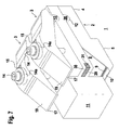
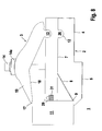
- FIGS. 7 and 8th show an extension of the clamping device (1) of FIGS. 1 to 6
- the tensioning device (1) of FIGS. 7 and 8th has as an additional module on an adapter (25) which is arranged between the lower jaw (2) and the brackets (3).
- the adapter that is in FIG. 9 is shown in a single representation is formed as a solid part having on its underside a cylinder segment (26) that corresponds in terms of its contour to the cylinder segment (13) of the brackets (3).
- a recess (27) is provided which corresponds to the recess (12) of the lower jaw (2).
- the adapter (25) on its upper side Ausmündende threaded holes (28) corresponding to the threaded holes (16) of the lower jaw (2).
- the adapter (25) has a recess (29) which opens out at its front side (30) and closes over the entire width of the adapter (25).
- a magnet (31) is inserted in the recess (29) inserted.
- the magnet (31) terminates flush with the front side (30) and forms with this a flat surface.
- the configuration of the tensioning device (1) of FIG. 1 can in the configuration of FIGS. 7 and 8th be simply converted by the clips (3) are removed from the lower jaw (2) and then the adapter (25) on the lower jaw (2) is fixed by the cylinder segment (26) of the adapter (25) in the recess ( 12) of the lower jaw (2) is introduced. Subsequently, the cylinder segments (13) of the clamps (3) are inserted into the recess (27) of the adapter (25). In principle, this can in turn be done by lateral insertion of the cylinder segments (13) of the brackets (3) in the recess (27) of the adapter.
- FIGS. 7 and 8th are the contours of the cylinder segments (13) of the brackets (3) over the embodiment of FIGS. 1 to 6 modified so that the cylinder segments (13) can be inserted from above into the recess (27) and then fixed in position there by turning into their working positions.
- brackets (3) are then pivotally mounted on the adapter (25), wherein the clamping operations again by pressing the screws (14) takes place, which now engage in the threaded bore (28) of the adapter (25).
- FIG. 8 closes when mounted on the lower jaw (2) adapter (25) whose front side (30) flush with the shoulder 9 of the lower jaw (2).
- the front side (30) forms a stop surface for the workpiece
- the flat front is already correctly applied to the stop (9) when applied to the front side (30).
- the magnet (31) on the front side (30) of the adapter (25) the workpiece is held securely in this desired position, so that then the clamping operation with the brackets (3) can be performed.
Landscapes
- Engineering & Computer Science (AREA)
- Mechanical Engineering (AREA)
- Physics & Mathematics (AREA)
- Thermal Sciences (AREA)
- Jigs For Machine Tools (AREA)
- Electrical Discharge Machining, Electrochemical Machining, And Combined Machining (AREA)
Applications Claiming Priority (1)
| Application Number | Priority Date | Filing Date | Title |
|---|---|---|---|
| DE200910011612 DE102009011612B3 (de) | 2009-03-04 | 2009-03-04 | Spannvorrichtung |
Publications (3)
| Publication Number | Publication Date |
|---|---|
| EP2226145A2 true EP2226145A2 (fr) | 2010-09-08 |
| EP2226145A3 EP2226145A3 (fr) | 2010-11-17 |
| EP2226145B1 EP2226145B1 (fr) | 2016-06-29 |
Family
ID=42320003
Family Applications (1)
| Application Number | Title | Priority Date | Filing Date |
|---|---|---|---|
| EP10001822.5A Not-in-force EP2226145B1 (fr) | 2009-03-04 | 2010-02-23 | Dispositif de serrage |
Country Status (2)
| Country | Link |
|---|---|
| EP (1) | EP2226145B1 (fr) |
| DE (1) | DE102009011612B3 (fr) |
Cited By (8)
| Publication number | Priority date | Publication date | Assignee | Title |
|---|---|---|---|---|
| CN102310239A (zh) * | 2011-05-17 | 2012-01-11 | 泰德兴精密电子(昆山)有限公司 | 慢丝加工装夹治具 |
| CN104096937A (zh) * | 2014-07-07 | 2014-10-15 | 郑州磨料磨具磨削研究所有限公司 | 工件毛坯件快速定位方法及定位夹具 |
| CN104526096A (zh) * | 2014-11-10 | 2015-04-22 | 宁波市博虹机械制造开发有限公司 | 一种牛头式数控电火花机床加工行程专用夹具 |
| CN106112160A (zh) * | 2016-08-31 | 2016-11-16 | 安徽博微长安电子有限公司 | 内导体移位加工定位工装及内导体加工方法 |
| CN108311925A (zh) * | 2017-11-08 | 2018-07-24 | 如皋市大生线路器材有限公司 | 一种车床用工件外轮廓加工夹具 |
| CN111890088A (zh) * | 2020-08-26 | 2020-11-06 | 李万朋 | 一种l型高速架模治具 |
| DE102021112157B3 (de) | 2021-05-10 | 2022-09-01 | F. J. Pfeffer Formenbau Gmbh | Spannvorrichtung |
| CN117399813A (zh) * | 2023-10-31 | 2024-01-16 | 宁波信泰机械有限公司 | 一种汽车复材内板多功能加工设备以及方法 |
Families Citing this family (3)
| Publication number | Priority date | Publication date | Assignee | Title |
|---|---|---|---|---|
| CN106424992B (zh) * | 2016-08-30 | 2018-04-10 | 四川科思精密模具有限公司 | 电极t型夹座 |
| DE102018214220A1 (de) * | 2018-08-22 | 2020-02-27 | Michael Adam | Spannmittel für die Drahterosion und Verwendung eines Spannmittels für die Drahterosion |
| CN121403099B (zh) * | 2025-12-25 | 2026-04-14 | 山西永强电气有限公司 | 一种并沟线夹及其生产用定位钻孔设备及使用方法 |
Citations (3)
| Publication number | Priority date | Publication date | Assignee | Title |
|---|---|---|---|---|
| CH238881A (de) | 1943-01-18 | 1945-08-31 | Wenk Wilhelm | Vorrichtung zum Einspannen von Werkstücken. |
| US5860691A (en) | 1996-03-22 | 1999-01-19 | Lund Industries, Incorporated | Apparatus for covering a vehicle cargo area |
| DE10063988A1 (de) | 1999-12-27 | 2001-07-05 | Colcom S R L | Selbstvestellbare Klemmvorrichtung zum Halten plattenförmiger Elemente im allgemeinen |
Family Cites Families (6)
| Publication number | Priority date | Publication date | Assignee | Title |
|---|---|---|---|---|
| DE945920C (de) * | 1941-01-29 | 1956-07-19 | Elisabeth Heuer Geb Wortmann | Spannlasche zum Befestigen eines Werkstueckes auf einem Maschinentisch |
| US2365079A (en) * | 1943-08-31 | 1944-12-12 | Westinghouse Electric & Mfg Co | Work-holding apparatus |
| DE2936869C2 (de) * | 1979-09-12 | 1987-03-12 | Karl-Heinz Arnold, Hartmetallwerkzeuge-Großhandel, 7302 Ostfildern | Schneidwerkzeug für die spanabhebende Bearbeitung |
| DE19932037C1 (de) * | 1999-07-09 | 2001-01-04 | Wolfgang Rothfuss | Spannelement zum Festspannen von Teilen mit unterschiedlichen Dicken |
| DE20210020U1 (de) * | 2002-02-27 | 2002-10-31 | Rothfuss, Wolfgang, 72270 Baiersbronn | Spannelement zum Spannen von Teilen mit unterschiedlichen Höhen |
| US7011284B2 (en) * | 2002-06-14 | 2006-03-14 | Truck Accessories Group, Inc. | Pivotable clamp |
-
2009
- 2009-03-04 DE DE200910011612 patent/DE102009011612B3/de not_active Expired - Fee Related
-
2010
- 2010-02-23 EP EP10001822.5A patent/EP2226145B1/fr not_active Not-in-force
Patent Citations (3)
| Publication number | Priority date | Publication date | Assignee | Title |
|---|---|---|---|---|
| CH238881A (de) | 1943-01-18 | 1945-08-31 | Wenk Wilhelm | Vorrichtung zum Einspannen von Werkstücken. |
| US5860691A (en) | 1996-03-22 | 1999-01-19 | Lund Industries, Incorporated | Apparatus for covering a vehicle cargo area |
| DE10063988A1 (de) | 1999-12-27 | 2001-07-05 | Colcom S R L | Selbstvestellbare Klemmvorrichtung zum Halten plattenförmiger Elemente im allgemeinen |
Cited By (11)
| Publication number | Priority date | Publication date | Assignee | Title |
|---|---|---|---|---|
| CN102310239A (zh) * | 2011-05-17 | 2012-01-11 | 泰德兴精密电子(昆山)有限公司 | 慢丝加工装夹治具 |
| CN104096937A (zh) * | 2014-07-07 | 2014-10-15 | 郑州磨料磨具磨削研究所有限公司 | 工件毛坯件快速定位方法及定位夹具 |
| CN104526096A (zh) * | 2014-11-10 | 2015-04-22 | 宁波市博虹机械制造开发有限公司 | 一种牛头式数控电火花机床加工行程专用夹具 |
| CN104526096B (zh) * | 2014-11-10 | 2017-01-25 | 宁波市博虹机械制造开发有限公司 | 一种牛头式数控电火花机床加工行程专用夹具 |
| CN106112160A (zh) * | 2016-08-31 | 2016-11-16 | 安徽博微长安电子有限公司 | 内导体移位加工定位工装及内导体加工方法 |
| CN106112160B (zh) * | 2016-08-31 | 2018-02-23 | 安徽博微长安电子有限公司 | 内导体移位加工定位工装及内导体加工方法 |
| CN108311925A (zh) * | 2017-11-08 | 2018-07-24 | 如皋市大生线路器材有限公司 | 一种车床用工件外轮廓加工夹具 |
| CN111890088A (zh) * | 2020-08-26 | 2020-11-06 | 李万朋 | 一种l型高速架模治具 |
| DE102021112157B3 (de) | 2021-05-10 | 2022-09-01 | F. J. Pfeffer Formenbau Gmbh | Spannvorrichtung |
| EP4088864A1 (fr) | 2021-05-10 | 2022-11-16 | F. J. Pfeffer Formenbau GmbH | Dispositif de serrage |
| CN117399813A (zh) * | 2023-10-31 | 2024-01-16 | 宁波信泰机械有限公司 | 一种汽车复材内板多功能加工设备以及方法 |
Also Published As
| Publication number | Publication date |
|---|---|
| EP2226145B1 (fr) | 2016-06-29 |
| DE102009011612B3 (de) | 2010-10-28 |
| EP2226145A3 (fr) | 2010-11-17 |
Similar Documents
| Publication | Publication Date | Title |
|---|---|---|
| EP2226145B1 (fr) | Dispositif de serrage | |
| EP2384857A1 (fr) | Dispositif de serrage d'une pièce usinée | |
| DE19529004A1 (de) | Werkstückhaltevorrichtung | |
| DE10132721C1 (de) | Schneidvorrichtung | |
| EP0254741B1 (fr) | Dispositif de retenue et de manipulation d'un objet plat | |
| WO2008058524A1 (fr) | Outil d'usinage par enlèvement de matière | |
| DE2542804B2 (de) | Abstech- und Einstechwerkzeug | |
| DE3119834C2 (fr) | ||
| EP1815939A1 (fr) | Element de positionement pour unité de fixation avec des plaques de positionement et une console coulissant par un système rainure-ecrou en T ; Unité de fixation avec un tel élément de positionement | |
| EP3215317A1 (fr) | Dispositif de serrage | |
| WO1993023199A1 (fr) | Capot de protection pour machines-outils a travailler le bois | |
| DE29813637U1 (de) | Vektorhaltevorrichtung mit Eignung zum automatischen Zentrieren | |
| DE19700151A1 (de) | Verbesserung bei Vorrichtungen zum Entfernen von Windschutzscheiben | |
| EP4088864B1 (fr) | Dispositif de serrage | |
| EP0544871B1 (fr) | Machine pour l'usinage multiphase de lames de scies circulaires | |
| DE19912979C1 (de) | Werkzeugkopf für eine Drehmaschine | |
| DE20107746U1 (de) | Tischplatte, insbesondere zum Positionieren und Fixieren eines Werkstücks | |
| DE10391648B4 (de) | Stützvorrichtung für Spanngut in einer Spannvorrichtung | |
| CH673245A5 (fr) | ||
| EP2686120B1 (fr) | Dispositif de positionnement d'outil sur une presse à cintrer | |
| DE69502467T2 (de) | Reibschweisswerkzeug | |
| DE2034993B2 (de) | Schneidwerkzeug für spanabhebende Bearbeitung | |
| DE19500946C1 (de) | Winkelverstellbarer Werkstücksitz | |
| DE3133227C2 (de) | Spannvorrichtung für Blechteile, insbesondere Bestecke | |
| DE102017112664B4 (de) | Spannsystem mit wenigstens drei Spannelementen |
Legal Events
| Date | Code | Title | Description |
|---|---|---|---|
| PUAI | Public reference made under article 153(3) epc to a published international application that has entered the european phase |
Free format text: ORIGINAL CODE: 0009012 |
|
| AK | Designated contracting states |
Kind code of ref document: A2 Designated state(s): AT BE BG CH CY CZ DE DK EE ES FI FR GB GR HR HU IE IS IT LI LT LU LV MC MK MT NL NO PL PT RO SE SI SK SM TR |
|
| AX | Request for extension of the european patent |
Extension state: AL BA RS |
|
| PUAL | Search report despatched |
Free format text: ORIGINAL CODE: 0009013 |
|
| AK | Designated contracting states |
Kind code of ref document: A3 Designated state(s): AT BE BG CH CY CZ DE DK EE ES FI FR GB GR HR HU IE IS IT LI LT LU LV MC MK MT NL NO PL PT RO SE SI SK SM TR |
|
| AX | Request for extension of the european patent |
Extension state: AL BA RS |
|
| 17P | Request for examination filed |
Effective date: 20101204 |
|
| 17Q | First examination report despatched |
Effective date: 20130122 |
|
| REG | Reference to a national code |
Ref country code: DE Ref legal event code: R079 Ref document number: 502010011892 Country of ref document: DE Free format text: PREVIOUS MAIN CLASS: B23H0011000000 Ipc: B25B0005100000 |
|
| RIC1 | Information provided on ipc code assigned before grant |
Ipc: B23H 11/00 20060101ALI20160122BHEP Ipc: B23H 9/10 20060101ALI20160122BHEP Ipc: B25B 5/10 20060101AFI20160122BHEP |
|
| GRAP | Despatch of communication of intention to grant a patent |
Free format text: ORIGINAL CODE: EPIDOSNIGR1 |
|
| INTG | Intention to grant announced |
Effective date: 20160323 |
|
| GRAS | Grant fee paid |
Free format text: ORIGINAL CODE: EPIDOSNIGR3 |
|
| GRAA | (expected) grant |
Free format text: ORIGINAL CODE: 0009210 |
|
| AK | Designated contracting states |
Kind code of ref document: B1 Designated state(s): AT BE BG CH CY CZ DE DK EE ES FI FR GB GR HR HU IE IS IT LI LT LU LV MC MK MT NL NO PL PT RO SE SI SK SM TR |
|
| REG | Reference to a national code |
Ref country code: GB Ref legal event code: FG4D Free format text: NOT ENGLISH |
|
| REG | Reference to a national code |
Ref country code: CH Ref legal event code: EP |
|
| REG | Reference to a national code |
Ref country code: AT Ref legal event code: REF Ref document number: 808702 Country of ref document: AT Kind code of ref document: T Effective date: 20160715 |
|
| REG | Reference to a national code |
Ref country code: IE Ref legal event code: FG4D Free format text: LANGUAGE OF EP DOCUMENT: GERMAN |
|
| REG | Reference to a national code |
Ref country code: DE Ref legal event code: R096 Ref document number: 502010011892 Country of ref document: DE |
|
| REG | Reference to a national code |
Ref country code: LT Ref legal event code: MG4D |
|
| PG25 | Lapsed in a contracting state [announced via postgrant information from national office to epo] |
Ref country code: LT Free format text: LAPSE BECAUSE OF FAILURE TO SUBMIT A TRANSLATION OF THE DESCRIPTION OR TO PAY THE FEE WITHIN THE PRESCRIBED TIME-LIMIT Effective date: 20160629 Ref country code: FI Free format text: LAPSE BECAUSE OF FAILURE TO SUBMIT A TRANSLATION OF THE DESCRIPTION OR TO PAY THE FEE WITHIN THE PRESCRIBED TIME-LIMIT Effective date: 20160629 Ref country code: NO Free format text: LAPSE BECAUSE OF FAILURE TO SUBMIT A TRANSLATION OF THE DESCRIPTION OR TO PAY THE FEE WITHIN THE PRESCRIBED TIME-LIMIT Effective date: 20160929 |
|
| REG | Reference to a national code |
Ref country code: NL Ref legal event code: MP Effective date: 20160629 |
|
| PG25 | Lapsed in a contracting state [announced via postgrant information from national office to epo] |
Ref country code: SE Free format text: LAPSE BECAUSE OF FAILURE TO SUBMIT A TRANSLATION OF THE DESCRIPTION OR TO PAY THE FEE WITHIN THE PRESCRIBED TIME-LIMIT Effective date: 20160629 Ref country code: HR Free format text: LAPSE BECAUSE OF FAILURE TO SUBMIT A TRANSLATION OF THE DESCRIPTION OR TO PAY THE FEE WITHIN THE PRESCRIBED TIME-LIMIT Effective date: 20160629 Ref country code: GR Free format text: LAPSE BECAUSE OF FAILURE TO SUBMIT A TRANSLATION OF THE DESCRIPTION OR TO PAY THE FEE WITHIN THE PRESCRIBED TIME-LIMIT Effective date: 20160930 Ref country code: NL Free format text: LAPSE BECAUSE OF FAILURE TO SUBMIT A TRANSLATION OF THE DESCRIPTION OR TO PAY THE FEE WITHIN THE PRESCRIBED TIME-LIMIT Effective date: 20160629 Ref country code: LV Free format text: LAPSE BECAUSE OF FAILURE TO SUBMIT A TRANSLATION OF THE DESCRIPTION OR TO PAY THE FEE WITHIN THE PRESCRIBED TIME-LIMIT Effective date: 20160629 |
|
| PG25 | Lapsed in a contracting state [announced via postgrant information from national office to epo] |
Ref country code: CZ Free format text: LAPSE BECAUSE OF FAILURE TO SUBMIT A TRANSLATION OF THE DESCRIPTION OR TO PAY THE FEE WITHIN THE PRESCRIBED TIME-LIMIT Effective date: 20160629 Ref country code: IS Free format text: LAPSE BECAUSE OF FAILURE TO SUBMIT A TRANSLATION OF THE DESCRIPTION OR TO PAY THE FEE WITHIN THE PRESCRIBED TIME-LIMIT Effective date: 20161029 Ref country code: EE Free format text: LAPSE BECAUSE OF FAILURE TO SUBMIT A TRANSLATION OF THE DESCRIPTION OR TO PAY THE FEE WITHIN THE PRESCRIBED TIME-LIMIT Effective date: 20160629 Ref country code: RO Free format text: LAPSE BECAUSE OF FAILURE TO SUBMIT A TRANSLATION OF THE DESCRIPTION OR TO PAY THE FEE WITHIN THE PRESCRIBED TIME-LIMIT Effective date: 20160629 Ref country code: IT Free format text: LAPSE BECAUSE OF FAILURE TO SUBMIT A TRANSLATION OF THE DESCRIPTION OR TO PAY THE FEE WITHIN THE PRESCRIBED TIME-LIMIT Effective date: 20160629 Ref country code: SK Free format text: LAPSE BECAUSE OF FAILURE TO SUBMIT A TRANSLATION OF THE DESCRIPTION OR TO PAY THE FEE WITHIN THE PRESCRIBED TIME-LIMIT Effective date: 20160629 |
|
| REG | Reference to a national code |
Ref country code: FR Ref legal event code: PLFP Year of fee payment: 8 |
|
| PG25 | Lapsed in a contracting state [announced via postgrant information from national office to epo] |
Ref country code: PT Free format text: LAPSE BECAUSE OF FAILURE TO SUBMIT A TRANSLATION OF THE DESCRIPTION OR TO PAY THE FEE WITHIN THE PRESCRIBED TIME-LIMIT Effective date: 20161031 Ref country code: PL Free format text: LAPSE BECAUSE OF FAILURE TO SUBMIT A TRANSLATION OF THE DESCRIPTION OR TO PAY THE FEE WITHIN THE PRESCRIBED TIME-LIMIT Effective date: 20160629 Ref country code: ES Free format text: LAPSE BECAUSE OF FAILURE TO SUBMIT A TRANSLATION OF THE DESCRIPTION OR TO PAY THE FEE WITHIN THE PRESCRIBED TIME-LIMIT Effective date: 20160629 Ref country code: SM Free format text: LAPSE BECAUSE OF FAILURE TO SUBMIT A TRANSLATION OF THE DESCRIPTION OR TO PAY THE FEE WITHIN THE PRESCRIBED TIME-LIMIT Effective date: 20160629 |
|
| REG | Reference to a national code |
Ref country code: DE Ref legal event code: R097 Ref document number: 502010011892 Country of ref document: DE |
|
| PLBE | No opposition filed within time limit |
Free format text: ORIGINAL CODE: 0009261 |
|
| STAA | Information on the status of an ep patent application or granted ep patent |
Free format text: STATUS: NO OPPOSITION FILED WITHIN TIME LIMIT |
|
| PG25 | Lapsed in a contracting state [announced via postgrant information from national office to epo] |
Ref country code: BE Free format text: LAPSE BECAUSE OF NON-PAYMENT OF DUE FEES Effective date: 20170228 Ref country code: DK Free format text: LAPSE BECAUSE OF FAILURE TO SUBMIT A TRANSLATION OF THE DESCRIPTION OR TO PAY THE FEE WITHIN THE PRESCRIBED TIME-LIMIT Effective date: 20160629 |
|
| 26N | No opposition filed |
Effective date: 20170330 |
|
| PG25 | Lapsed in a contracting state [announced via postgrant information from national office to epo] |
Ref country code: BG Free format text: LAPSE BECAUSE OF FAILURE TO SUBMIT A TRANSLATION OF THE DESCRIPTION OR TO PAY THE FEE WITHIN THE PRESCRIBED TIME-LIMIT Effective date: 20160929 Ref country code: SI Free format text: LAPSE BECAUSE OF FAILURE TO SUBMIT A TRANSLATION OF THE DESCRIPTION OR TO PAY THE FEE WITHIN THE PRESCRIBED TIME-LIMIT Effective date: 20160629 |
|
| REG | Reference to a national code |
Ref country code: DE Ref legal event code: R119 Ref document number: 502010011892 Country of ref document: DE |
|
| PG25 | Lapsed in a contracting state [announced via postgrant information from national office to epo] |
Ref country code: MC Free format text: LAPSE BECAUSE OF FAILURE TO SUBMIT A TRANSLATION OF THE DESCRIPTION OR TO PAY THE FEE WITHIN THE PRESCRIBED TIME-LIMIT Effective date: 20160629 |
|
| REG | Reference to a national code |
Ref country code: CH Ref legal event code: PL |
|
| GBPC | Gb: european patent ceased through non-payment of renewal fee |
Effective date: 20170223 |
|
| PG25 | Lapsed in a contracting state [announced via postgrant information from national office to epo] |
Ref country code: LI Free format text: LAPSE BECAUSE OF NON-PAYMENT OF DUE FEES Effective date: 20170228 Ref country code: CH Free format text: LAPSE BECAUSE OF NON-PAYMENT OF DUE FEES Effective date: 20170228 |
|
| REG | Reference to a national code |
Ref country code: IE Ref legal event code: MM4A |
|
| PG25 | Lapsed in a contracting state [announced via postgrant information from national office to epo] |
Ref country code: LU Free format text: LAPSE BECAUSE OF NON-PAYMENT OF DUE FEES Effective date: 20170223 |
|
| PG25 | Lapsed in a contracting state [announced via postgrant information from national office to epo] |
Ref country code: DE Free format text: LAPSE BECAUSE OF NON-PAYMENT OF DUE FEES Effective date: 20170901 |
|
| REG | Reference to a national code |
Ref country code: BE Ref legal event code: MM Effective date: 20170228 |
|
| REG | Reference to a national code |
Ref country code: FR Ref legal event code: PLFP Year of fee payment: 9 |
|
| PG25 | Lapsed in a contracting state [announced via postgrant information from national office to epo] |
Ref country code: IE Free format text: LAPSE BECAUSE OF NON-PAYMENT OF DUE FEES Effective date: 20170223 Ref country code: GB Free format text: LAPSE BECAUSE OF NON-PAYMENT OF DUE FEES Effective date: 20170223 |
|
| REG | Reference to a national code |
Ref country code: AT Ref legal event code: MM01 Ref document number: 808702 Country of ref document: AT Kind code of ref document: T Effective date: 20170223 |
|
| PG25 | Lapsed in a contracting state [announced via postgrant information from national office to epo] |
Ref country code: AT Free format text: LAPSE BECAUSE OF NON-PAYMENT OF DUE FEES Effective date: 20170223 |
|
| PG25 | Lapsed in a contracting state [announced via postgrant information from national office to epo] |
Ref country code: MT Free format text: LAPSE BECAUSE OF FAILURE TO SUBMIT A TRANSLATION OF THE DESCRIPTION OR TO PAY THE FEE WITHIN THE PRESCRIBED TIME-LIMIT Effective date: 20160629 |
|
| PG25 | Lapsed in a contracting state [announced via postgrant information from national office to epo] |
Ref country code: HU Free format text: LAPSE BECAUSE OF FAILURE TO SUBMIT A TRANSLATION OF THE DESCRIPTION OR TO PAY THE FEE WITHIN THE PRESCRIBED TIME-LIMIT; INVALID AB INITIO Effective date: 20100223 |
|
| PG25 | Lapsed in a contracting state [announced via postgrant information from national office to epo] |
Ref country code: CY Free format text: LAPSE BECAUSE OF NON-PAYMENT OF DUE FEES Effective date: 20160629 |
|
| PG25 | Lapsed in a contracting state [announced via postgrant information from national office to epo] |
Ref country code: MK Free format text: LAPSE BECAUSE OF FAILURE TO SUBMIT A TRANSLATION OF THE DESCRIPTION OR TO PAY THE FEE WITHIN THE PRESCRIBED TIME-LIMIT Effective date: 20160629 |
|
| PG25 | Lapsed in a contracting state [announced via postgrant information from national office to epo] |
Ref country code: TR Free format text: LAPSE BECAUSE OF FAILURE TO SUBMIT A TRANSLATION OF THE DESCRIPTION OR TO PAY THE FEE WITHIN THE PRESCRIBED TIME-LIMIT Effective date: 20160629 |
|
| PGFP | Annual fee paid to national office [announced via postgrant information from national office to epo] |
Ref country code: FR Payment date: 20220216 Year of fee payment: 13 |
|
| PG25 | Lapsed in a contracting state [announced via postgrant information from national office to epo] |
Ref country code: FR Free format text: LAPSE BECAUSE OF NON-PAYMENT OF DUE FEES Effective date: 20230228 |