EP2226156A2 - Pinces de verrouillage avec ajustement à une main - Google Patents
Pinces de verrouillage avec ajustement à une main Download PDFInfo
- Publication number
- EP2226156A2 EP2226156A2 EP10002061A EP10002061A EP2226156A2 EP 2226156 A2 EP2226156 A2 EP 2226156A2 EP 10002061 A EP10002061 A EP 10002061A EP 10002061 A EP10002061 A EP 10002061A EP 2226156 A2 EP2226156 A2 EP 2226156A2
- Authority
- EP
- European Patent Office
- Prior art keywords
- wheel
- jaw
- handle
- locking
- pliers
- Prior art date
- Legal status (The legal status is an assumption and is not a legal conclusion. Google has not performed a legal analysis and makes no representation as to the accuracy of the status listed.)
- Withdrawn
Links
Images


Classifications
-
- B—PERFORMING OPERATIONS; TRANSPORTING
- B25—HAND TOOLS; PORTABLE POWER-DRIVEN TOOLS; MANIPULATORS
- B25B—TOOLS OR BENCH DEVICES NOT OTHERWISE PROVIDED FOR, FOR FASTENING, CONNECTING, DISENGAGING, OR HOLDING
- B25B7/00—Pliers; Other hand-held gripping tools with jaws on pivoted limbs; Details applicable generally to pivoted-limb hand tools
- B25B7/12—Pliers; Other hand-held gripping tools with jaws on pivoted limbs; Details applicable generally to pivoted-limb hand tools involving special transmission means between the handles and the jaws, e.g. toggle levers, gears
- B25B7/123—Pliers; Other hand-held gripping tools with jaws on pivoted limbs; Details applicable generally to pivoted-limb hand tools involving special transmission means between the handles and the jaws, e.g. toggle levers, gears with self-locking toggle levers
Definitions
- This invention relates generally to locking pliers and, more particularly, to a locking pliers that can be adjusted with one hand.
- Pliers-type hand tools with toggle-locking mechanisms are generally known as locking pliers. These pliers usually comprise a fixed handle having a fixed jaw on one end thereof. A movable handle pivots a movable jaw relative to the fixed handle to open and close the jaws. To grip a workpiece the handles are tightly compressed such that the linkage of the toggle-locking mechanism locks the pliers onto the workpiece. Adjustments in the jaw opening and the force applied by the jaws to the workpiece are generally made by turning an adjusting screw mounted in the fixed handle that engages the toggle locking mechanism. Typically the pliers are held in one hand and the adjusting screw is rotated using the other hand.
- the adjusting screw is translated relative to the fixed handle to modify the physical dimensions of the toggle mechanism to vary the effective length of the linkage of the toggle-locking mechanism. This adjustment varies the distance between the ends of the toggle linkage to vary the force applied by the jaws to the workpiece when the tool is locked. The pliers will remain firmly locked in place without the continuous application of force by the user.
- a locking pliers comprises a fixed assembly comprising a first handle supporting a first jaw.
- a second jaw is movable relative to the first jaw between an open position and a closed, locked position.
- a second handle moves relative to the first handle to move the second jaw between open and closed positions.
- a toggle-link locking mechanism locks the second jaw in the closed, locked position.
- An adjusting screw is provided for adjusting the geometry of the locking mechanism to thereby adjust the jaw spacing and the force exerted by the jaws is provided. This adjustment varies the distance between the ends of the toggle linkage to vary the force applied by the jaws to the workpiece when the tool is locked.
- the adjusting screw includes a wheel that can be rotated by running the wheel along an object.
- the adjusting screw includes a sleeve that extends partially over the fixed assembly such that it can be manipulated by the same hand that holds the locking pliers.
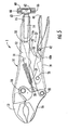
- Pliers 1 include a fixed assembly 10 having a fixed handle 12 at one end and a fixed jaw 13 at the other end.
- a movable handle 19 is pivotably connected at one end to a movable jaw 16 by pivot pin 20.
- a pivot pin 18 connects the movable jaw 16 to the fixed assembly 10.
- the fixed assembly 10 receives the pivot pin 18.
- a toggle locking mechanism 27 locks the movable jaw 16 relative to the fixed jaw 13.
- a link 22 is pivotably connected to the movable handle 19 by a pivot pin 26.
- the opposite end 32 of link 22 is in sliding and pivoting contact with the end 14a of adjustment screw 14.
- a projection 33 extends transversely to the length direction of the link 22 and acts as a stop when the jaws are in the closed position. The projection 33 may contact with the handle 19 directly.
- a release lever 40 may be provided where one end of the lever 40a is disposed between the lever and the handle 19.
- the lever 40 is pivoted to the movable handle 19 at pin 42 such that a user can depress the distal end of lever 40 to lift end 40a and unlock the linkage 27.
- a biasing spring 29 extends between an opening 30 on the movable jaw 16 to a tab 31 protruding from fixed handle 12. The spring 29 applies a bias which tends to move the jaws 13 and 16 away from one another.
- the pivot points, 18, 20, 26 and the point of contact between the end 32 of link 22 with the end of the adjusting screw 14 are arranged as a polygon.
- the pivots 20, 26 and the point of contact between link 22 and screw 14 are substantially in a straight line with the pin 26 in an over-center position where it is positioned slightly inside (toward fixed assembly 10) of the line between pivot 20 and the point of contact between link 22 and the screw 14.
- the jaws 13 and 16 cannot be pried apart from the locked position by use of force which pulls or pushes on the jaws 13 and 16 because separation of the jaws is prevented by the over-center condition of the pin 26.
- the jaws 13 and 16 may be separated by applying a force to the movable handle 19 in a direction which moves the movable handle 19 away from the fixed handle 12.
- a configuration of the pivots which places the mechanism in a locked position when the jaws are closed or grasping a workpiece can be considered an over-center mechanism when force applied directly to the jaws is not effective in separating the jaws.
- the jaws can only be opened by forces acting on the links of the mechanism.
- Other locking mechanisms are known and may also be used to lock the handles relative to one another.
- the locking mechanism may include a compound linkage for effecting the locking function.
- the end of the fixed handle 12, remote from the jaw 13, is completed with a threaded circular aperture 15 through which threaded adjustment screw 14 is threadably engaged.
- the end 32 of the link 22 is slidably and pivotably engaged with the end of the adjusting screw 14.
- turning the adjusting screw 14 changes the distance between the end 32 of the link 22 and the pivot point 18 of the movable jaw 16 to change the geometry of the linkage, whereby the jaws may be adjusted to grip objects of different dimensions with varying force.
- the adjusting screw 14 includes a wheel 50 is connected to the distal end of the adjusting screw that is used to rotate the screw to make the adjustment.
- the wheel 50 may either be a separate component that is fixed to the adjusting screw or the wheel 50 may be formed as one piece with the adjusting screw.
- the wheel 50 is sized such that it can be rotated by the friction of running the wheel along an object.
- the adjusting screw includes a large diameter wheel that allows the user to run the wheel over, for example, the user's leg to adjust the pliers. This allows the user to adjust the pliers using only one hand leaving the user's other hand free.
- the ability of the pliers to be adjusted by running the wheel over a surface is based on the geometry of the wheel as it relates to the mechanics of the pliers.
- the wheel may be provided with an increased thickness t such that sufficient surface area is provided to engage the surface with which the wheel is engaged.
- the wheel may be provided with a knurled peripheral outer surface 50a to increase the frictional engagement of the wheel with the surface.
- the radius of the wheel is based on the mechanics of the locking pliers. The radius depends on the size of the locking pliers where a larger locking pliers requires a larger diameter wheel. Reference is made to Figs. 2 through 4 to explain the appropriate wheel dimension. In these figures:
- the desired minimum size of the wheel is a one inch diameter. If the wheel has a diameter much greater than 1.5 inches it has been found that, while the wheel can adjust the locking pliers, the profile of the wheel becomes somewhat unwieldy and may interfere with the use of the pliers. A wheel having a diameter of 1.5 inches has been found to work well for most sized locking pliers. Thus, a diameter of between approximately 7/8 inch and approximately 1.5 inches is most preferred for most locking pliers.
- the wheel 50 has a width t suitable to allow the wheel 50 to be pressed against a surface and rotate the screw 14. While the width t of the wheel 50 theoretically does not affect the ability of the wheel to rotate the adjustment screw 14, the wheel 50 should have a width sufficient to provide sufficient traction between the wheel 50 and the surface against which the wheel is pressed. Moreover, the width of wheel 50 should be sufficient to be comfortable when pressed against the user's body.
- the wheel 50 can be formed as an integral part of the screw where the wheel and screw form part of the pliers as manufactured and sold.
- the wheel and adjusting screw may be one piece.
- the screw 14 with the large wheel 50 of the invention can be sold separately as a replacement part for existing pliers.
- the existing screw can be removed from the handle 12 by unscrewing the screw from the threaded aperture 15.
- the replacement screw 14 with the large wheel 50 of the invention can then be screwed into the threaded aperture 15.
- the wheel 60 can be formed as a separate component that is attached to the existing screw of a locking pliers.
- the wheel 60 includes a socket 62 that receives the head 63 of the existing screw 14.
- a set screw or a plurality of set screws 66 can be used to fix the wheel to the head of the screw.
- Other attachment mechanisms may also be used such as adhesive, a press fit, friction fit or the like.
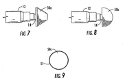
- the wheel may also be formed as a truncated cone as shown in Fig. 7 rather than as a cylinder as shown in Figs. 1 through 6 .
- the wheel 50a By making the wheel 50a a truncated cone the pliers can be held at an angle relative to the surface against which the wheel is pressed and rotated. Such an orientation may be more comfortable for the user in some uses.
- the wheel may also have a spherical or semi-spherical shape as shown at wheel 50b in Fig. 8 .
- the rounded portion of the wheel may be a round sphere or an oval sphere.
- the peripheral outer surface of the wheel 50c may also be formed with gear teeth 51 to increase the traction of the wheel with the surface.
- the wheel may have other shapes that allow the wheel to rotate when pressed against and rolled over a surface.
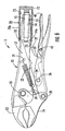
- FIG. 6 Another embodiment of the invention is shown in Fig. 6 .
- Sleeve 70 comprises a member having a first end 72 that is connected to the exposed end of the adjustment screw 14.
- the sleeve may be a separate component that is fixed to the adjusting screw or the sleeve and adjusting screw may be made in one piece.
- the sleeve has a second end 75 that defines an interior cavity 73 for receiving handle 12.
- the sleeve 70 extends over the fixed handle 12 such that the handle extends into the cavity 73.
- the sleeve 70 extends for a portion of the handle 12 such that it can be manipulated by the same hand that grips the pliers.
- the sleeve 70 may be provided with a cylindrical outer surface 70a.
Landscapes
- Engineering & Computer Science (AREA)
- Mechanical Engineering (AREA)
- Gripping Jigs, Holding Jigs, And Positioning Jigs (AREA)
Applications Claiming Priority (1)
| Application Number | Priority Date | Filing Date | Title |
|---|---|---|---|
| US12/396,083 US20100218648A1 (en) | 2009-03-02 | 2009-03-02 | Locking pliers with one-hand adjustment |
Publications (1)
| Publication Number | Publication Date |
|---|---|
| EP2226156A2 true EP2226156A2 (fr) | 2010-09-08 |
Family
ID=42340328
Family Applications (1)
| Application Number | Title | Priority Date | Filing Date |
|---|---|---|---|
| EP10002061A Withdrawn EP2226156A2 (fr) | 2009-03-02 | 2010-03-01 | Pinces de verrouillage avec ajustement à une main |
Country Status (3)
| Country | Link |
|---|---|
| US (1) | US20100218648A1 (fr) |
| EP (1) | EP2226156A2 (fr) |
| CN (1) | CN101913126A (fr) |
Cited By (1)
| Publication number | Priority date | Publication date | Assignee | Title |
|---|---|---|---|---|
| TWI794467B (zh) * | 2018-04-11 | 2023-03-01 | 德商韋扎格有限責任兩合公司 | 壓接工具 |
Families Citing this family (15)
| Publication number | Priority date | Publication date | Assignee | Title |
|---|---|---|---|---|
| US10295080B2 (en) * | 2012-12-11 | 2019-05-21 | Schneider Electric Buildings, Llc | Fast attachment open end direct mount damper and valve actuator |
| CN103481217B (zh) * | 2013-09-23 | 2015-07-08 | 威海市威力高档工具有限公司 | 一种可自动调节的大力钳 |
| USD771456S1 (en) | 2014-08-01 | 2016-11-15 | Milwaukee Electric Tool Corporation | Pliers with control key |
| US20160039072A1 (en) * | 2014-08-07 | 2016-02-11 | Ming Chieh Wu | Gripping Tool with Adjustor Allowing Quick Adjustments of Clamping Pressure Modes |
| US20160207175A1 (en) | 2015-01-15 | 2016-07-21 | Milwaukee Electric Tool Corporation | Locking pliers with improved adjustment member |
| USD782891S1 (en) | 2015-04-02 | 2017-04-04 | Milwaukee Electric Tool Corporation | Locking pliers |
| US11541514B2 (en) | 2016-03-23 | 2023-01-03 | Milwaukee Electric Tool Corporation | Locking pliers |
| CN114102457B (zh) * | 2016-03-23 | 2024-10-18 | 米沃奇电动工具公司 | 手持工具 |
| CN115042103B (zh) | 2017-09-11 | 2024-07-09 | 米沃奇电动工具公司 | 锁定钳、钳子和用于夹持工件的工具 |
| EP3614507B1 (fr) * | 2018-08-23 | 2021-09-01 | WEZAG GmbH & Co. KG | Pinces à presser ou à sertir |
| USD910395S1 (en) | 2019-03-11 | 2021-02-16 | Milwaukee Electric Tool Corporation | Pliers |
| CN111975664A (zh) * | 2019-05-21 | 2020-11-24 | 吴明杰 | 五连杆夹钳 |
| TWI730669B (zh) * | 2020-03-13 | 2021-06-11 | 新祐工業有限公司 | 多功能鉗具 |
| TWI730670B (zh) * | 2020-03-13 | 2021-06-11 | 新祐工業有限公司 | 省力鉗具 |
| WO2022266307A1 (fr) * | 2021-06-16 | 2022-12-22 | Apex Brands, Inc. | Pince de serrage réglable |
Family Cites Families (9)
| Publication number | Priority date | Publication date | Assignee | Title |
|---|---|---|---|---|
| US2313270A (en) * | 1940-10-23 | 1943-03-09 | Floyd B Sapp | Wrench |
| US3859874A (en) * | 1973-03-15 | 1975-01-14 | Stanley V Joeckel | Plier type tool |
| CN2034503U (zh) * | 1987-11-27 | 1989-03-22 | 陈仰帆 | 多用平口钳 |
| US6164107A (en) * | 1996-12-12 | 2000-12-26 | Korba, Jr.; William | Radius crimping tool |
| US6276651B1 (en) * | 2000-01-14 | 2001-08-21 | George D. Dolan | Mounting device for flagpoles |
| CN2410082Y (zh) * | 2000-03-17 | 2000-12-13 | 东南大学 | 自锁式增力钳 |
| US6450070B1 (en) * | 2001-10-05 | 2002-09-17 | John Andrew Winkler | Locking plier tool |
| CN2728716Y (zh) * | 2004-07-30 | 2005-09-28 | 上海朝华工具有限公司 | 大力钳 |
| CN2846025Y (zh) * | 2005-09-12 | 2006-12-13 | 吴丽珠 | 省力钳子 |
-
2009
- 2009-03-02 US US12/396,083 patent/US20100218648A1/en not_active Abandoned
-
2010
- 2010-03-01 EP EP10002061A patent/EP2226156A2/fr not_active Withdrawn
- 2010-03-02 CN CN201010124031XA patent/CN101913126A/zh active Pending
Non-Patent Citations (1)
| Title |
|---|
| None |
Cited By (1)
| Publication number | Priority date | Publication date | Assignee | Title |
|---|---|---|---|---|
| TWI794467B (zh) * | 2018-04-11 | 2023-03-01 | 德商韋扎格有限責任兩合公司 | 壓接工具 |
Also Published As
| Publication number | Publication date |
|---|---|
| US20100218648A1 (en) | 2010-09-02 |
| CN101913126A (zh) | 2010-12-15 |
Similar Documents
| Publication | Publication Date | Title |
|---|---|---|
| US20100218648A1 (en) | Locking pliers with one-hand adjustment | |
| US7861622B2 (en) | Locking pliers | |
| US8056451B2 (en) | Locking pliers | |
| US7472632B2 (en) | Locking pliers | |
| US5707371A (en) | Repositioning tool | |
| US8776646B2 (en) | Locking pliers | |
| US6708588B2 (en) | Self adjusting mechanism for locking plier, wrench, or other tool | |
| US9492911B2 (en) | Locking pliers with improved adjustment member | |
| US5377567A (en) | Bicycle tool | |
| WO2019051491A1 (fr) | Pinces de verrouillage à section de mâchoire mobile augmentant le couple | |
| US8607671B2 (en) | Wrench with trigger | |
| US8028560B2 (en) | Handheld brake | |
| SE457068B (sv) | Laasbart handverktyg med laangt bett | |
| EP2149429A2 (fr) | Pinces de verrouillage | |
| US7201084B2 (en) | Adjustable ratchet wrench | |
| US20070209484A1 (en) | Locking pliers | |
| US7347125B1 (en) | Automatic adjustable head wrench | |
| US6854365B1 (en) | Wrench | |
| US4438668A (en) | Wrench | |
| US4712455A (en) | Sliding jaw wrench | |
| US818419A (en) | Automatic adjustable-grip pipe-wrench. | |
| AU771591B2 (en) | Wrench |
Legal Events
| Date | Code | Title | Description |
|---|---|---|---|
| PUAI | Public reference made under article 153(3) epc to a published international application that has entered the european phase |
Free format text: ORIGINAL CODE: 0009012 |
|
| AK | Designated contracting states |
Kind code of ref document: A2 Designated state(s): AT BE BG CH CY CZ DE DK EE ES FI FR GB GR HR HU IE IS IT LI LT LU LV MC MK MT NL NO PL PT RO SE SI SK SM TR |
|
| AX | Request for extension of the european patent |
Extension state: AL BA ME RS |
|
| STAA | Information on the status of an ep patent application or granted ep patent |
Free format text: STATUS: THE APPLICATION IS DEEMED TO BE WITHDRAWN |
|
| 18D | Application deemed to be withdrawn |
Effective date: 20121002 |